Arduino -> FLProg -> RS-485 -> Modbus
FLProg version 1.9.1 has been released. I thought that the innovations in the program deserve coverage on Habré. I will also tell you a little theory about the Modbus protocol and the features of its implementation onboard the Arduino.
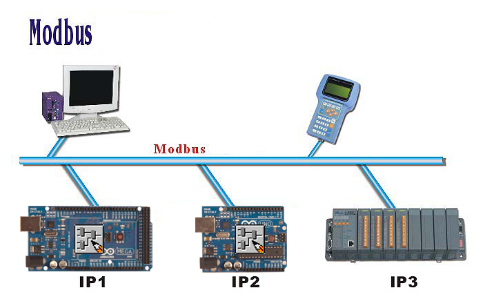
Modbus is a client-server protocol.
Widely used in industry.
Modbus can be used to transmit data via serial communications RS-485, RS-422, RS-232, as well as TCP / IP networks.
While in the program FLProg data transfer is realized only via RS-485.
The RS-485 interface is based on the principle of differential (balanced) data transfer. Its essence lies in the transmission of a single signal over two wires. And one wire (conditionally A) is the original signal, and the other (conditionally B) - its inverse copy. In other words, if on one wire "1", then on the other "0" and vice versa. Thus, between two wires of a twisted pair there is always a potential difference: with “1” it is positive, with “0” it is negative.

It is this potential difference and the signal is transmitted. This transmission method provides high immunity to common mode interference. Common mode is called interference, acting on both wires of the line in the same way. For example, an electromagnetic wave, passing through a section of the communication line, induces a potential in both wires. If a signal is transmitted by a potential in one wire with respect to a common one, as in RS-232, then the tip on this wire may distort the signal of a relatively good absorbing tip of the common ("ground"). In addition, on the resistance of the long common wire will fall the potential difference of the earth - an additional source of distortion. And with differential transmission, no distortion occurs. In fact, if two wires run close to each other, and even intertwined, then the guidance on both wires is the same. The potential in both equally loaded wires varies equally, while the informative potential difference remains unchanged.
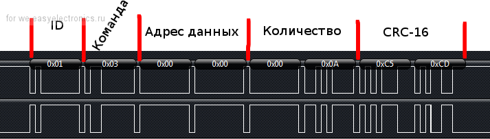
This is what a typical package looks like, from the Master to the Slave.
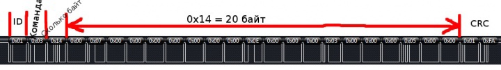
This is what the Slave’s answer to the Lead
ID - Slave address. It can have values from 1 to 247. Address 0 is used for broadcast transmission, each device recognizes it, addresses in the range 248 ... 255 are reserved.
FLProg for the master (Master) supports 32 slave (Slave) devices due to the used UART -> RS-485 converters.
Command (function code):
In this example, one, for reading 0x03.
But in reality there are many more.
All function codes are divided into:
- Public codes described in the MODBUS-IDA standard. Their list includes codes already assigned and used, as well as codes for future use;
List
0x02) - reading values from several discrete inputs (Read Discrete Inputs).
(0x03) - read values from several storage registers (Read Holding Registers).
(0x04) - reading values from several input registers (Read Input Registers).
(0x05) - write the value of one flag (Force Single Coil).
(0x06) - write the value to one storage register (Preset Single Register).
(0x07) - Read Status Signals (Read Exception Status)
(0x0F) - write values to several flag registers (Force Multiple Coils)
(0x10) - write values to several storage registers (Preset Multiple Registers)
(0x16) - write to one storage register using the “AND” mask and the “OR” mask.
(0x18) - Read data from the queue (Read FIFO Queue)
(0x14) - Read from file (Read File Record)
(0x15) - Write File (Write File Record)
(0x08) - Diagnostics (Diagnostic)
(0x0B) - Read Event Counter (Get Com Event Counter)
(0x0C) - Read Event Log (Get Com Event Log)
(0x11) - Reading Device Information (Report Slave ID)
(0x2B) - Encapsulated Interface Transport
- User-Defined Function Codes (65-72, 100-110) - codes that can be used by companies for their own functions, and are not described in the specification;
- Reserved Function Codes (9, 10, 13, 14, 41, 42, 43, 90, 91, 125, 126 and 127) - codes that are not available for general use are reserved.
Error processing
The master sends a request to the Slave, in which in the field “function code” indicates to him the necessary action.
The data bytes contain the information necessary to perform this function.
Slave, in case of successful execution of this function, repeats the function code in the response.
If an error occurs, the function code in the response is modified - the most significant bit is set to 1.
In bytes of data, the cause of the error is transmitted. For example, when the Slave performed the function 0x0F, an error occurred, then it will answer the Leading field of the function to 0x8F.
In addition to changing the function code, the Slave places a unique code in the data field that indicates the type and cause of the error.
The Modbus specification defines two data types, one bit and 16 bit word. The data is organized into four tables with 16-bit addressing cells, addressing in the tables starts from 0. Separate commands are used to access data from different tables.
| Discrete inputs | 1 bit | only reading |
| Coils | 1 bit | read and write |
| Input Registers | 16 bits | only reading |
| Holding registers | 16 bits | read and write |
The standard provides a separate table for each data type, but the implementation feature of the FLProg program is that all slave registers are stored in one array as overlapping tables, respectively, all commands from the master will refer to the same memory area. The lead implementation only provides for working with the “Holding Registers” table.
Well, probably this is the end of the theory, and look at the specifics and iron.
To create networks based on RS-485 it is advantageous to use such converters.
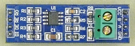
They are inexpensive but fairly reliable. Collected on the MAX485 chip.
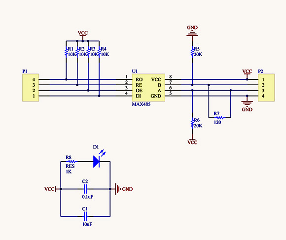
Connection with Arduino are held according to the scheme

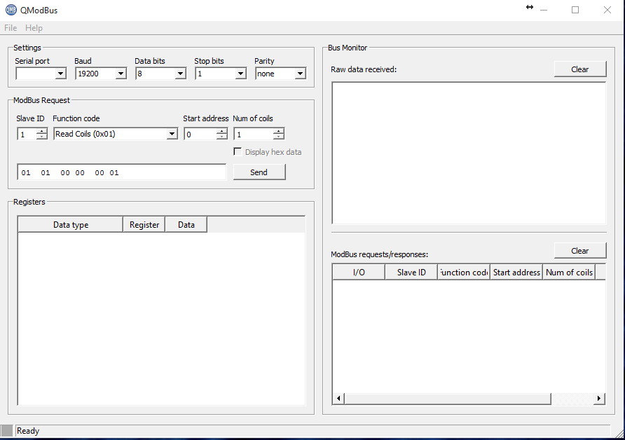
To emulate the master and slave during the development of the protocol implementation, I used two very good free programs.
QModBus - Lead Simulator
')
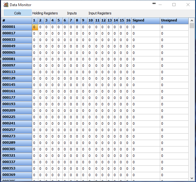
PeakHmiMBSerialSlave - Slave Simulator
And finally, a video tutorial on creating a master and slave in the FLProg program.
Ps. I thank the authors of the articles presented below, which helped me understand the Modbus protocol and implement this functionality.
Sources:
Modbus RTU for Dummies
Arduino & Modbus
Source: https://habr.com/ru/post/262521/
All Articles