The mystery of flicker noise unraveled
Long ago, when the diodes were still vacuum, J.V. Johnson first observed the atrial effect in the current of electron tubes, which he called “atrial or flicker noise.” Exactly 90 years have passed since then, and they continue to detect flicker noise in a wide variety of systems, from semiconductor devices to river flooding, from physics to sociology, but no one could explain the nature of its origin.
Even a Soviet film is about flicker noise.
')
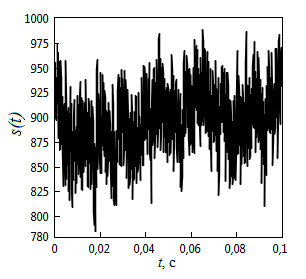
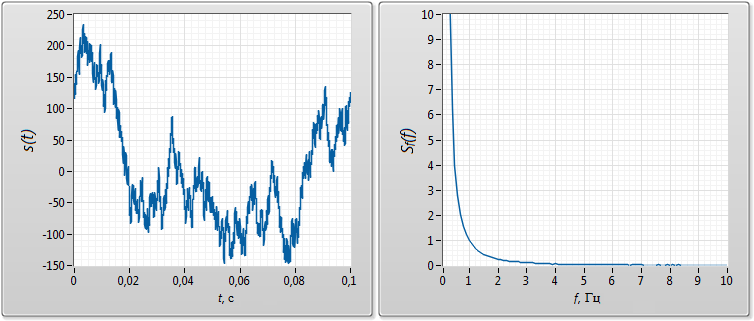
This is what flicker noise looks like:
Physicists, trying to explain the nature of this phenomenon, naturally look for it in the physics of the processes that occur, although they call it flicker noise an anomaly. Recall what we are taught in postgraduate courses in the “History and Philosophy of Science” courses: anomaly (which is flicker noise) is the result of the fundamental inability of the scientific paradigm to explain existing facts, that is, the problem must be sought in theory.
The theory in this case are spectral methods. Let's try to deal with these methods, maybe something is wrong with them?
By definition, flicker noise is a signal whose power spectral density (or simply the power spectrum) of which is described by the formula:

where K is a dimensional constant, γ is a dimensionless constant, which in most cases is close to unity (in the article we will consider only flicker noise with γ = 1).
Let's look at the power spectrum of flicker noise and try to see something in it.
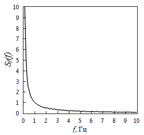
It is seen that the power in the frequency band from 1 Hz to infinity is equal to the power from 0 to 1 Hz. What is so special about these two frequency bands that their power is the same? These two bands are connected by the fact that their boundaries are reciprocal of each other, that is, 0 is 1 / infinity, and 1 is 1/1. And what is the reciprocal of frequency? This is a period.
I wonder why the spectral analysis uses only the spectral power density in frequency, maybe you should try to find the power spectral density over the period? At this place, everyone says - "why do we need to find from the period, nothing will change from this." Look at the drawing.
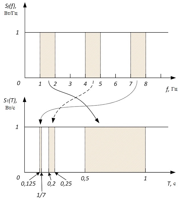
It can be seen from the figure that different period bands correspond to the same frequency band. Hence, the power spectrum over the period should be of a completely different form. Let us find the relationship between the spectral power densities by frequency and by period. The elementary power increment is:

where S f (f) is the power spectral density by frequency (f-SPM), S T (f) is the power spectral density by period (T-), T is the period.
The minus sign on the right side of formula (2) means that a positive increment in frequency corresponds to a negative increment over the period.
From formula (2) we obtain:

What will flicker noise look like now? Again the same:

Flicker noise is the only signal whose power spectrum looks the same both in frequency and period. If we take, for example, white noise, then its T-SPM will not be uniform over the period:

What, then, will the signal be uniform over the period? Yes, that's what:
This is Brownian noise, its T-SPM and f-SPM, respectively, are defined by the formulas:
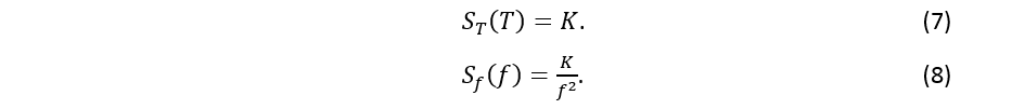
If we represent the Brownian noise as a sum of harmonics, then it is more convenient to use then not a Fourier series, but a series with a uniform step over the period:
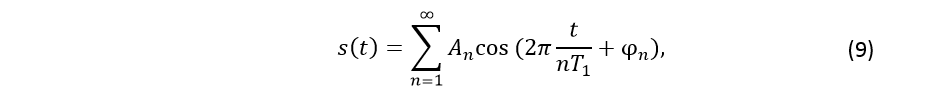
where A n is the amplitude of the n-th harmonic, T 1 is the period of the main harmonic, φ n is the phase of the n-th harmonic.
You can also do the animation with the summation of harmonics:
With the spectral power density over the period, you can experiment for a long time, but we will move on.
Equally uniform in frequency and period, based on formula (4), there can only be a signal that is equal to zero everywhere. What kind of noise is then considered a signal with a uniform spectrum? Let us try to imagine a signal with a uniform spectrum and at the same time not be attached to any step in frequency or period.
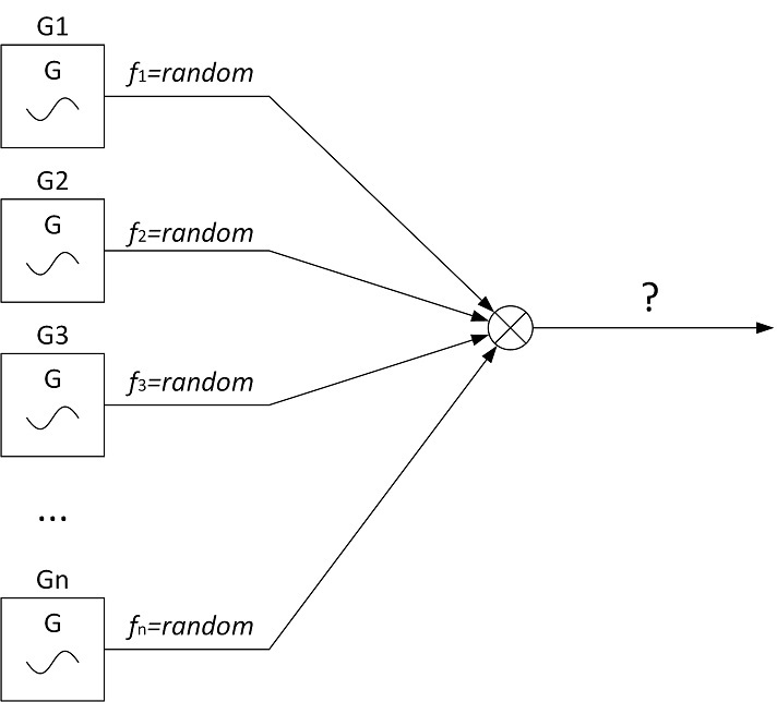
Imagine that a plant produces sinusoidal voltage generators of fixed frequency and fixed power. All manufactured generators have absolute repeatability in terms of the power of the generated signal, and this power is equal to P 0 . However, frequency repeatability is completely absent - each generator frequency can be equal to any value from zero to infinity (at least pHz, at least THz). Now we take a very large number of such generators and give signals from their outputs to the adder.
Scientific language
Here we consider such a process with infinite energy, that each implementation of it contains only one harmonic, while the power of each implementation is P 0 , and the frequency can take any value.
It is obvious that the signal at the output of the adder should have a uniform spectrum. What will be his power spectrum?
Anyone familiar with the basics of spectral analysis will immediately give the answer - “this is white noise, since by definition it is a signal with a uniform spectrum”. Let's check it out.
To begin with, you need to somehow link the power of each generator with its frequency. At this point, the question may arise - “what is there to connect, if it does not depend on the frequency?”, Then the counter question - does it also not depend on the period? As such a link, you can use the energy of one period of the sinusoid:

Generator power is equal to:

Now we will find a function that will show the dependence of the power of the generators on their frequency:

where E T (f) is the dependence of the energy of the period of the sinusoid of the generator on the frequency.
The power attributable to the df frequency band will be equal to:

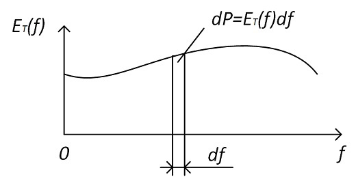
If we look at formulas (2) and (14), we will see that:

Remarkably, now from the formula (12) we find the power spectrum:

The signal at the output of the adder is flicker noise. The color of this noise is pink (for me, it is white).
And now the answer to the question of 90 years ago:
The mechanism of the appearance of flicker noise is very simple: if an object emits a harmonic signal of arbitrary frequency with a power of P 0 , then many such objects will emit a signal with a spectrum of flicker noise.
A true signal with a uniform spectrum is flicker noise. It is curious what kind of spectral coordinate it is, relative to which flicker noise looks uniform.
Suppose that the generated sinusoids differ in both frequency and power, then formula (16) is written in the following form:

where P (f) is the power of realization with frequency f.
Since for a process with a uniform spectrum, P (f) = P 0 , it is convenient to consider P (f) as the spectral power density with respect to a certain value of Φ (Φ-SPM):

By definition, the power spectral density must have the dimension of power divided by the dimension of the spectral coordinate. In this case, Φ-SPM has the dimension of power, therefore, its spectral coordinate Φ should be dimensionless. Thus, Φ-SPM will simultaneously be both the spectral power density and the frequency of the generator power. The power in the df frequency band must be equal to the power in the dΦ band:

From formulas (17), (18) and (19), we get:

and Φ is determined by the formula:

To exclude the logarithm of the dimensional value, we take:

where f 0 is a frequency equal to 1 Hz,
then:

I had to introduce a completely meaningless constant f 0 due to the fact that the logarithm of dimensional values in physicists causes a fatal error.
And now we can imagine flicker noise as a sum of harmonics with the same amplitudes:

where A n is the amplitude of the n-th harmonic, 1 - of the main harmonic, φ n is the phase of the n-th harmonic.
Make an animation:
You can still make the animation for the same initial phases:
If we combine formulas (4), (17), (18), we get a beautiful expression:

I will say a few words on quantum mechanics.
In addition to the spectral power density, there is also the spectral energy density (EIT). Their difference is that EIT is used for processes with finite energy, and SPM for processes with infinite energy. EIT characterizes the energy per unit frequency band. And what prevents us from doing the same for processes with finite energy? SPEs in different spectral coordinates will be related by a similar formula:

where W f (f) is the spectral energy density by frequency (f-SPE), W F (F) is the spectral energy density by Φ (Φ-SPE), W T (T) is the spectral energy density by period (T-SPE ).
The left side of the formula (26) does not remind you anything? This formula can be easily converted to a formula for quantum energy.

Let's imagine that the generators considered above produce signals with arbitrary frequencies and arbitrary powers, but the energy of these signals is finite. In nature, such generators, to put it mildly, are very common - these are electrons, and the signals they generate are energy quanta.
Φ-EIT at a specific frequency equals energy:

If f-SPE is taken to be Planck's constant, then formula (29) is transformed into a formula for quantum energy (28).
Since the Planck constant does not depend on frequency, it can be considered as a uniform f-SPE process, each realization of which corresponds to the emission of one energy quantum with an arbitrary frequency by an electron.
If we divide the f-SPE of an electromagnetic wave by Planck's constant, then we can obtain the dependence of the number of quanta of the wave on frequency. And so on…
Conclusion: flicker noise is a signal with a uniform spectrum, the spectrum of which is distorted by the Fourier transform .
I would be glad to any criticism of the article.
Appendix A
If the process is represented by the functions P (f) and ET (f):

then the power spectrum of such a process can be found as a derivative of P (f) in frequency:

The elementary increment is then determined by the formula:

In this case, a function appears that is equal to the derivative of the energy dependence over a period in frequency (with the dimension J / Hz).
Consider a process with the following ET (f):

If γ = 1, then the process under consideration has a uniform continuous spectrum (in accordance with formula (A.1)).
We will determine by the formula (A.3) the power spectrum of the process corresponding to the formula (A.5):

Denote:

and get the formula (1):

The closer γ is to unity, the more uniform the spectrum, however, K decreases. In the limit, when γ = 1, the power spectrum of flicker noise is obtained with K = 0.
For the power spectrum over the period, a similar result is obtained.
If γ = 0, then the power spectrum will correspond to white noise. From formulas (A.5) and (A.1) it can be seen that the process with γ = 0 (white noise) does not have a uniform spectrum:

then the power spectrum of such a process can be found as a derivative of P (f) in frequency:
The elementary increment is then determined by the formula:
In this case, a function appears that is equal to the derivative of the energy dependence over a period in frequency (with the dimension J / Hz).
Consider a process with the following ET (f):
If γ = 1, then the process under consideration has a uniform continuous spectrum (in accordance with formula (A.1)).
We will determine by the formula (A.3) the power spectrum of the process corresponding to the formula (A.5):
Denote:
and get the formula (1):
The closer γ is to unity, the more uniform the spectrum, however, K decreases. In the limit, when γ = 1, the power spectrum of flicker noise is obtained with K = 0.
For the power spectrum over the period, a similar result is obtained.
If γ = 0, then the power spectrum will correspond to white noise. From formulas (A.5) and (A.1) it can be seen that the process with γ = 0 (white noise) does not have a uniform spectrum:
Appendix B
Consider the frequency grid with a uniform step, tending to zero. Since the frequency step tends to zero, such a grid of frequencies contains all possible frequencies and they are defined at the points n * df.

Consider also a grid of periods with a uniform step, tending to zero. Since the periodic step tends to zero, such a grid of periods contains all possible periods and they are defined at the points n * dT.
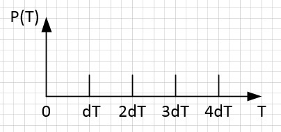
If we compare the grid of frequencies and the grid of periods, then we can see that there are periods with which it is impossible to compare the frequency (fall on the interval from n * df to (n + 1) * df), and vice versa.

If the frequency cannot be compared to the period, and also if the period cannot be compared to the frequency, then they should be removed from the corresponding grid, since they do not exist. That is, each grid contains extra frequencies and periods. If we remove all the frequencies and periods for which it is impossible to compare the period and the frequency, we will get some new uneven frequency step, equal to the uneven step over the period. Such a step corresponds to a uniform step in the logarithm of the frequency, equal in absolute value to a uniform step in the logarithm of the period. A process with a spectrum that is uniform in the logarithm of frequency is flicker noise.
Consider also a grid of periods with a uniform step, tending to zero. Since the periodic step tends to zero, such a grid of periods contains all possible periods and they are defined at the points n * dT.
If we compare the grid of frequencies and the grid of periods, then we can see that there are periods with which it is impossible to compare the frequency (fall on the interval from n * df to (n + 1) * df), and vice versa.
If the frequency cannot be compared to the period, and also if the period cannot be compared to the frequency, then they should be removed from the corresponding grid, since they do not exist. That is, each grid contains extra frequencies and periods. If we remove all the frequencies and periods for which it is impossible to compare the period and the frequency, we will get some new uneven frequency step, equal to the uneven step over the period. Such a step corresponds to a uniform step in the logarithm of the frequency, equal in absolute value to a uniform step in the logarithm of the period. A process with a spectrum that is uniform in the logarithm of frequency is flicker noise.
Appendix B
It is known that the delta function has a uniform spectrum. Let us determine its power spectral density by frequency and by period.
The coefficients of the Fourier series in a complex form are determined by the formula:

where ω1 is the main frequency.
If s (t) is a delta function, then all coefficients Ck will take the same value, regardless of k, and the value of the fundamental frequency can be anything.
But nothing prevents you from using any other sequence instead of a sequence of integers. If we take, for example, the sequence of numbers, the inverse of an integer:

then the formula (B.1) takes the form

where T1 is the main period,
and a discrete spectrum will be obtained with a uniform step over the period. In this case, for the delta function, the value of the coefficients Ck also takes the same value, and the value of the period of the main harmonic can also be any.
If we turn to continuous power spectra in terms of frequency and period, we obtain that both power spectra are a function independent of their argument, which contradicts formula (4). It turns out that the power spectrum of the delta function depends on the method of its determination.
Let's try to determine which values of frequencies and periods are possible at all. Frequency and period can take any value from 0 to infinity for two reasons:
1) The time axis is continuous - the frequency can be increased infinitely many times, respectively, the period can be reduced infinitely many times.
2) The time axis is infinite - the frequency can be reduced infinitely many times, respectively, the period can be increased infinitely many times.
We first define the spectrum of a time-limited, periodically extended and time-discrete delta function. Then we strive to zero the discretization step and to infinity the repetition period of the delta function, as a result we get a continuous spectrum of the delta function.
It is known that a periodic in the time domain signal has a discrete spectrum. The spectrum of such a signal is represented as a grid of frequencies obtained by multiplying a frequency equal to f0 = 1 / (signal period) by an integer. In the case of the delta function, we obtain a set of harmonics with a uniform frequency step with the same amplitudes.
It is known that a discrete in the time domain signal has a periodic spectrum. There are no restrictions on the possible values of frequencies (except for the condition that the frequency in the spectrum should be less than the Nyquist frequency for recovery).
Consider periodic discrete signals:
a) If the signal is discrete, then it is defined only at some specific points: tn = n * Δt, where n is an integer, Δt is a discretization step.
b) If the signal is periodic, then all its values are repeated after a period of time: s (t) = s (t + T), where T is the signal period.
c) If the signal is discrete and periodic, then all its values are repeated over a period of time that is a multiple of the sampling step s (tn) = s (tn + Td), where Td is the signal period, which is the sum of the integer Δt. This is explained by the fact that a signal with a period consisting of a fractional number Δt will not repeat its value after a period, since it will fall on a non-existent time. It turns out that the restriction on the possible values of frequencies is still there.
For example, if a harmonic signal with a frequency of 1.5 Hz is digitized with a sampling frequency of 10 Hz, then a periodic signal with a frequency of 0.5 Hz is obtained.
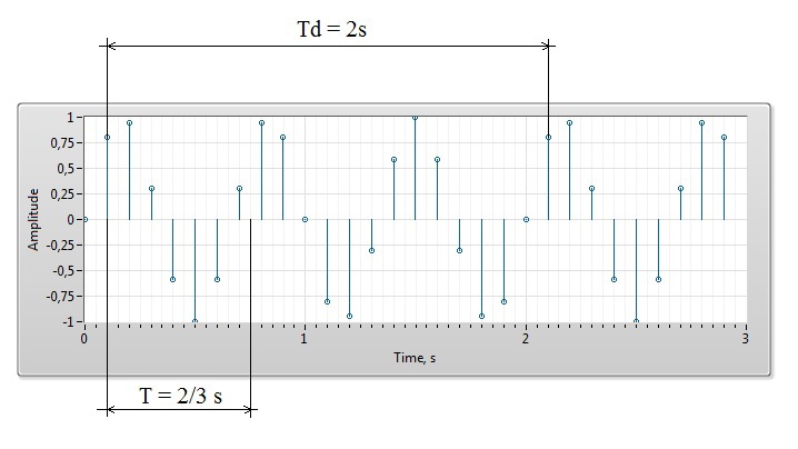
Thus, a discrete signal in time can be periodic only with a period that is a multiple of the sampling step Δt, and the spectrum of such a signal can consist only of periods Tn = n * Δt, where n is an integer. In the case of the delta function, we obtain a set of harmonics with a uniform step over the period with the same amplitudes.
Now we define the spectrum of a time-limited, periodically extended and time-discrete delta function. Such a spectrum can consist only of frequencies fn, multiples of f0 and periods Tn, multiples of Δt. If one of the frequencies fn does not coincide with any of the 1 / Tn, then this is no longer the frequency fn, but some other one from the set 1 / Tn. Thus, if the frequency fn fails to match any of the periods from the Tn set, then it should be removed from the fn set, since a signal with such a frequency cannot be realized at a given sampling step. If we remove from the grid of frequencies all frequencies that cannot be compared to a period, then we obtain a new step that is uneven in frequency, equal to a period uneven step. Such an uneven pitch is a uniform step over the logarithm of frequency. A signal with a spectrum that is uniform in logarithm of the spectrum is flicker noise. If we strive to zero the discretization step and to infinity the repetition period of the delta functions, then we get a continuous spectrum of the delta function, which coincides with the spectrum of flicker noise.
The coefficients of the Fourier series in a complex form are determined by the formula:
where ω1 is the main frequency.
If s (t) is a delta function, then all coefficients Ck will take the same value, regardless of k, and the value of the fundamental frequency can be anything.
But nothing prevents you from using any other sequence instead of a sequence of integers. If we take, for example, the sequence of numbers, the inverse of an integer:
then the formula (B.1) takes the form
where T1 is the main period,
and a discrete spectrum will be obtained with a uniform step over the period. In this case, for the delta function, the value of the coefficients Ck also takes the same value, and the value of the period of the main harmonic can also be any.
If we turn to continuous power spectra in terms of frequency and period, we obtain that both power spectra are a function independent of their argument, which contradicts formula (4). It turns out that the power spectrum of the delta function depends on the method of its determination.
Let's try to determine which values of frequencies and periods are possible at all. Frequency and period can take any value from 0 to infinity for two reasons:
1) The time axis is continuous - the frequency can be increased infinitely many times, respectively, the period can be reduced infinitely many times.
2) The time axis is infinite - the frequency can be reduced infinitely many times, respectively, the period can be increased infinitely many times.
We first define the spectrum of a time-limited, periodically extended and time-discrete delta function. Then we strive to zero the discretization step and to infinity the repetition period of the delta function, as a result we get a continuous spectrum of the delta function.
It is known that a periodic in the time domain signal has a discrete spectrum. The spectrum of such a signal is represented as a grid of frequencies obtained by multiplying a frequency equal to f0 = 1 / (signal period) by an integer. In the case of the delta function, we obtain a set of harmonics with a uniform frequency step with the same amplitudes.
It is known that a discrete in the time domain signal has a periodic spectrum. There are no restrictions on the possible values of frequencies (except for the condition that the frequency in the spectrum should be less than the Nyquist frequency for recovery).
Consider periodic discrete signals:
a) If the signal is discrete, then it is defined only at some specific points: tn = n * Δt, where n is an integer, Δt is a discretization step.
b) If the signal is periodic, then all its values are repeated after a period of time: s (t) = s (t + T), where T is the signal period.
c) If the signal is discrete and periodic, then all its values are repeated over a period of time that is a multiple of the sampling step s (tn) = s (tn + Td), where Td is the signal period, which is the sum of the integer Δt. This is explained by the fact that a signal with a period consisting of a fractional number Δt will not repeat its value after a period, since it will fall on a non-existent time. It turns out that the restriction on the possible values of frequencies is still there.
For example, if a harmonic signal with a frequency of 1.5 Hz is digitized with a sampling frequency of 10 Hz, then a periodic signal with a frequency of 0.5 Hz is obtained.
Thus, a discrete signal in time can be periodic only with a period that is a multiple of the sampling step Δt, and the spectrum of such a signal can consist only of periods Tn = n * Δt, where n is an integer. In the case of the delta function, we obtain a set of harmonics with a uniform step over the period with the same amplitudes.
Now we define the spectrum of a time-limited, periodically extended and time-discrete delta function. Such a spectrum can consist only of frequencies fn, multiples of f0 and periods Tn, multiples of Δt. If one of the frequencies fn does not coincide with any of the 1 / Tn, then this is no longer the frequency fn, but some other one from the set 1 / Tn. Thus, if the frequency fn fails to match any of the periods from the Tn set, then it should be removed from the fn set, since a signal with such a frequency cannot be realized at a given sampling step. If we remove from the grid of frequencies all frequencies that cannot be compared to a period, then we obtain a new step that is uneven in frequency, equal to a period uneven step. Such an uneven pitch is a uniform step over the logarithm of frequency. A signal with a spectrum that is uniform in logarithm of the spectrum is flicker noise. If we strive to zero the discretization step and to infinity the repetition period of the delta functions, then we get a continuous spectrum of the delta function, which coincides with the spectrum of flicker noise.
Source: https://habr.com/ru/post/262015/
All Articles