Remote control via Ethernet: M2M technology using a combination of KBX-3D and Laurent-2 modules
Often a situation arises when an Ethernet network is laid in a room or even a building, and a desire arises with its help to transfer a simple command from one room to another. For example, from the watchman’s room by pressing the button open the door in the backyard. Now it is possible to do this without using computers and servers, without writing additional programs, etc. It is enough to connect the command and executive modules of Laurent to the network, supply power and make small settings. After that, the modules will be able to communicate with each other directly.
This article describes the M2M technology (Module-to-Module) on the example of setting up communication between Laurent-2 and KBX-3D .

')
The M2M technology allows modules to communicate with each other with text data, for example, Ke-control commands without the participation of an external server, i.e. offline. For example, it is possible to automatically send a command to another module on the same network when an event occurs. At the same time, external servers or programs are not needed - everything can be done using the CAT + M2M bundle in the module itself.
For example, let's consider the following problem:
Two modules are connected to the local network: Laurent-2 and KBX-3D. It is necessary that when the 1st input line of the Laurent-2 module is closed, the KBX-3D module relay is perekchelivalo. An important condition is the absence of an external server. All must do the module itself without “external” help.
Just in case, at the beginning we will consider the procedure of connecting several modules to the same network. The subtlety is that all modules by default have the same IP and MAC addresses. For normal operation of network devices, these parameters must be different for devices on the network. Therefore, for our example, let's change the network details of the Laurent-2 module, and leave the KBX-3D settings unchanged.
Go to the Laurent-2 Web interface (default address: 192.168.0.101). Go to the settings section and change the IP and MAC addresses. Install IP 192.168.0.102 and MAC 0.4.163.0.0.12.

In order for the changes to take effect, you must reset the module, for example, through a power reset. After this, the module will be available at the new address and will not conflict with the MAC addresses with the KBX-3D module, the settings of which we left unchanged.
Create a CAT event on the Laurent-2 module. If the voltage level changes on the input line IN_1 (for example, the line will be shorted to + 5V from a button or some contact sensor), then in response to this event, Ke control commands will be sent to the IP address of the KBX-3D module.

In the command line, two are indicated at once - the command to enter the password for accessing the KBX-3D module ($ KE, PSW, SET) and the command to control the relay ($ KE, REL). At the end of each command there must be a ';' - when sending, it will be replaced with carriage return and newline characters (CR + LF).
The command with the password is transmitted because by default, the security system is enabled in the modules, which blocks the execution of module resource management commands until the access password is entered.
If the security system is disabled on the KBX-3D module, there will be no need to send the first command with a password.
On the Laurent-2 module, it is recommended to enable a software contact bounce suppressor. If this is not done, then using a mechanical key or a button connected to the input line when pressed instead of one event, several dozen are formed at once due to the “bounce” of the mechanical connection triggering. Accordingly, an attempt will be made to send dozens of times the list of commands for execution, which is not always acceptable.

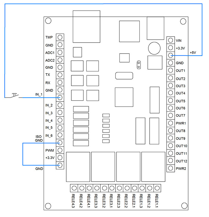
Now everything is ready. It is enough to send a signal from the button (high level) to the input line IN_1, the CAT system will work, the set of specified commands will be sent to the KBX-3D module and the first relay of the KBX-3D module will be turned on.
For convenience of connecting the button to the input line, it is recommended to connect the GND and ISO_GND lines. The point is that the input lines of the modules are opto-isolated. There is no special need for buttons and you can send a signal from the board itself to the input line (for example, from the +5 V terminal). For this, the ground of the input line and board power supply must be common. Which is achieved by connecting GND and ISO_GND.
The example is simple, but it provides ample opportunity to control your equipment.
This article describes the M2M technology (Module-to-Module) on the example of setting up communication between Laurent-2 and KBX-3D .
')
The M2M technology allows modules to communicate with each other with text data, for example, Ke-control commands without the participation of an external server, i.e. offline. For example, it is possible to automatically send a command to another module on the same network when an event occurs. At the same time, external servers or programs are not needed - everything can be done using the CAT + M2M bundle in the module itself.
For example, let's consider the following problem:
Two modules are connected to the local network: Laurent-2 and KBX-3D. It is necessary that when the 1st input line of the Laurent-2 module is closed, the KBX-3D module relay is perekchelivalo. An important condition is the absence of an external server. All must do the module itself without “external” help.
Just in case, at the beginning we will consider the procedure of connecting several modules to the same network. The subtlety is that all modules by default have the same IP and MAC addresses. For normal operation of network devices, these parameters must be different for devices on the network. Therefore, for our example, let's change the network details of the Laurent-2 module, and leave the KBX-3D settings unchanged.
Go to the Laurent-2 Web interface (default address: 192.168.0.101). Go to the settings section and change the IP and MAC addresses. Install IP 192.168.0.102 and MAC 0.4.163.0.0.12.
In order for the changes to take effect, you must reset the module, for example, through a power reset. After this, the module will be available at the new address and will not conflict with the MAC addresses with the KBX-3D module, the settings of which we left unchanged.
Create a CAT event on the Laurent-2 module. If the voltage level changes on the input line IN_1 (for example, the line will be shorted to + 5V from a button or some contact sensor), then in response to this event, Ke control commands will be sent to the IP address of the KBX-3D module.
In the command line, two are indicated at once - the command to enter the password for accessing the KBX-3D module ($ KE, PSW, SET) and the command to control the relay ($ KE, REL). At the end of each command there must be a ';' - when sending, it will be replaced with carriage return and newline characters (CR + LF).
The command with the password is transmitted because by default, the security system is enabled in the modules, which blocks the execution of module resource management commands until the access password is entered.
If the security system is disabled on the KBX-3D module, there will be no need to send the first command with a password.
On the Laurent-2 module, it is recommended to enable a software contact bounce suppressor. If this is not done, then using a mechanical key or a button connected to the input line when pressed instead of one event, several dozen are formed at once due to the “bounce” of the mechanical connection triggering. Accordingly, an attempt will be made to send dozens of times the list of commands for execution, which is not always acceptable.
Now everything is ready. It is enough to send a signal from the button (high level) to the input line IN_1, the CAT system will work, the set of specified commands will be sent to the KBX-3D module and the first relay of the KBX-3D module will be turned on.
For convenience of connecting the button to the input line, it is recommended to connect the GND and ISO_GND lines. The point is that the input lines of the modules are opto-isolated. There is no special need for buttons and you can send a signal from the board itself to the input line (for example, from the +5 V terminal). For this, the ground of the input line and board power supply must be common. Which is achieved by connecting GND and ISO_GND.
The example is simple, but it provides ample opportunity to control your equipment.
Source: https://habr.com/ru/post/261957/
All Articles