Introducing the Freescale T1040RDB debug card for industrial network switches

In pursuit of the minimum price and development time of complex network devices, network processor manufacturers strive to produce the most integrated solutions, which simplifies the development of hardware and software. An example of this approach is the 64-bit processors Freescale T1040 and T1020 with built-in gigabit switch.
The T10xx family is ideally suited for managing and processing traffic in devices such as industrial routers, switches, access points, firewalls, DPI systems, and other network equipment.
')
The T1040RDB debug card, which we will study in this article, is a hardware platform based on the Freescale QorIQ T1040 processor with four e5500 cores and speeds up to 1.4 GHz.

Front Panel T1040RDB
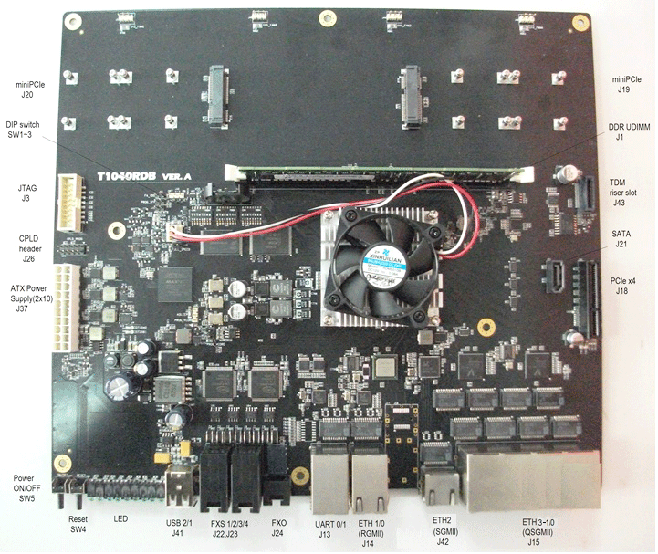
Interfaces of the T1040RDB motherboard
The figure below shows the high-level block diagram of the T1040RDB:
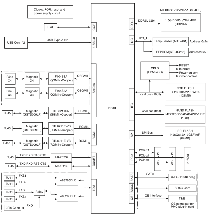
Key Features T1040RDB:
- Processor platform Freescale QorIQ
- QorIQ T1040 telecommunications processor with four e5500 cores operating at 1.4 GHz
- Memory subsystem
- DDR3L SDRAM
- 1 DIMM slot supporting up to 2 GB
- Support DDR3 1600 UDIMM / RDIMM
- NOR flash memory
- 128 MB 16-bit NOR flash memory, MICRON: JS28F00AM29EWHA
- NAND flash
- 1 GB SLC NAND flash memory, MICRON: MT29F8G08ABABAWP-ITX: B
- SD card support
- SATA interface
- DDR3L SDRAM
- PCIe
- One PCIe-x4 slot
- Two mini-PCIe slots
- USB 2.0
- Dual USB slot (connected to USB PHY)
- Gigabit ethernet
- ETH0 - ETH 1: Connected to two independent RGMII PHY - RTL8211E
- ETH 2 :: Connected to SGMII PHY - RTL8211DN
- ETH 3 - ETH10: Connected to two independent QSGMII PHY - F104
- UART
- Support for two UARTs, up to 115200 bps for console output; use dual RJ45 connector for two ports
- TDM
- Supports one FXO and four FXS telephony ports
Linux build
The debug board T1040RDB comes with pre-installed software, but for full development you will need to assemble the firmware from the provided SDK. As a working environment, we use a PC with Ubuntu 12.04.4 LTS installed on it.
The SDK is delivered as an image with the following name: QorIQ-SDK-T2080V1.1-T1040V0.3-SOURCE-20140422-yocto.iso
To install on a working PC, just run the installation script:
./install The installation will be executed in the following directory:
cd ~/QorIQ-SDK-T2080V1.1-T1040V0.3-20140422-yocto Next - install the necessary dependencies on your PC:
./scripts/host-prepare.sh To configure the assembly for our fee, we perform:
./fsl-setup-poky -m t1040rdb The firmware build itself is performed using bitbake with an indication of the required composition of the root file system:
bitbake fsl-image-core The finished images will be copied to the directory:
QorIQ-SDK-T2080V1.1-T1040V0.3-20140422-yocto/build_t1040rdb_release/tmp/deploy/images Connect to console
- Connect the RS-232 cable port T1040RDB "UART0" and working PC
- Open the Terminal program on your work PC to communicate with the T1040RDB
- The configuration of the serial port of the work computer must be as follows:
- Speed: 115200 bps
- Amount of data bits: 8
- Parity check: no
- Number of stop bits: 1
- Flow control: hardware or without flow control
Linux boot
Next, we consider loading the T1040RDB from the TFTP server installed on the working PC. To do this, move the uImage - 3.8-r11.1-t1040rdb-20150603132854.bin, uImage - 3.8-r11.1-t1040rdb-20150603132854.dtb, fsl-image-core-t1040rdb-20150603132854.rootfs.ext2.gz.u -boot to the TFTP server directory.
To boot, you must install the following parameters in the u-boot console and specify the boot command with TFTP:
setenv serverip 192.168.1.10 setenv ipaddr 192.168.1.1 setenv ethact FM1@DTSEC4 setenv baudrate 115200 setenv bootfile uImage--3.8-r11.1-t1040rdb-20150603132854.bin setenv consoledev ttyS0 setenv fdtfile uImage--3.8-r11.1-t1040rdb-20150603132854.dtb setenv fdtaddr c00000 setenv loadaddr 1000000 setenv othbootargs ramdisk_size=960000 setenv ramboot 'setenv bootargs root=/dev/ram rw console=$consoledev,$baudrate $othbootargs;tftp $ramdiskaddr $ramdiskfile;tftp $loadaddr $bootfile;tftp $fdtaddr $fdtfile;bootm $loadaddr $ramdiskaddr $fdtaddr' setenv ramdiskaddr 2000000 setenv ramdiskfile fsl-image-core-t1040rdb-20150603132854.rootfs.ext2.gz.u-boot Run the Linux boot command:
run ramboot Upon successful receipt of boot files from TFTP, the following message will appear in the console:
## Booting kernel from Legacy Image at 01000000 ... Image Name: Linux-3.8.13-rt9-QorIQ-SDK-T2080 Image Type: PowerPC Linux Kernel Image (gzip compressed) Data Size: 4290895 Bytes = 4.1 MiB Load Address: 00000000 Entry Point: 00000000 Verifying Checksum ... OK ## Loading init Ramdisk from Legacy Image at 02000000 ... Image Name: fsl-image-core-t1040rdb-20150603 Image Type: PowerPC Linux RAMDisk Image (gzip compressed) Data Size: 27520425 Bytes = 26.2 MiB Load Address: 00000000 Entry Point: 00000000 Verifying Checksum ... OK ## Flattened Device Tree blob at 00c00000 Booting using the fdt blob at 0xc00000 Uncompressing Kernel Image ... OK Loading Ramdisk to 2e5c1000, end 2ffffda9 ... OK Loading Device Tree to 03fe1000, end 03fff71e ... OK The full OS boot log is skipped to save reader time.
Connect to the Linux command line:
login: root root@t1040rdb:~# , : root@t1040rdb:~# uname -a Linux t1040rdb 3.8.13-rt9-QorIQ-SDK-T2080V1.1-T1040V0.3 #1 SMP Wed Jun 3 17:31:19 FET 2015 ppc GNU/Linux In the assembled firmware there are standard utilities for checking the network bandwidth of iperf and netperf. Let's perform basic throughput checks:
root@t1040rdb:~# ifconfig fm1-gb3 up # ETH0 root@t1040rdb:~# ifconfig fm1-gb3 192.168.1.1 root@t1040rdb:~# iperf -c 192.168.1.10 ------------------------------------------------------------ Client connecting to 192.168.1.10, TCP port 5001 TCP window size: 21.3 KByte (default) ------------------------------------------------------------ [ 3] local 192.168.1.1 port 40315 connected with 192.168.1.10 port 5001 [ ID] Interval Transfer Bandwidth [ 3] 0.0-10.0 sec 1.09 GBytes 935 Mbits/sec Thus, within a few hours we received a working board with Yocto Linux for further development and debugging of telecommunications software.
Thanks for attention!
Another good article on this topic: Introduction to the capabilities of the Realtek RTL 8332M switch processor .
Source: https://habr.com/ru/post/261909/
All Articles