STM32, C ++ and FreeRTOS. Development from scratch. Part 2
Introduction
In the last publication of STM32, C ++ and FreeRTOS. Development from scratch. Part 1 I stopped on how
SR0: The device should measure three parameters (have three variables): microprocessor temperature , voltage VDDA , voltage from a variable resistor
SR1: The device should display the value of these variables on the indicator .
SR2: The unit of measurement for the microprocessor temperature is degrees Celsius, for the other parameters it is volts.
SR3: When you press button 1 , the display should show a screen with the next variable to be measured,
SR4: When you press button 1, LED 1 must change its state
SR5: When you press button 2 , the display should change the display mode of variables from constantly showing the variable to consecutive (changing screens every 1.5 seconds) when you next press from consecutive to constant,
SR6: When you press button 2, LED 2 should change its state.
SR7: LED 3 should blink once every 1 second.
Development: ADC
Having decided that I had comprehended all the wisdom of the new microcontrollers, I decided to take the most ambitious requirement of the SR0 - in fact, this is the main functionality of the device - to measure 3 quantities.
For a start it was necessary to deal with the ADC. Having decided to take this block on the fly, especially without reading the documentation for the microcontroller, armed with a special tool Crt-C and Ctr-V, I drew a copy of the LED control architectures and buttons.
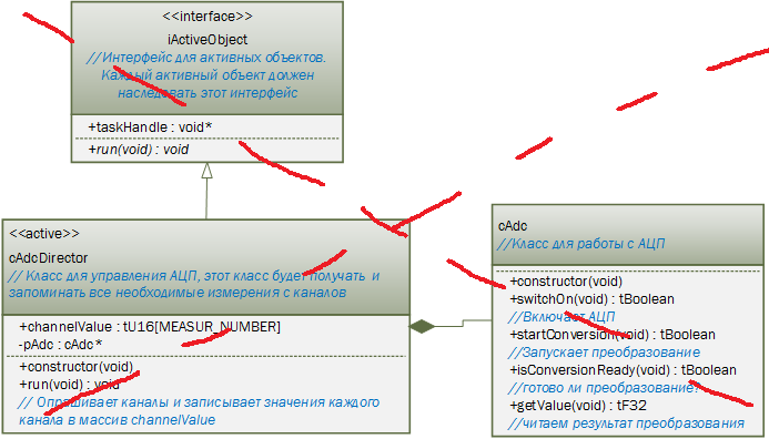
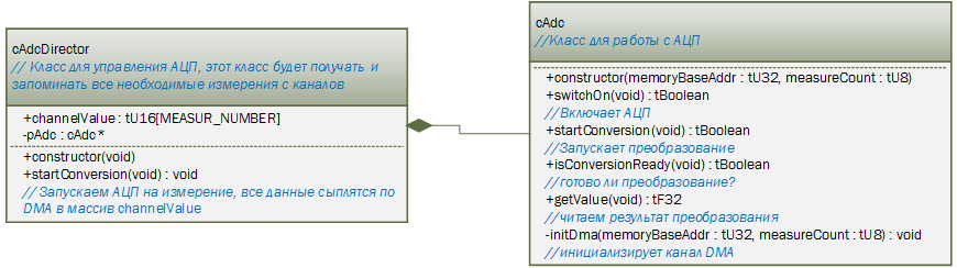
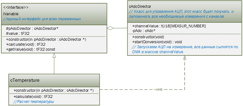
But starting to realize this wonderful picture, which in general is a very working one, I became interested in reading the documentation and realized that you can do it without an active object at all using the DMA channel. Of course, this architecture will already be processor dependent, for the simple reason that not all microcontrollers have such a block, but I thought it would be interesting and useful to show how to simplify things a little using the microcontroller features.
And redid everything like this:
')
All architecture is ready, and here I am stuck. It turned out that adjusting the ADC is a little more complicated than the ports, and I have not hard measured the voltage from the variable resistor. The temperature is there, Vdda is there, but with a variable switch. Configuring the ADC helped again the same resource that helped me to make the project STM32L. ADC - Analog-to-Digital Converter and STM32L. DMA controller. And to deal with the variable volume demo project, downloaded with the documentation for the Olimex board. It turned out that he just had to connect a separate leg PortD.Pin1 processor. As usual, I threw all the iron settings into __low_level_init ()
ADC and DMA settings
// () PORTD_PIN1 GPIOD->MODER |= GPIO_MODER_MODER1_0; GPIOD->PUPDR |= GPIO_PUPDR_PUPDR1_0; GPIOD->OSPEEDR |= GPIO_OSPEEDER_OSPEEDR1; // , 12 , 16- , 17 - VDDA, // 22 - , // , , , // EOC, EOC , http://chipspace.ru/stm32l-discovery-adc/ // 16() 17(vdda) // 22() , 2- vdda, 3- ADC1->CR2 |= (ADC_CR2_DELS_2 | ADC_CR2_CONT); ADC1->CR1 |= ADC_CR1_SCAN; // GPIOE.7 - GPIOE->MODER |= GPIO_MODER_MODER7; //3 ADC1->SQR1 |= ADC_SQR1_L_1; // ADC_IN 16 1 , 305 // ADC_IN 17 2 , 305 // ADC_IN 22 3 , 305 ADC1->SQR5 |= ADC_SQR5_SQ1_4 | ADC_SQR5_SQ2_0 | ADC_SQR5_SQ2_4 | ADC_SQR5_SQ3_1 | ADC_SQR5_SQ3_2 | ADC_SQR5_SQ3_4; // 16 17 22 301 279 ADC1->SMPR2 |= ADC_SMPR2_SMP16 | ADC_SMPR2_SMP17_2; ADC1->SMPR1 |= ADC_SMPR1_SMP22_2; // VDDA ADC->CCR |= ADC_CCR_TSVREFE; // DMA ADC1->CR2 |= (ADC_CR2_DMA | ADC_CR2_DDS); // DMA // - , . DMA1_Channel1->CCR &= ~DMA_CCR1_DIR; // . DMA1_Channel1->CCR &= ~DMA_CCR1_PINC; // . DMA1_Channel1->CCR |= DMA_CCR1_MINC; // - 16 . DMA1_Channel1->CCR |= DMA_CCR1_PSIZE_0; // - 16 DMA1_Channel1->CCR |= DMA_CCR1_MSIZE_0; // - (Very High) DMA1_Channel1->CCR |= DMA_CCR1_PL; DMA1_Channel1->CCR |= DMA_CCR1_CIRC; The class implementation files themselves:
adc.h
#include "types.h" // #define SENSORTEMPERATURE_CHANNEL 0 #define VDDA_CHANNEL 1 #define TRIMMER_CHANNEL 2 class cAdc { public: explicit cAdc(const tU32 memoryBaseAddr, const tU8 measureCount); tBoolean switchOn(void); tBoolean startConversion(void); tBoolean isConversionReady(void); tF32 getValue(void) const; private: void initDma(const tU32 memoryBaseAddr, const tU8 measureCount); }; adc.cpp
#include <stm32l1xx.h> // STM2 #include "adc.h" // #include "susuassert.h" //for ASSERT #include "bitutil.h" // SETBIT, CLRBIT #define ADC1_DR_ADDRESS ((tU32)0x40012458) /******************************************************************************* * Function: constructor * Description: DMA RAM, * ******************************************************************************/ cAdc::cAdc(const tU32 memoryBaseAddr, const tU8 measureCount) { ASSERT(measureCount != 0); this->initDma(memoryBaseAddr, measureCount); } /******************************************************************************* * Function: switchOn * Description: ******************************************************************************/ tBoolean cAdc::switchOn(void) { tBoolean result = FALSE; // , 299 CD00240194.pdf SETBIT(ADC1->CR2, ADC_CR2_ADON); result = tBoolean(CHECK_BIT_SET(ADC1->SR, ADC_SR_ADONS)); return result; } /******************************************************************************* * Function: startConversion() * Description: ******************************************************************************/ tBoolean cAdc::startConversion(void) { tBoolean result = FALSE; // , 299 CD00240194.pdf SETBIT(ADC1->CR2, ADC_CR2_SWSTART); result = tBoolean(CHECK_BIT_SET(ADC1->SR, ADC_SR_STRT)); return result; } /******************************************************************************* * Function: getValue() * Description: ******************************************************************************/ tF32 cAdc::getValue(void) const { tF32 result = ADC1->DR; return result; } /******************************************************************************* * Function: isConversionReady() * Description: ? ******************************************************************************/ tBoolean cAdc::isConversionReady(void) { tBoolean result = tBoolean(CHECK_BIT_SET(ADC1->SR, ADC_SR_EOC)); return result; } /******************************************************************************* * Function: initDma() * Description: DMA ******************************************************************************/ void cAdc::initDma(const tU32 memoryBaseAddr, const tU8 measureCount) { // - . DMA1_Channel1->CPAR = ADC1_DR_ADDRESS; // - RAM. DMA1_Channel1->CMAR = memoryBaseAddr; DMA1_Channel1->CNDTR = measureCount; // DMA SETBIT(DMA1_Channel1->CCR, DMA_CCR1_EN); } adcdirector.h
#include "adc.h" // cAdc #define MEASUR_NUMBER (tU8) 3 class cAdcDirector { public: explicit cAdcDirector(void); void startConversion(void); __IO uint16_t channelValue[MEASUR_NUMBER]; // private: cAdc *pAdc; }; adcdirector.cpp
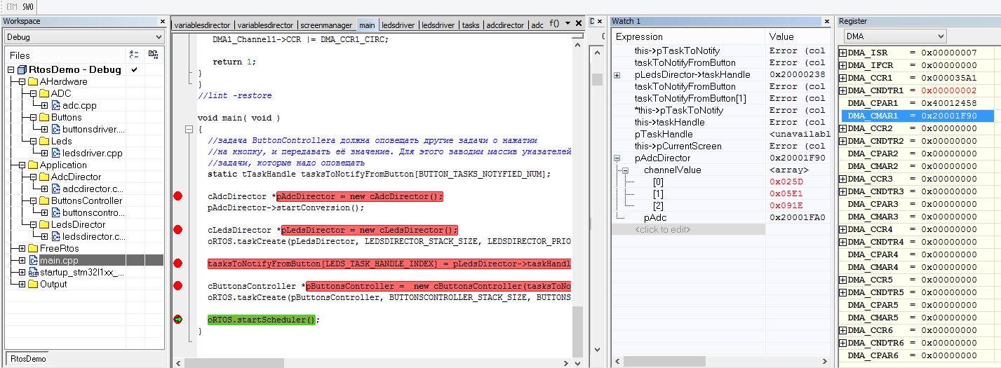
#include "adcdirector.h" // /******************************************************************************* * Function: constructor * Description: , RAM, * DMA . ******************************************************************************/ cAdcDirector::cAdcDirector(void) { this->pAdc = new cAdc((tU32)&channelValue[0], MEASUR_NUMBER); this->pAdc->switchOn(); } /******************************************************************************* * Function: startConversion * Description: , DMA * channelValue ******************************************************************************/ void cAdcDirector::startConversion(void) { this->pAdc->startConversion(); } It was possible to check the work only under the debugger, because I have no output to the indicator yet. But before that you need to add the creation of a new instance class in main ()
main ()
void main( void ) { // ButtonControllera // , . //, static tTaskHandle tasksToNotifyFromButton[BUTTON_TASKS_NOTYFIED_NUM]; cAdcDirector *pAdcDirector = new cAdcDirector(); pAdcDirector->startConversion(); cLedsDirector *pLedsDirector = new cLedsDirector(); oRTOS.taskCreate(pLedsDirector, LEDSDIRECTOR_STACK_SIZE, LEDSDIRECTOR_PRIORITY, "Leds"); tasksToNotifyFromButton[LEDS_TASK_HANDLE_INDEX] = pLedsDirector->taskHandle; cButtonsController *pButtonsController = new cButtonsController(tasksToNotifyFromButton, BUTTON_TASKS_NOTYFIED_NUM); oRTOS.taskCreate(pButtonsController, BUTTONSCONTROLLER_STACK_SIZE, BUTTONSCONTROLLER_PRIORITY, "Buttons"); oRTOS.startScheduler(); } I launched it for debugging and got the following image: As you can see, all 3 values in the channelValue [] array have changed and are highlighted in red. I didn’t check the values, but on a vskidku - something approximately similar.
As usual, the project was saved here: ADC, buttons and LEDs in IAR 6.50
Development: Variables
And so the ADC seems to be working, it is time to turn a pile of these units and zeros into something that people can understand, and have a temperature and voltage:
To begin, I thought of a single interface for all variables. There is only one virtual method - the calculation itself and one method for obtaining the calculated value.
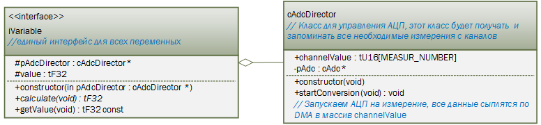
And then I painted what the temperature might look like:
And after that it was thought that it would be good to have a filter for smoothing the results of measurements. And since the filter is needed by all variables, it can be done in the form of an interface. As a result, this concept was created:
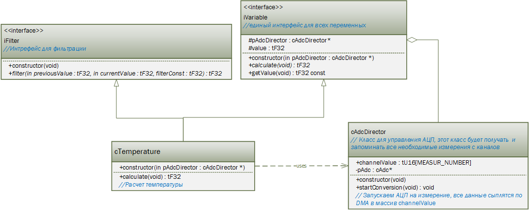
The temperature class implements the interface calculation method. But here you should make a remark, for calculating the temperature, factory coefficients are used that are wired in the microcontroller, and in theory, in order to port this code to another platform, you would need to make a class to access non-volatile parameters and pass the reference to this class to the classes that need these coefficients. in this case the temperature. But I just didn’t want to have enough time to spare a city-side because of the three coefficients, so we’ll write this down on the lack of time and leave a tick in my mind that the porting will not work here (well, okay :)). The implementation of this whole thing looks like this:
ivariable.h
#include "types.h" // #include "adcdirector.h" // cAdcdirector class iVariable { public: explicit iVariable(const cAdcDirector *pAdcDirector); virtual tF32 calculate(void) = 0; tF32 getValue(void) const {return value;}; protected: const cAdcDirector *pAdcDirector; tF32 value; }; ivariable.cpp
#include "ivariable.h" // #include "susuassert.h" // for ASSERT /******************************************************************************* * Function: constructor * Description: ******************************************************************************/ iVariable::iVariable(const cAdcDirector *pAdcDirector) { ASSERT(pAdcDirector != NULL); this->pAdcDirector = pAdcDirector; this->value = 0.0F; } temperature.h
#include "types.h" // #include "adcdirector.h" // cAdcdirector #include "ifilter.h" // iFilter #include "iVariable.h" // iVariable class cTemperature : public iVariable, private iFilter { public: explicit cTemperature(cAdcDirector *pAdcDirector); tF32 calculate(void); }; temperature.cpp
#include "temperature.h" // // 110 - 30 ( ), 289 #define DELTA_110_30 80.0F // , 28 , 30 :) #define DEGREE_30 28.0F // 2 102 CD00277537.pdf #define TS_CAL2_ADDR 0x1FF8007C // 1 102 CD00277537.pdf #define TS_CAL1_ADDR 0x1FF8007A // VDDA 3.0 #define VDDA_CAL_ADDR 0x1FF80076 #define FILTER_CONST 20.0F /******************************************************************************* * Function: constructor * Description: ******************************************************************************/ cTemperature::cTemperature(cAdcDirector *pAdcDirector) : iVariable(pAdcDirector) { } /******************************************************************************* * Function: calculate * Description: ******************************************************************************/ tF32 cTemperature::calculate(void) { tF32 temperature = 0.0F; // tF32 vdda = 0.0F; // vdda // , 289 CD00240193.pdf // 102 CD00277537.pdf tF32 tsCal2 = (tF32)(*((tU32 *)(TS_CAL2_ADDR)) >> 16); tF32 tsCal1 = (tF32) (*((tU32 *)(TS_CAL1_ADDR ))); tF32 vddaCal = (tF32)(*((tU32 *)(VDDA_CAL_ADDR)) >> 16); temperature = (tF32)this->pAdcDirector->channelValue[SENSORTEMPERATURE_CHANNEL]; vdda = (tF32)this->pAdcDirector->channelValue[VDDA_CHANNEL]; // 3.0 VDDA, // vdda, // 289 CD00240193.pdf temperature = DELTA_110_30 * ((temperature * vddaCal)/vdda - tsCal1) / (tsCal2 - tsCal1) + DEGREE_30; this->value = this->filter(this->value, temperature, FILTER_CONST); return this->value; } The same focus is repeated with the variables Vdda and Trimmer (variable resistor). The architecture is identical to the cTemeture class architecture.
Well, the main requirement of the project has been implemented, I must admit, I was busy with it for longer than planned - almost 7 days. But this is more because of the misunderstanding with the voltage of the variable resistor, stupid for a very long time, why nothing is measured. Well, I thought of looking at the Olimex board developers :) There was one small task left - outputting to the indicator. I thought that there would be nothing complicated, since my last project of 8 years ago was just on the PIC16 with a built-in indicator driver, and the indicator will be given to me very simply. And how it happened, I will tell in the final part.
Source: https://habr.com/ru/post/261823/
All Articles