"Programming a mouse" for microcontrollers
Many microcontroller platforms support tools for creating initial configuration of peripheral devices and I / O ports. Typically, this is a graphical environment in which the parameters of the crystal are set and the source code can be generated - the blank of the future project.
When using such a configurator, you significantly simplify the initial stage of programming, but do it not to the detriment of understanding the processes occurring on the chip.
Below is an example of using a configurator for a C8051F930 microcontroller from Silicon Labs. We will control the brightness of the LED with a potentiometer, writing with your hands just two lines of code. Just for fun, of course.

All Silicon Labs software development tools are available as part of the Simplicity Studio software platform. The platform is distributed free of charge and contains IDE, documentation, a lot of examples of programs, as well as additional utilities like the power consumption profiler and the configurator. In this example, the configurator and development environment will be used.
The debugging board C8051F930-TB serves as a hardware platform, since it has a potentiometer and an LED, and the C8051F930 microcontroller has the necessary ADC and PWM blocks. In general, a simple set of requirements is imposed on the board, which is suitable for a variety of debugging tools. But the C8051F930-TB was on hand :)
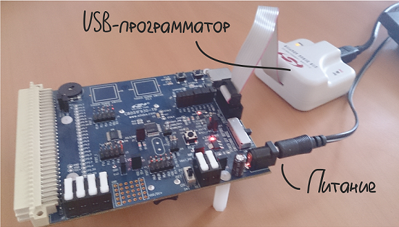
Preparation is to install and run Simplicity Studio on a computer and turn on the debug board. The board is powered from the battery or from the network and, in the absence of the built-in debugger, is connected to the computer via the DEBUGADPTR1-USB programmer.
')
After the correct connection, the board is detected by the medium, and all tools for 8-bit crystals become available.
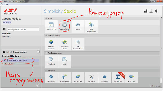
For the well-known debug board, the dialog for creating a new project appears immediately after clicking on the configurator icon. The project creation wizard does not contain any unusual elements, only the selection of the target controller, the name and location of the project, etc.
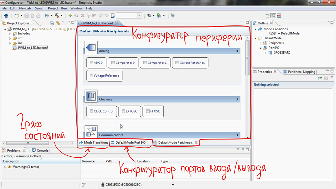
The interface of the configurator itself consists of three main parts:
The peripheral device configurator is a list of peripheral modules and core functions available on the selected chip. For the implemented task you will need:
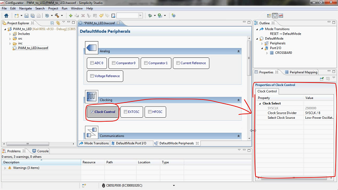
But let's start with the inclusion of the controller clock generator. It is enough to tick Clock Conrol - the built-in 25 MHz frequency generator with a divider by 8 suits us perfectly, therefore we leave the block settings available in the window on the right with the default settings.
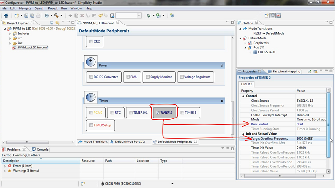
After setting the clock, go to the timers-counters. We will poll the ADC once in 1 ms, so we set TIMER2 to overflow with the appropriate frequency: put a tick on the TIMER2 block, specify the frequency in microseconds, set the Start in the Run Control field so that the timer starts automatically.
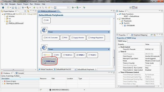
When TIMER2 was activated, the Timer Setup module turned on in red. Timer Setup must be activated for timers / counters, tick.
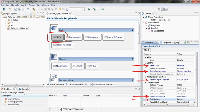
By overflowing the timer, the conversion will begin on the ADC block. Configuring the ADC includes enabling the operation of the block, specifying the event for starting the operation, specifying the I / O line for receiving the measured signal, and selecting the 8-bit conversion mode without amplification.
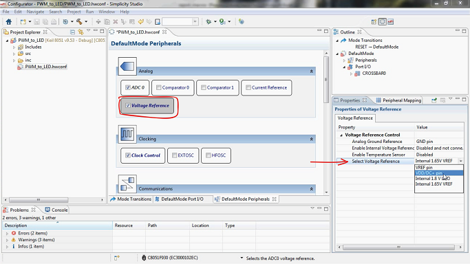
The reference voltage for the ADC is specified in a separate Voltage Reference block. In the appropriate paragraph indicate the voltage of the board.
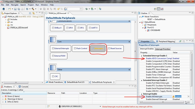
So, with the correct implementation of the described settings, we get a working crystal, in which the millisecond value in the result register of the ADC is updated in accordance with the position of the potentiometer wheel. To use this value for generating a PWM signal, it is necessary, in addition to setting the PWM block, to enable an interrupt from the ADC and set up an interrupt handler (copy the value from the result register of the ADC to the data register of the PWM block). Using the tools of the Configurator utility, you can only configure the interrupt controller: activate the Interrupts block and the interrupt from the ADC0, enable all interrupts.
It remains to configure the PCA to generate a PWM signal. Select the desired mode on Channel0 and set the automatic start (i.e. immediately after switching on or reset).
The mode of the controller is created. Go to the next tab to configure the input / output ports - you will need to determine the input of the ADC and the PWM output in accordance with the topology of the board.
The P0.6 line connected to the potentiometer was indicated as an input for the signal even when setting ADC0. It is marked on the pinout of the crystal. On the right, in the settings window of the selected “legs” mode of operation, two red crosses unambiguously hint that two parameters need to be corrected.
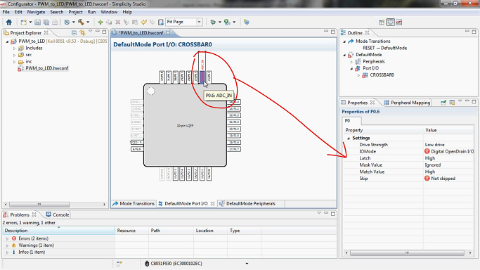
Open Drain mode is not suitable for analog input, change it to Analog I / O. The Skip parameter refers to a CROSSBAR, a digital switch that establishes “peripheral module -> input / output ports” connections in C8051Fxxx microcontrollers. Since the P0.6 line is the input of the microcontroller, it should not be taken into account in the CROSSBAR. Choose Skipped.
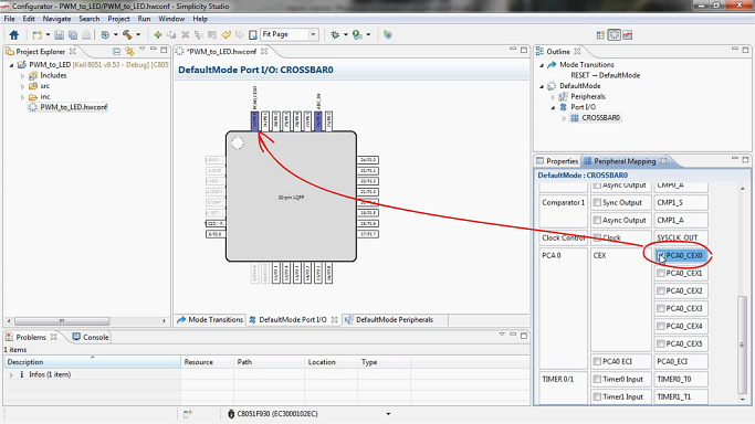
Go to setting the output for the PWM signal - the zero channel of the PCA block should be brought to the P1.6 line, to the yellow LED. Such a relationship is just given through CROSSBAR. We allow his work.
The CROSSBAR settings menu has appeared. Put a tick on the zero PCA channel, the PWM is automatically on the P0.0 line.
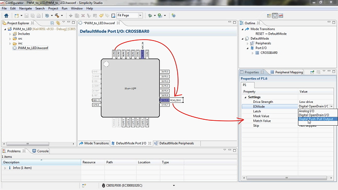
PWM should be “moved” to P1.6, and for P1.6 you should specify the mode of Push-Pull Output instead of Open Dain.
Generation and updating of the source code from the specified configuration occurs when the project is saved or by the command Generate Source, accessible from the menu by pressing the right mouse button. The source code must be supplemented with an interrupt handler, and the handler template is created automatically due to the resolution of the ADC interrupt.
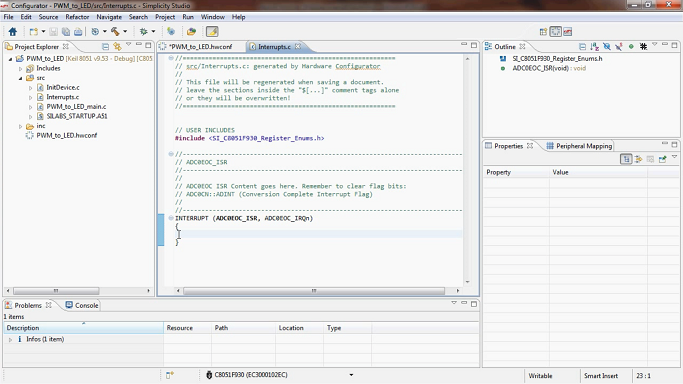
We write the very two lines of code: remove the interrupt flag at the end of the conversion, copy the contents of the ADC data register to the PWM register.
In addition to the peripherals and ports configurators, for 8-bit microcontrollers a tool is available for defining state graphs. The tools that were used above describe the default mode of the controller, and in the state column it is possible to create several modes, each of which will have its own configurator of peripherals and ports. However, in this example, the C8051F930 operates in a single mode.
The project was created, remained assembly, compilation and programming of the crystal.
The result of the work is on video.
Resource Used
When using such a configurator, you significantly simplify the initial stage of programming, but do it not to the detriment of understanding the processes occurring on the chip.
Below is an example of using a configurator for a C8051F930 microcontroller from Silicon Labs. We will control the brightness of the LED with a potentiometer, writing with your hands just two lines of code. Just for fun, of course.
Initial data
All Silicon Labs software development tools are available as part of the Simplicity Studio software platform. The platform is distributed free of charge and contains IDE, documentation, a lot of examples of programs, as well as additional utilities like the power consumption profiler and the configurator. In this example, the configurator and development environment will be used.
The debugging board C8051F930-TB serves as a hardware platform, since it has a potentiometer and an LED, and the C8051F930 microcontroller has the necessary ADC and PWM blocks. In general, a simple set of requirements is imposed on the board, which is suitable for a variety of debugging tools. But the C8051F930-TB was on hand :)
Step 1. Preparation
Preparation is to install and run Simplicity Studio on a computer and turn on the debug board. The board is powered from the battery or from the network and, in the absence of the built-in debugger, is connected to the computer via the DEBUGADPTR1-USB programmer.
')
After the correct connection, the board is detected by the medium, and all tools for 8-bit crystals become available.
Step 2. Creating a project
For the well-known debug board, the dialog for creating a new project appears immediately after clicking on the configurator icon. The project creation wizard does not contain any unusual elements, only the selection of the target controller, the name and location of the project, etc.
The interface of the configurator itself consists of three main parts:
- Peripheral Configurator
- I / O port configurator
- Microcontroller state graph
Step 3. Configuring Peripherals
The peripheral device configurator is a list of peripheral modules and core functions available on the selected chip. For the implemented task you will need:
- Activate and adjust the ADC to process the signal from the potentiometer;
- Activate and adjust the timer to initiate conversion to the ADC with the desired frequency;
- Activate and configure the PCA unit (the so-called programmable array of meters), on which a hardware PWM generator is available on the C8051Fxxx microcontrollers.
But let's start with the inclusion of the controller clock generator. It is enough to tick Clock Conrol - the built-in 25 MHz frequency generator with a divider by 8 suits us perfectly, therefore we leave the block settings available in the window on the right with the default settings.
After setting the clock, go to the timers-counters. We will poll the ADC once in 1 ms, so we set TIMER2 to overflow with the appropriate frequency: put a tick on the TIMER2 block, specify the frequency in microseconds, set the Start in the Run Control field so that the timer starts automatically.
When TIMER2 was activated, the Timer Setup module turned on in red. Timer Setup must be activated for timers / counters, tick.
By overflowing the timer, the conversion will begin on the ADC block. Configuring the ADC includes enabling the operation of the block, specifying the event for starting the operation, specifying the I / O line for receiving the measured signal, and selecting the 8-bit conversion mode without amplification.
The reference voltage for the ADC is specified in a separate Voltage Reference block. In the appropriate paragraph indicate the voltage of the board.
So, with the correct implementation of the described settings, we get a working crystal, in which the millisecond value in the result register of the ADC is updated in accordance with the position of the potentiometer wheel. To use this value for generating a PWM signal, it is necessary, in addition to setting the PWM block, to enable an interrupt from the ADC and set up an interrupt handler (copy the value from the result register of the ADC to the data register of the PWM block). Using the tools of the Configurator utility, you can only configure the interrupt controller: activate the Interrupts block and the interrupt from the ADC0, enable all interrupts.
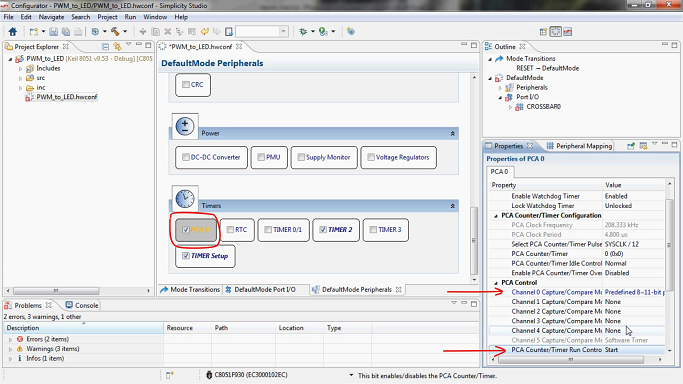
It remains to configure the PCA to generate a PWM signal. Select the desired mode on Channel0 and set the automatic start (i.e. immediately after switching on or reset).
Step 4. Configure I / O ports
The mode of the controller is created. Go to the next tab to configure the input / output ports - you will need to determine the input of the ADC and the PWM output in accordance with the topology of the board.
The P0.6 line connected to the potentiometer was indicated as an input for the signal even when setting ADC0. It is marked on the pinout of the crystal. On the right, in the settings window of the selected “legs” mode of operation, two red crosses unambiguously hint that two parameters need to be corrected.
Open Drain mode is not suitable for analog input, change it to Analog I / O. The Skip parameter refers to a CROSSBAR, a digital switch that establishes “peripheral module -> input / output ports” connections in C8051Fxxx microcontrollers. Since the P0.6 line is the input of the microcontroller, it should not be taken into account in the CROSSBAR. Choose Skipped.
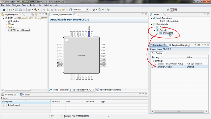
Go to setting the output for the PWM signal - the zero channel of the PCA block should be brought to the P1.6 line, to the yellow LED. Such a relationship is just given through CROSSBAR. We allow his work.
The CROSSBAR settings menu has appeared. Put a tick on the zero PCA channel, the PWM is automatically on the P0.0 line.
PWM should be “moved” to P1.6, and for P1.6 you should specify the mode of Push-Pull Output instead of Open Dain.
Step 5. Generation and addition of source code
Generation and updating of the source code from the specified configuration occurs when the project is saved or by the command Generate Source, accessible from the menu by pressing the right mouse button. The source code must be supplemented with an interrupt handler, and the handler template is created automatically due to the resolution of the ADC interrupt.
We write the very two lines of code: remove the interrupt flag at the end of the conversion, copy the contents of the ADC data register to the PWM register.
ADC0CN_ADINT = 0; PCA0CPH0 = (U8) (ADC0 >> 2); In addition to the peripherals and ports configurators, for 8-bit microcontrollers a tool is available for defining state graphs. The tools that were used above describe the default mode of the controller, and in the state column it is possible to create several modes, each of which will have its own configurator of peripherals and ports. However, in this example, the C8051F930 operates in a single mode.
Step 6. Compile, run
The project was created, remained assembly, compilation and programming of the crystal.
The result of the work is on video.
Resource Used
Source: https://habr.com/ru/post/261253/
All Articles