STC Metrotek: how it was. Part One (2004-2006)
Introduction
At the insistent request of Des333 (why everyone writes, and you don’t?), Publish the story of STC Metrotek.
Not so long ago in St. Petersburg there was such an institute - LONIIS (Leningrad branch research institute of communication), in which they developed various useful and useless things related to communication. In particular, the full analogue of the Finnish digital telephone exchange DX-200 was created there, but this analogue was called ATTS-90 on domestic components. Who then knew that our electronics is waiting? In addition, in the nineties, research institutes actively engaged in certification of foreign equipment: from telephones to office PBXs, which brought a good income and made it possible to develop other areas. For example, measuring and testing communication channels and signaling protocols in telephony. Access to both Russian and international standards was organized, it was possible to purchase any software and development tools. In addition, the experience of creating a digital telephone station made it possible to make their equipment of any complexity. In general, it was cool. Almost exactly the same as that of the Strugatskys on Monday begins on Saturday.
Now LONIIS no longer exists, but there is the Leningrad branch of the Central Research Institute of Communication, that is, LO ZNIIS. At the beginning of the "zero" one director was replaced by another, the war began, and the dawn, as always happens, was replaced by sunset.
The beginning and the first pancake
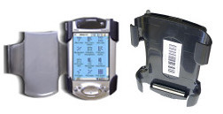
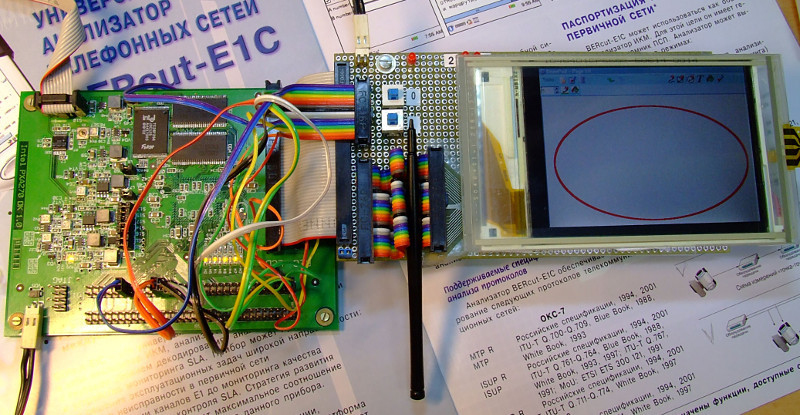
Four engineers, confident in their abilities and knowledge, decided to organize their company for the development and production of measuring equipment for telecommunications. Found partners, money, registered a legal entity, removed the so-called office space, repaired it and began to produce a new super-device for analyzing the alarm system OKS-7 and DSS1 based on a handheld from Compaq iPAQ 3950 . Here is this:
This is a four-port analyzer for the OKS-7 signaling protocols and DSS1 / PRI. I will omit the development details, but I will say that at that time (2004) it was a rather bold decision (
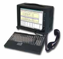
Quite a big box with ISA-boards that are connected to the PCM / E1 paths under test. And our device fits easily in your pocket. However, this turned out to be one of the factors that played a fatal role in his fate. Firstly, it was difficult for customers to imagine that a device ten times smaller in size could perform the same functions as a hefty computer. Secondly, we were told in plain text: “What are you guys? His sprint on the second day of use! ”Another natural reason for the failure was that handheld computers lost the battle for the user and the manufacturers took them out of production. And what was the iPAQ's convenient 100-pin connector for connecting external devices!
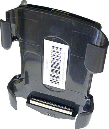
In the picture above - the so-called sleeve with the interface board and the analyzer that we developed inside. Used body from CompactFlash-expansion. Then you could easily order any parts on Foxconn. However, in spite of everything, about 30 devices managed to be quite successfully attached.
')
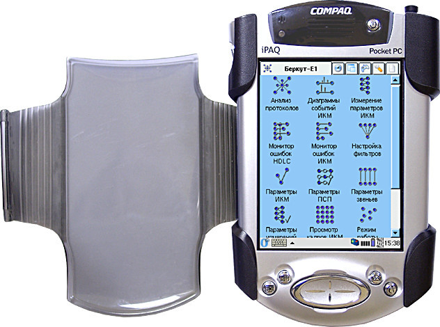
Testing E1
Admittedly, in 2005 we knew little about testing PCM, but since the transmission medium for signaling, which we were able to analyze, was the E1 paths, we decided to make an inexpensive analyzer for their (paths) measurements. Thus, a 2048 kbps Bercut-E1 analyzer was born. In the process of development, our programmers learned a lot of new and interesting, the standards were studied along and across, the rake race was more than fascinating. The error in the choice of the ADC bandwidth to obtain the pulse shape made it possible to master the methods of analyzing the physical signal using a stroboscope; insufficiently careful reading of the processor documentation helped to subsequently deal with the brownout mechanism of the detector , as well as with the hysteresis effect, as a result of which this mechanism did not work; The 320x240 display controller was written on fpga ... Yes, there was a lot of things! And it was great.
Here is a piece of ChangeLog
2004/08/20 * video.c: . [fam] 2004/08/19 + mem.c: + video.c: . . * service.c: epcs fpga epcs_nconf_clr() epcs_nce_set() [fam] 2004/08/18 * epcs.c: epcs flash' [fam] * fpga.c: fpga epcs [fam] 2004/08/17 * xmodem.c: usart0 xmodem [fam] * service.c: DataFlash, flash' [fam] 2004/08/12 + init.c: * timer?.?: * flash.c: ! DataFlash. [fam] * defines.h: , . defines : DDR_XX -- data direction register XX (DDRB) DD_XX -- DDR (DDB1) PORT_XX -- (PORTB, ) IPORT -- input (PINB) XX - , (PB1) PIN_XX -- input (PINB1) [fam] 2004/08/11 * , spi . . . [fam] 2004/08/10 Anyway, we released the device in mass production, even made a little for export, and it also became the de facto standard for PCM measurements in domestic telephony. Apparently, it was possible to still catch luck by the tail on the decline of the wave. And it gave us the opportunity to move on.
Making your handheld
In the meantime, as I said, the handhelds were removed from production and we decided that it would not be very difficult to do something similar on our own. No sooner said than done. And the development of the device based on the Intel PXA270 processor began. He didn’t have enough of his own strength, so they attracted Timur Tashpulatov, who kindly agreed to help with the circuitry and layout of the board, despite the fact that he hadn’t been engaged in such things before. The result is this:
The exhibit in the company's museum, with Linux insider, is the same Opie , which we installed on the iPAQ, aka “Bercut-C”, fixed by the jambs in the bootloader and the qt-application as an example of output to the screen. Oddly enough, it all worked almost the first time. The most difficult thing was probably to get the jtag interface working properly.
And then we developed a new board, which was installed in a solid metal case. The design of the case was modeled in Blender's 3-d editor for a couple of nights, and then buyers began to say: “We want this device, fashionable, with a wave”.
Actually, it looked like this:
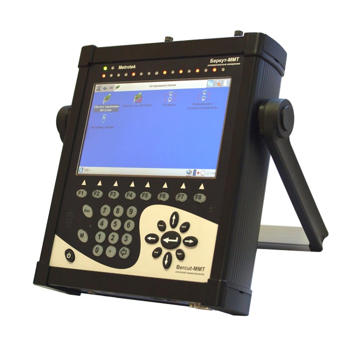
Here you can read about the device in a little more detail. The fact that it is modular, with a large screen, with a large battery capacity. But something about what you link will not know. About what is inside and what is good, and what is bad from the standpoint of the developer of the device. Because now, looking back, you can safely talk about what we have done well and what not, what absolutely could not be done, why reinvent the wheel and what tasks needed to be solved differently. But about this, I hope, I will write next time.
Thank you for reading this part of the story to the end.
Source: https://habr.com/ru/post/260979/
All Articles