Acquaintance with the robotic constructor TRIK: reverse pendulum
Introduction and formulation of the problem

What do female breasts and toy railroad have in common? That's right, and that, and that is intended for children, and dads play with them. A few days ago I got a TRIK robotics designer. The kit is quite harsh, the developers claim that it is good for rapid prototyping and for training, namely (self-) learning I am currently interested in.
What is now widely available on the market for robotic games? Self-made production of boards for each project is not considered. Lego, crucify, arduino. Lego is beautiful, but unfortunately very, very limited. Crucify and Arduins are expanding quite well, but they are rather inconvenient and quickly turn into scattering of different nameplates. This is where St. Petersburg guys go to the market with their designer TRIK.
')
So, my task is to understand how it is available to the general public (me). I have never attended lectures on theoretical cybernetics or control theory. Ohm's law, I learned just enough to understand that the socket is not worth licking, and the soldering iron is not my friend. But like any normal (overgrown) child, I love to play, and therefore I became interested in this topic.
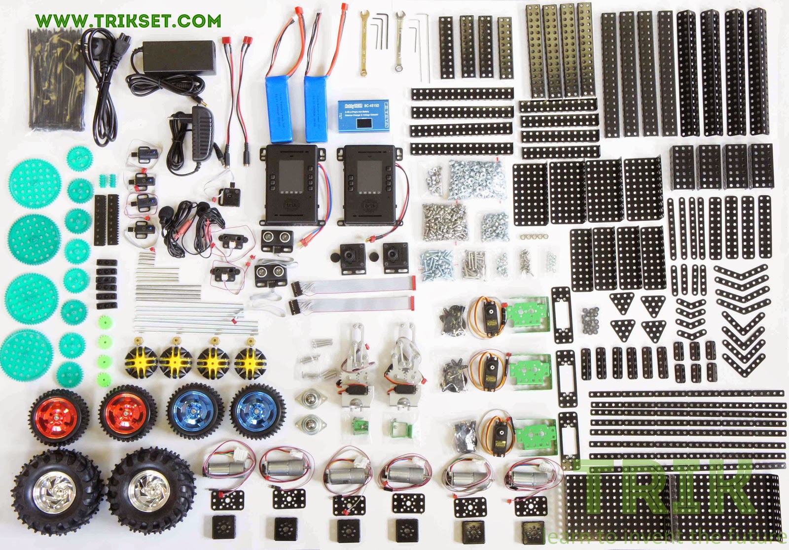
I got this set:
In general, the price of their sets varies from about twenty to seventy thousand rubles. Is it more expensive than Lego? Not. A month ago, I bought a Lego EV3. The price of the issue is € 370 base set + € 100 battery (are they absolutely fucked up there ?!) And I didn’t even consider the charger for thirty euros. Plus, neither the sonar (+ 35 €) nor the gyroscope (+ 35 €) are included in the basic set. And we can forget about the camera with a microphone in general, without mentioning in general, in principle, the lack of access to the inside of Legovsky Linux.
My set (it was laid out in the previous photo) includes two controllers , two cameras, two microphones, sonars, two types of infrared sensors, buttons, six electric motors with optoencoders, three servos, two mechanical captures, a bunch of wheels, including holonomic ones, charging-battery-laces, cog wheels, slats and a bunch of metal plates and corners (hello childhood!). The constructor is purely for a start, in general, almost everything that is enough imagination can be connected to the controller. ARM9 central processor, under the video a separate processor, so as not to load the central one. You can program on anything from assembly to C #, you are given a root console, plus the entire firmware code is open source.
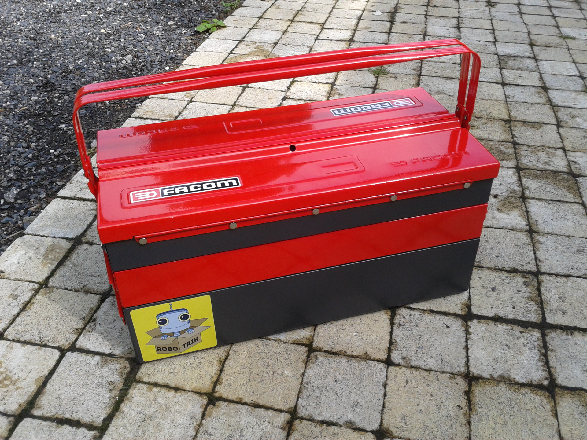
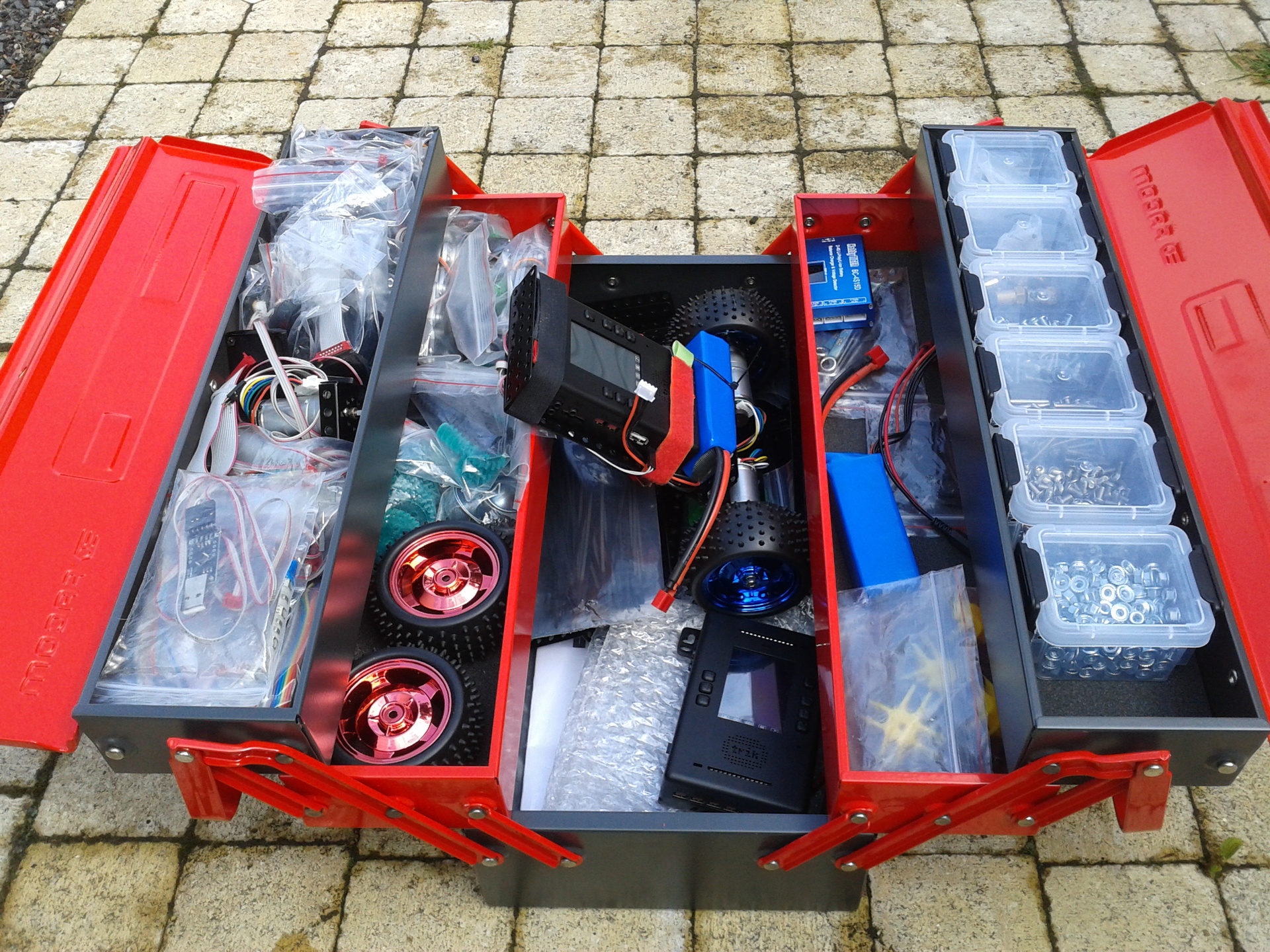
This is what my wonder box looks like:
As the very first project I decided to assemble a reverse pendulum, it is presented in the title picture. This is how it looks from behind:
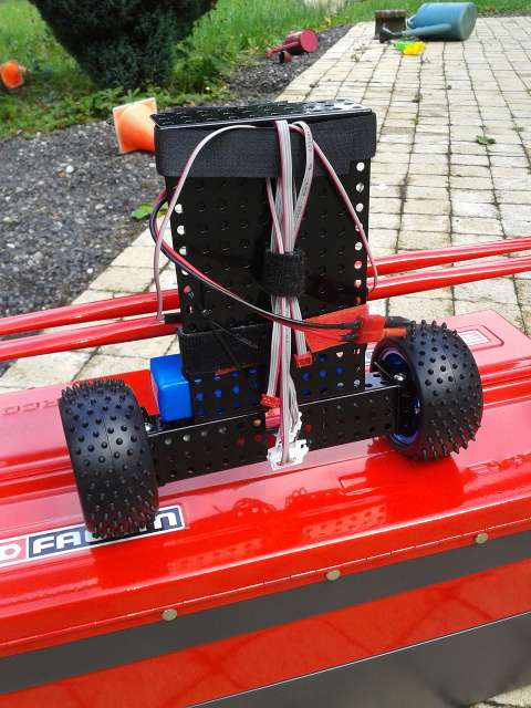
From the kit I needed two engines, two wheels, a bit of fasteners and a controller with a battery directly. My goal was not to copy the tutorial from the TRIK training course, I’m interested to break off teeth about all the problems on my own, so I’ll reinvent the wheel.
So, I have at my disposal one degree of freedom, an accelerometer and a gyroscope; I did not use encoders from engines. I will write on Qt Script.
Reading sensors
Initially, I wanted to do with an accelerometer. Like, I read the sign of the projection on the Z axis, if it is positive, then I twist the wheels in one direction, if negative, then in the other. In theory, everything is fine, but having done this, I achieved only the wild jerking of my cart. He sighed and sat down to study the literature, the good that it was not very long. So, I am only interested in the angle of deviation of the trolley from the vertical.
Gyroscope
It is the angular velocity sensor, gives a good smooth signal, but in order to track the orientation in space with its help, the speed needs to be integrated. Initially, the speeds are issued with an error, the integration introduces more errors, which ultimately will lead to the disappearance of the gyroscope readings. Therefore, only a gyroscope is not enough for a pendulum for us, we need to combine it with an accelerometer.
Here is my code for working with a gyroscope, here while (true) is the main program loop.
var gyr_x_angle = 0; var lasttime = Date.now(); while (true) { var G = brick.gyroscope().read(); G[0] = G[0] + 69; // drift correction var curtime = Date.now(); var dt = (curtime - lasttime)/1000.0; lasttime = curtime; gyr_x_rate = G[0] * 0.07; gyr_x_angle = gyr_x_angle + gyr_x_rate * dt; } In the array G, I read the sensor values, in the next line I correct the axis of interest to me. It turns out that my particular sensor at full speed shows an average speed of 69 units, so I subtract them to get the speed of interest to me.
The sensor gives an integer that you want to translate into corners. In normal mode, it works at 2000 degrees / sec (dps). Datashit says this corresponds to a constant at 70mdps / digit. Thus, G (digits) * 0.07 (dps / digit) gives us the angular velocity. It remains to integrate it by multiplying by the measurement time dt.
Accelerometer
From the accelerometer, the angle is even simpler to obtain, but the problem is that it is painfully noisy, and when the cart starts to twitch back and forth, light out at all. Here is the code:
[...] while (true) { [...] var A = brick.accelerometer().read(); var a_x_angle = Math.atan(A[2] / A[0]) * 180.0 / pi; } Extinguish noise: the combination of accelerometer and gyroscope readings
[...] var CF_x_angle = 0; while (true) { [...] CF_x_angle = 0.98*(CF_x_angle+ gyr_x_rate*dt) + 0.02*a_x_angle; } It simply says that the value of the current angle is 98% the value of the previous angle corrected from the gyroscope, and 2% is the direct reading of the angle from the accelerometer. This combination allows you to deal with floating gyro, note that we did not use the gyr_x_angle variable here.
PID controller
As I said, I did not attend smart lectures on control theory, so LQR regulators are too tough for a reasonable (couple of hours) time. But the PID is fine.
Code
In the previous paragraph, we obtained a decent (I hope) estimate of the angle of deviation of the trolley from the vertical. You can improve it using Kalman filtering, but this is shooting from a cannon at the sparrows. Now it's time to turn the wheels - the greater the angle of deflection, the faster you need to turn the wheel.
The speed of rotation of the wheel, which will give us the PID, consists of three (weighted) terms: proportional, integrating and differentiating. Proportional is simply equal to the angle of deviation from the vertical, the integrating is the sum of all regulation errors, and the differentiator is proportional to the rate of change of the deviation from the vertical.
It sounds scary, but in fact the code is extremely simple:
full program code
var gyr_x_angle = 0; var lasttime = Date.now(); var CF_x_angle = 0; var iTerm = 0; var CF_x_angle_prev = 0; var KP = 0; var KI = 0; var KD = 0; while (true) { var G = brick.gyroscope().read(); G[0] = G[0] + 69; // drift correction var curtime = Date.now(); var dt = (curtime - lasttime)/1000.0; lasttime = curtime; gyr_x_rate = G[0] * 0.07; var A = brick.accelerometer().read(); var a_x_angle = Math.atan(A[2] / A[0]) * 180.0 / pi; CF_x_angle = 0.98*(CF_x_angle+ gyr_x_rate*dt) + 0.02*a_x_angle; // ! var pTerm = KP*CF_x_angle; // iTerm = iTerm + KI*CF_x_angle; // var dTerm = KD * (CF_x_angle - CF_x_angle_prev); // CF_x_angle_prev = CF_x_angle; power = pTerm + iTerm + dTerm; brick.motor(M3).setPower(power); brick.motor(M4).setPower(power); } Choice of constants KP, KI, KD
The most difficult part remains: to find the weights in total, unfortunately, this can only be done empirically.
First we find the coefficient KP. We set KI and KD equal to zero and increase KP starting from zero until the moment when our cart starts to make (approximately) constant oscillations, like this (KP = 8, KI = 0, KD = 0):
Obviously, this is a brute force, the trolley receives a too strong signal from the proportional component, so reduce it by about half, we get this (KP = 5, KI = 0, KD = 0):
Now the cart lacks a purely proportional signal, we increase its speed by adding an integrating component. Smoothly increasing KI from scratch, trying to reach the moment when we again get the trolley oscillations around the desired position (KP = 5, KI = 0.5, KD = 0):
Now we add a differentiating component that will play the role of a damper, quenching the oscillations, this is what I get (KP = 5, KI = 0.5, KD = 5):
Conclusion
I pretty quickly (in one evening) turned out self-balancing trolley. Considering that the program turned out to be as much as twenty-five lines, now, at leisure, it remains to add control of the cart, turns and passing of the obstacle course, this should not be a big deal.
I have neither electrical, nor cybernetic background, that is, it is quite accessible to ordinary users, which, actually, is very interesting to me. I will continue to study!
Compared with the same Leg set, it all, of course, looks a bit more clumsy, the Chinese sensors (like the Lego), but not rolled up into thick high-quality Legovsky plastic. Less licked software that is in active development. The community of people programming on this controller is much smaller, but considering that a project without a year is a week, and even seeing the recent success of the Arduino, this frightens me a little. But I admire the flexibility of the controller, which was obtained from the amazing enthusiasm with which in St. Petersburg they took up the development.
Update: controller specifications
Many do not understand the difference between the Tricov controller and the Arduino or the Legovian boxes. Therefore, here is a sign:
| Central Processing Unit (CPU) | OMAP-L138 C6-Integra ™ DSP + ARM® SoC, Texas Instruments |
| CPU clock speed | 375 MHz |
| CPU core | ARM926EJ-S ™ RISC MPU |
| DSP core CPU | C674x Fixed / Floating-Point VLIW DSP |
| RAM | 256 MB |
| FLASH - memory | 16 MB |
| Peripheral Processor (PP) | MSP430F5510, Texas Instruments |
| Clock frequency PP | 24 MHz |
| User interfaces | USB 2.0, WiFi b / g / n, BlueTooth, 2 * UART, 2 * I2C, Micro-SD, Mic in (stereo), Line out (mono) |
| DC motor interfaces | 4 ports of 6-12V DC motors, with individual hardware overcurrent protection (up to 2A per motor) |
| Peripheral Interfaces | 19 signal ports of general purpose (6 single-channel and 13 dual-channel) with 3.3-5V power supply, 6 of them can operate in the analog input mode |
| Video Sensor Interfaces | 2 inputs BT.656 VGA 640 * 480, support stereo mode |
| Built-in LCD monitor | 2.4 ”TFT, color, touch, resolution 320 * 240 pixels |
| Built-in speaker | Rated power 1W, peak 3W |
| Led indicator | 2-color, program-controlled |
| Expansion slots | 2 * 26-pin slotted expansion module connectors |
| Additional equipment (included in the controller) | 3-axis accelerometer, 3-axis gyroscope, audio codec, amplifier, converters and power control circuits, protection circuits for inputs against overload voltage and current |
| Power supply | 6-12V DC, external power adapter or LiPo battery RC 3P (11,1V) / 2P (7,4V) |
| Housing dimensions | 125 * 80 * 25 mm |
Source: https://habr.com/ru/post/260783/
All Articles