My little relays: Autowatering is magic
Today we will program the SDEPROM controller of an automated irrigation system for a vegetable garden.
Given:
A well with a pump, a pipe system with solenoid valves and watering nozzles, installed in ten different areas of the garden.
Required:
Ensure the sequential start of irrigation of each zone for a predetermined period of time from 5 to 30 minutes. The sequence is required due to the fact that the well cannot provide the necessary pressure on two zones at once. Provide for the possibility of using an external control unit in order to be able to include a timer, take into account soil moisture, etc.
Rolling in you will find megabytes of meat, as well as the process of the slowest firmware controller. This is not a program for you to program a bitbang!
It all started with the fact that one morning a phone call rang out, and already the next evening almost half a ton of “new” Soviet relays lay in the garage in my own boxes, saved by me from a landfill. Unnecessary dismantled, something went into other hands. With the remaining couple of hundred kilograms it was necessary to do something :)
This project has a little unloaded shelves of my cabinets. The only thing I had to buy was 15 meters of thin stranded wire, and then most of the connections took 6 sets of wires from computer power supplies. The whole project took about a month. The active assembly phase is three days.
')
First of all, let's take inventory of relays and decide which ones we will use:

We have a 10-channel system, we assume that one relay will be responsible for turning on the channel, one more for disconnecting, and on the third we will implement various locks and controls.
The first two relays - the relay of the maximum and minimum voltage PH-53 and PH-54, for a different nominal response voltage - what it was. These relays have one normally open and one normally closed contact. Need to meet.
The third relay is RPU-1. 6 NO and 2 NC contacts. Should be enough.
Some of these relays are set aside for general control.
We make night outline of the scheme:

According to the priority principle, we block the next channel by the previous one, by ensuring consistency. those. until channel 1 finishes, channel 2 will not start. Do not forget to enable sequential locking, so that skipping one of the channels does not violate this logic.
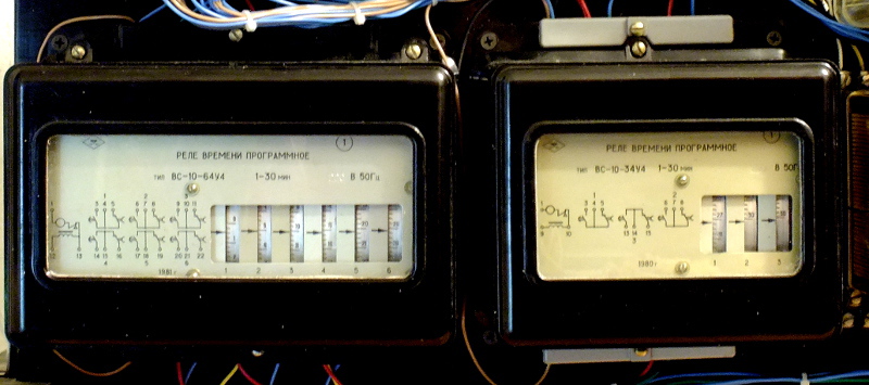
The time setting is determined by the choice of one of the channels of the programmable time relay.

Since I have a switch for 7, we use 7 time relay drums, one drum will take us to protection in time, cutting down the channel when the time reaches more than the maximum. You never know, the switch junk. one more drum will go to block the start of the next channel until the time relay is reset - it takes about a second for the drum to return to the starting point of reference.
The task of the console is to allow launching any channel, launching the necessary channels for sequential execution, resetting the current channel, resetting the entire system. Still have the ability to external control.
The console will be assembled in the case of the D-3M protective automatics relay, having previously removed the guts from there - although there are relays that we need to multiply the signals, they are too large and the new filling will not fit.
Set the buttons and switches

And mount the insides:

Relays are needed for a common start button. If a channel is selected using the toggle switch, then when you press the common power button, the channel will turn on. The relays turned out to be DC at 110V, so they are mounted two in series and fed through a diode bridge. I do not remember where I took them. Connectors for 14 pins taken from voltmeters - recorders H392. There is little confusion from the latter, but the components and the case will be very useful. Of them were taken and tumblers.
Pinout:
1 - 10 - launch channels
11 - external control of the channels, the closure of the 220V-line includes a self-blocking and time-dependent circuits.
12 - stop signal.
13 - 220V - neutral (right on the diagrams)
14 - 220V - line (left on the diagrams)
The control unit is ready. On top of the installed connector type mother, similar to the bottom pinout. It can connect an external unit.

The LEDs are not connected - their application seemed to me not to fit the device, so for now just for beauty.
Joke. I walked somehow on the porch. I look - the piano is worth it. Well, I took it and took it.
Actually, the bottom panel with its size perfectly fit as the basis for the future controller. The legs, by the way, also came in handy - during the assembly they securely held the entire structure in an upright position.
Since my RN-53 rear connection, we make cuts, so that later it was convenient to do the installation:

Install all the rear relay and control panel:
And flashing the logic of inclusion:

The first switch-on - everything works, except for one relay in the remote control - buzzes but does not work. sticky from long storage. Blow on the console and it all worked as it should. We reset, disable, and fill the free space.
While mounted the third row of the relay noticed a bug in the circuit. I fixed the bug and went to bed at three in the morning.
In the morning I fixed the bug fix ...

The moment where this bandura lies flat and from under it stick my legs into the frame did not get. It's a pity.
Set the switches. They are screw, on 7 positions, from the relay RT-81. Since they are metal open type, we connect this circuit through a 24V transformer so that it is safe to grasp with bare hands. In the diagram above, he, in a fit of night illumination, is painted black. The base block of the RF8300 relay is used as such a transformer. There is also a 24V relay.

Connect the remnants, set the time relay and set their settings.
Run again, change traffic jams and remove a couple more bugs. Works!
As a result, we have a Programmable logic controller with the following characteristics:
Now the controller does not have enough indication of the operation of the channels - the LEDs are installed, but I found them not canonical and did not connect yet. There are indicator flag relays, but they are fixed, i.e. not suitable for this case.
Even in the controller there is no terminal block for connecting the solenoid valves. I will add it later when I finish designing the cable line to them.
At the moment, during testing, a couple of bugs were found, which I will gradually correct and, having assembled an expansion module for the daily setting and humidity, so that it gives an activation signal at a certain time of day if the soil is not damp enough, next year I will put it into operation. Honestly, I have not even laid a pipe in the garden for watering.
The actual scheme is made in DipTrace and is present on GitHub: github.com/radiolok/releyirrigation
Made to it all the structural changes made during installation.
Well, the last question - in light of the existence of a huge number of industrial automation on the PLC, programs for which are compiled in the same ladder diagrams, does the community have a need for training materials on relay-contactor logic? Both discrete, and as a part of PLC.
Given:
A well with a pump, a pipe system with solenoid valves and watering nozzles, installed in ten different areas of the garden.
Required:
Ensure the sequential start of irrigation of each zone for a predetermined period of time from 5 to 30 minutes. The sequence is required due to the fact that the well cannot provide the necessary pressure on two zones at once. Provide for the possibility of using an external control unit in order to be able to include a timer, take into account soil moisture, etc.
Rolling in you will find megabytes of meat, as well as the process of the slowest firmware controller. This is not a program for you to program a bitbang!
It all started with the fact that one morning a phone call rang out, and already the next evening almost half a ton of “new” Soviet relays lay in the garage in my own boxes, saved by me from a landfill. Unnecessary dismantled, something went into other hands. With the remaining couple of hundred kilograms it was necessary to do something :)
This project has a little unloaded shelves of my cabinets. The only thing I had to buy was 15 meters of thin stranded wire, and then most of the connections took 6 sets of wires from computer power supplies. The whole project took about a month. The active assembly phase is three days.
')
First of all, let's take inventory of relays and decide which ones we will use:
We have a 10-channel system, we assume that one relay will be responsible for turning on the channel, one more for disconnecting, and on the third we will implement various locks and controls.
The first two relays - the relay of the maximum and minimum voltage PH-53 and PH-54, for a different nominal response voltage - what it was. These relays have one normally open and one normally closed contact. Need to meet.
The third relay is RPU-1. 6 NO and 2 NC contacts. Should be enough.
Some of these relays are set aside for general control.
We make night outline of the scheme:
According to the priority principle, we block the next channel by the previous one, by ensuring consistency. those. until channel 1 finishes, channel 2 will not start. Do not forget to enable sequential locking, so that skipping one of the channels does not violate this logic.
The time setting is determined by the choice of one of the channels of the programmable time relay.
Since I have a switch for 7, we use 7 time relay drums, one drum will take us to protection in time, cutting down the channel when the time reaches more than the maximum. You never know, the switch junk. one more drum will go to block the start of the next channel until the time relay is reset - it takes about a second for the drum to return to the starting point of reference.
Remote controller
The task of the console is to allow launching any channel, launching the necessary channels for sequential execution, resetting the current channel, resetting the entire system. Still have the ability to external control.
The console will be assembled in the case of the D-3M protective automatics relay, having previously removed the guts from there - although there are relays that we need to multiply the signals, they are too large and the new filling will not fit.
Set the buttons and switches
And mount the insides:
Relays are needed for a common start button. If a channel is selected using the toggle switch, then when you press the common power button, the channel will turn on. The relays turned out to be DC at 110V, so they are mounted two in series and fed through a diode bridge. I do not remember where I took them. Connectors for 14 pins taken from voltmeters - recorders H392. There is little confusion from the latter, but the components and the case will be very useful. Of them were taken and tumblers.
Pinout:
1 - 10 - launch channels
11 - external control of the channels, the closure of the 220V-line includes a self-blocking and time-dependent circuits.
12 - stop signal.
13 - 220V - neutral (right on the diagrams)
14 - 220V - line (left on the diagrams)
The control unit is ready. On top of the installed connector type mother, similar to the bottom pinout. It can connect an external unit.
The LEDs are not connected - their application seemed to me not to fit the device, so for now just for beauty.
Controller
Joke. I walked somehow on the porch. I look - the piano is worth it. Well, I took it and took it.
Musicians do not watch
By the way no joke. The piano turned out to be so-so - with a crack in the O_O futhor (knowledgeable people will understand).
Dismantled the piano while it slept ...
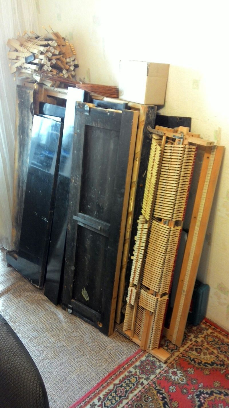
But now I have a keyboard frame and keys for the synthesizer. Someday my hands will reach him. The cast-iron frame went into scrap metal, and the cracked futor - for firewood.
Dismantled the piano while it slept ...
But now I have a keyboard frame and keys for the synthesizer. Someday my hands will reach him. The cast-iron frame went into scrap metal, and the cracked futor - for firewood.
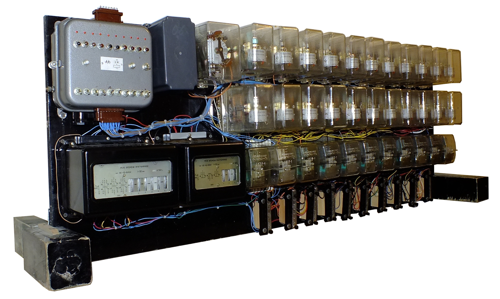
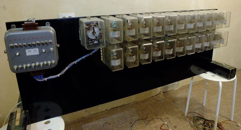
Actually, the bottom panel with its size perfectly fit as the basis for the future controller. The legs, by the way, also came in handy - during the assembly they securely held the entire structure in an upright position.
Since my RN-53 rear connection, we make cuts, so that later it was convenient to do the installation:
Install all the rear relay and control panel:
And flashing the logic of inclusion:
The first switch-on - everything works, except for one relay in the remote control - buzzes but does not work. sticky from long storage. Blow on the console and it all worked as it should. We reset, disable, and fill the free space.
While mounted the third row of the relay noticed a bug in the circuit. I fixed the bug and went to bed at three in the morning.
In the morning I fixed the bug fix ...
The moment where this bandura lies flat and from under it stick my legs into the frame did not get. It's a pity.
Set the switches. They are screw, on 7 positions, from the relay RT-81. Since they are metal open type, we connect this circuit through a 24V transformer so that it is safe to grasp with bare hands. In the diagram above, he, in a fit of night illumination, is painted black. The base block of the RF8300 relay is used as such a transformer. There is also a 24V relay.
Connect the remnants, set the time relay and set their settings.
Run again, change traffic jams and remove a couple more bugs. Works!
As a result, we have a Programmable logic controller with the following characteristics:
- The number of logical cells - 33
- Programmable Memory Type - SDEPROM (ScrewDriver Erasable Programmable Read-Only Memory)
- Two timers from 1 to 30 minutes - one for 6 channels and one for 3 channels
- One timer from 1 to 21 seconds for 2 channels.
- The maximum programming speed is 20 jumpers / hour.
- Average programming speed - 6 jumpers / hour
- The dimensions of the controller - 1333x500x200mm
- Controller weight - 45 kg
Now the controller does not have enough indication of the operation of the channels - the LEDs are installed, but I found them not canonical and did not connect yet. There are indicator flag relays, but they are fixed, i.e. not suitable for this case.
Even in the controller there is no terminal block for connecting the solenoid valves. I will add it later when I finish designing the cable line to them.
At the moment, during testing, a couple of bugs were found, which I will gradually correct and, having assembled an expansion module for the daily setting and humidity, so that it gives an activation signal at a certain time of day if the soil is not damp enough, next year I will put it into operation. Honestly, I have not even laid a pipe in the garden for watering.
The actual scheme is made in DipTrace and is present on GitHub: github.com/radiolok/releyirrigation
Made to it all the structural changes made during installation.
Well, the last question - in light of the existence of a huge number of industrial automation on the PLC, programs for which are compiled in the same ladder diagrams, does the community have a need for training materials on relay-contactor logic? Both discrete, and as a part of PLC.
Source: https://habr.com/ru/post/260643/
All Articles