Electronics for the most beginners
I try to read all the articles on Habré on electronics for beginners, DIY, Arduino. And just read the article “Arduino. 6 steps. Impressed I decided to try to throw my 5 kopecks.
The main activity is not directly related to electronics. She, like programming, has always been just a hobby. Seven years ago, I became a dad and now it's time to teach my son, at the same time to recall everything at the same time, well, and learn how to do it myself.
I return to the above article. Has anyone considered the number of uses of the word "stupid"? Stupidly take, stupidly insert, stupidly find the sketch, stupidly fill. And even if it works, we stupidly do not understand what, why, why. I am a supporter of a systematic approach. But I understand that in order to maintain interest, practice is also needed. And the first thing we learned with our son is to solder. Zero were probably endless safety instructions. And yet, the son did not escape even if he was the smallest, but the burn that rebounded when the wire was tipped off. I love him madly, I have one. But I believe that this experience was inevitable and necessary. Another of those tedious instructions was a 220 volt household electrical network. That nothing can be connected to it yourself. Explanations that you need to study for a long time. Demonstration of photographs of electric shock, endless stories "But, the boy climbed, and the current killed him. He died!!". I feel that is not right. Many will say, "You laid the complex in it, fear!". But better then I will fight with his 220-volt phobia than he will suffer, arrogantly deciding that he did everything right, and will climb to the outlet now.
Now, sitting down to solder, he puts on clothes with long sleeves, always holds the wires. Always attentive to where the soldering iron is on the table, and in what condition it is. And do not climb to the outlet. The second was the essence of the electrical circuit. What is voltage, current, resistance. Very helpful in this article on Habré. Analogies with water and pipes. Maybe great gurus and consider them inaccurate, argue. But for the child is the most. There is a battery - a pump, there are wires - pipes. There are devices that use pressure and volume of flowing water - electricity. And there are controls. Buttons, switches, switches. On the example of water, it was explained why the LED burned out. Yes, it just broke wild pressure. Of course, there were questions. If it broke, why doesn't electricity flow out? Remember, we have a shower hose broken in our bath? Inquisitive children's mind. Which as a result could understand that there are analogies. That water is an analogy, but not the same. After was practice. Infinite lanterns, lighthouses on the tower of Lego cubes, with a remote control rendered on the wire. Chain branching, main switch, single channel switches. The essence of resistance. Constriction on the pipe, nozzle, reducing the pressure. More later were electric motors, gearboxes. The first machine from the disassembled CD-Rom, which draws with a ballpoint pen, is just a straight line. But controlled with switches and buttons. A small introduction to the mechanics. What is needed gear, as it reduces speed, but increases the force.
')
And so there was a choice. What's next? Arduino? Given that he does not know how to read Russian properly. The path “We stupidly buy, we stupidly insert, we stupidly fill in the downloaded firmware”? I decided, why not be a transitional stage? Yes, chips, but so far WITHOUT arduino. Just try your hand with elementary logic. And also learn the LUT method. On the nose was the day of all lovers. And this was born:
Typical scheme, from the manual to the timer NE555. Two chips, the actual timer itself and the decimal counter - a decoder CD4017 (Russian analogue K561IE8).
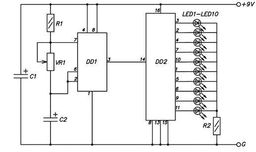
The only difference is that the decoder outputs are connected in parallel by two LEDs. Part ratings: R1 10 to 47 kΩ, VR1 (trim) 47kΩ, R2 56 ohms. C1 100µF 16V, C2 10µF 16V, 20 LEDs.
Principle of operation: C2 capacitor, R1 resistor and VR1 trimming resistor form a timed chain for the NE555 timer. The counter - decoder receives pulses from the timer and sets "one" (supply voltage) at its outputs to which the LEDs are connected. The result is a sequential inclusion of LEDs - running light. Resistor R2 limits the LED current to 10-20 mA (milliamperes). One for all, since only one output of the decoder is active at a time. Power source - battery "Krona". But the scheme will work from both the USB port and the on-board network of a motorcycle or car. It is only necessary to choose the value of the resistor R2. Both chips are very unpretentious and work quietly in the range of supply voltages from 5 to 16 volts. When powered by the “crown”, the nominal value of R1 is 10 kOhm, the timer pulse frequency is about 5 Hz, the current consumption of the entire circuit is 22 mA.
The printed circuit board is made in the shape of a heart from one-sided foiled textolyte, by laser-iron method. There is a contour line in the picture. After etching, the edges are roughly sawn with a sheet of metal, then processed with emery paper. On the manufacture of the board takes 1 hour.
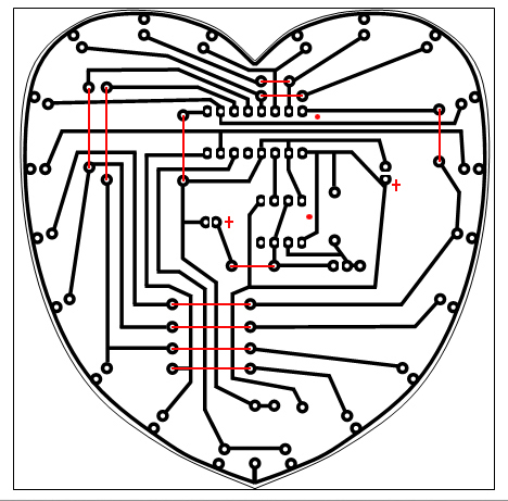
In the figure, bridges made of clipped legs of the LEDs, soldered on the part, are marked in red. Fee divorced in Word'e. Yes, I'm not friends with either Eagle or Proteus. But it's easier. Open, or print at home on a glossy photo paper on a laser printer, or in a photo workshop, copy center or mini-typography. I printed in the near center. The price of one sheet is 30 rubles. Six copies of the board pattern on the sheet.
Who is not familiar with the laser-iron method: take a piece of foil-coated textolite, clean it with a scratch, degrease with acetone or alcohol. We attach the imprint tracks toner to the foil. We iron it with a very hot iron for about five minutes, trying not to move the imprint on the foil. Put the resulting sandwich between two plywood, and press down (I have 2 dumbbells per kilogram). When cool throw in cold water. After half an hour, gently roll up the soaked paper. The entire toner, pattern, remains on the foil. Wash the paper thoroughly so that the drawing does not turn white when it dries. Especially the centers of the holes. So it will be easier to drill. If there are minor flaws (toner is not stuck everywhere) - paint on nail polish. Then we put the board in a solution of ferric chloride, swing it. In a fresh solution, the board is poisoned for 10 - 12 minutes. For hands it is safe. But you have to be careful. Ferric chloride stains are not washed from stainless steel sinks. The solution can be used repeatedly. After etching, wash the board with water, with soap and water. Wash off toner with acetone. Drill the holes with a 1 mm drill. They are pickled, the core is not necessary, the drill does not run away. Ludim or all tracks entirely, or only contact pads (in my opinion so beautiful). We give the board the desired shape with a hacksaw blade for metal and sandpaper. The fee is ready.
Prepare the details. The legs of the diodes and capacitors are pruned, leaving 2.5 - 3 mm. Bend the legs of the resistors, and also pruned. From the scraps of the legs of the LEDs do jumpers. The legs of the parts should stick out from the side of the tracks by 0.5 - 1 mm. We solder, paying attention to the polarity of the LEDs (the cathode to the common conductor along the edge), electrolytic capacitors and microcircuits (the pluses of the capacitors and the keys of the microcircuits are marked with red dots in the picture of the tracks). Soldering coped my son.
Result:
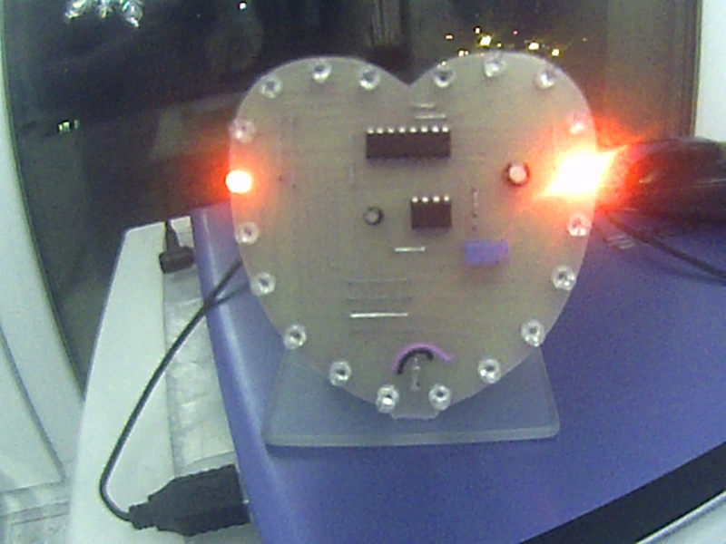
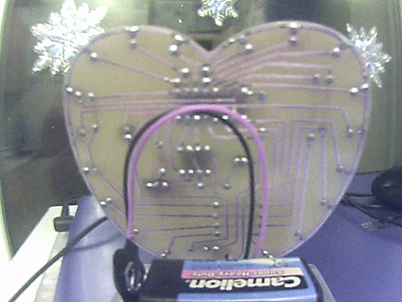
With the case we did not have time. Made only a stand made of plexiglass. A protrusion was left on the board, a groove was drilled on a Plexiglas plate. Pasted on superglue. The battery was glued behind the board on a double-sided tape.
All items can be purchased at any online store. We bought in the shops of the city. All the details, textolite sheet for 2 valentines, ferric chloride, nail polish cost us 500 rubles. And from them 300 - ferric chloride and textolite. LEDs are also expensive, 6 rubles thing. On aliexpress sold kits. The more pieces, the cheaper. Terminal for crown 25 rubles. Chips, resistors and capacitors, are generally penny (rubles).
The project can be modified. Arrange differently LEDs, greatly increase the switching time, and put the LEDs blinking in all colors randomly. Or vice versa, reduce time. The result is a heartbeat effect, a flickering red outline. You can make turn signal repeaters for mirrors auto, Moto, led. Or put under the rear window of the car as an additional brake light instead of the Chinese LED line. Just pick up the value of the current-limiting resistor R2. You can hang transistor switches at the outputs of the decoder and manage at least ten Christmas lights.
It was made 2 ready-made devices for mother and cousin. And two more boards, which remained to lie until better times. Son lost interest in this device. He already wants more. He is already dreaming of 3D printers and router machines. He knows that there are stepper motors. But the next thing we did was a bike computer. And he will already be on arduino nano. But about this in the next article.
The main activity is not directly related to electronics. She, like programming, has always been just a hobby. Seven years ago, I became a dad and now it's time to teach my son, at the same time to recall everything at the same time, well, and learn how to do it myself.
I return to the above article. Has anyone considered the number of uses of the word "stupid"? Stupidly take, stupidly insert, stupidly find the sketch, stupidly fill. And even if it works, we stupidly do not understand what, why, why. I am a supporter of a systematic approach. But I understand that in order to maintain interest, practice is also needed. And the first thing we learned with our son is to solder. Zero were probably endless safety instructions. And yet, the son did not escape even if he was the smallest, but the burn that rebounded when the wire was tipped off. I love him madly, I have one. But I believe that this experience was inevitable and necessary. Another of those tedious instructions was a 220 volt household electrical network. That nothing can be connected to it yourself. Explanations that you need to study for a long time. Demonstration of photographs of electric shock, endless stories "But, the boy climbed, and the current killed him. He died!!". I feel that is not right. Many will say, "You laid the complex in it, fear!". But better then I will fight with his 220-volt phobia than he will suffer, arrogantly deciding that he did everything right, and will climb to the outlet now.
Now, sitting down to solder, he puts on clothes with long sleeves, always holds the wires. Always attentive to where the soldering iron is on the table, and in what condition it is. And do not climb to the outlet. The second was the essence of the electrical circuit. What is voltage, current, resistance. Very helpful in this article on Habré. Analogies with water and pipes. Maybe great gurus and consider them inaccurate, argue. But for the child is the most. There is a battery - a pump, there are wires - pipes. There are devices that use pressure and volume of flowing water - electricity. And there are controls. Buttons, switches, switches. On the example of water, it was explained why the LED burned out. Yes, it just broke wild pressure. Of course, there were questions. If it broke, why doesn't electricity flow out? Remember, we have a shower hose broken in our bath? Inquisitive children's mind. Which as a result could understand that there are analogies. That water is an analogy, but not the same. After was practice. Infinite lanterns, lighthouses on the tower of Lego cubes, with a remote control rendered on the wire. Chain branching, main switch, single channel switches. The essence of resistance. Constriction on the pipe, nozzle, reducing the pressure. More later were electric motors, gearboxes. The first machine from the disassembled CD-Rom, which draws with a ballpoint pen, is just a straight line. But controlled with switches and buttons. A small introduction to the mechanics. What is needed gear, as it reduces speed, but increases the force.
')
And so there was a choice. What's next? Arduino? Given that he does not know how to read Russian properly. The path “We stupidly buy, we stupidly insert, we stupidly fill in the downloaded firmware”? I decided, why not be a transitional stage? Yes, chips, but so far WITHOUT arduino. Just try your hand with elementary logic. And also learn the LUT method. On the nose was the day of all lovers. And this was born:
Typical scheme, from the manual to the timer NE555. Two chips, the actual timer itself and the decimal counter - a decoder CD4017 (Russian analogue K561IE8).
The only difference is that the decoder outputs are connected in parallel by two LEDs. Part ratings: R1 10 to 47 kΩ, VR1 (trim) 47kΩ, R2 56 ohms. C1 100µF 16V, C2 10µF 16V, 20 LEDs.
Principle of operation: C2 capacitor, R1 resistor and VR1 trimming resistor form a timed chain for the NE555 timer. The counter - decoder receives pulses from the timer and sets "one" (supply voltage) at its outputs to which the LEDs are connected. The result is a sequential inclusion of LEDs - running light. Resistor R2 limits the LED current to 10-20 mA (milliamperes). One for all, since only one output of the decoder is active at a time. Power source - battery "Krona". But the scheme will work from both the USB port and the on-board network of a motorcycle or car. It is only necessary to choose the value of the resistor R2. Both chips are very unpretentious and work quietly in the range of supply voltages from 5 to 16 volts. When powered by the “crown”, the nominal value of R1 is 10 kOhm, the timer pulse frequency is about 5 Hz, the current consumption of the entire circuit is 22 mA.
The printed circuit board is made in the shape of a heart from one-sided foiled textolyte, by laser-iron method. There is a contour line in the picture. After etching, the edges are roughly sawn with a sheet of metal, then processed with emery paper. On the manufacture of the board takes 1 hour.
In the figure, bridges made of clipped legs of the LEDs, soldered on the part, are marked in red. Fee divorced in Word'e. Yes, I'm not friends with either Eagle or Proteus. But it's easier. Open, or print at home on a glossy photo paper on a laser printer, or in a photo workshop, copy center or mini-typography. I printed in the near center. The price of one sheet is 30 rubles. Six copies of the board pattern on the sheet.
Who is not familiar with the laser-iron method: take a piece of foil-coated textolite, clean it with a scratch, degrease with acetone or alcohol. We attach the imprint tracks toner to the foil. We iron it with a very hot iron for about five minutes, trying not to move the imprint on the foil. Put the resulting sandwich between two plywood, and press down (I have 2 dumbbells per kilogram). When cool throw in cold water. After half an hour, gently roll up the soaked paper. The entire toner, pattern, remains on the foil. Wash the paper thoroughly so that the drawing does not turn white when it dries. Especially the centers of the holes. So it will be easier to drill. If there are minor flaws (toner is not stuck everywhere) - paint on nail polish. Then we put the board in a solution of ferric chloride, swing it. In a fresh solution, the board is poisoned for 10 - 12 minutes. For hands it is safe. But you have to be careful. Ferric chloride stains are not washed from stainless steel sinks. The solution can be used repeatedly. After etching, wash the board with water, with soap and water. Wash off toner with acetone. Drill the holes with a 1 mm drill. They are pickled, the core is not necessary, the drill does not run away. Ludim or all tracks entirely, or only contact pads (in my opinion so beautiful). We give the board the desired shape with a hacksaw blade for metal and sandpaper. The fee is ready.
Prepare the details. The legs of the diodes and capacitors are pruned, leaving 2.5 - 3 mm. Bend the legs of the resistors, and also pruned. From the scraps of the legs of the LEDs do jumpers. The legs of the parts should stick out from the side of the tracks by 0.5 - 1 mm. We solder, paying attention to the polarity of the LEDs (the cathode to the common conductor along the edge), electrolytic capacitors and microcircuits (the pluses of the capacitors and the keys of the microcircuits are marked with red dots in the picture of the tracks). Soldering coped my son.
Result:
With the case we did not have time. Made only a stand made of plexiglass. A protrusion was left on the board, a groove was drilled on a Plexiglas plate. Pasted on superglue. The battery was glued behind the board on a double-sided tape.
All items can be purchased at any online store. We bought in the shops of the city. All the details, textolite sheet for 2 valentines, ferric chloride, nail polish cost us 500 rubles. And from them 300 - ferric chloride and textolite. LEDs are also expensive, 6 rubles thing. On aliexpress sold kits. The more pieces, the cheaper. Terminal for crown 25 rubles. Chips, resistors and capacitors, are generally penny (rubles).
The project can be modified. Arrange differently LEDs, greatly increase the switching time, and put the LEDs blinking in all colors randomly. Or vice versa, reduce time. The result is a heartbeat effect, a flickering red outline. You can make turn signal repeaters for mirrors auto, Moto, led. Or put under the rear window of the car as an additional brake light instead of the Chinese LED line. Just pick up the value of the current-limiting resistor R2. You can hang transistor switches at the outputs of the decoder and manage at least ten Christmas lights.
It was made 2 ready-made devices for mother and cousin. And two more boards, which remained to lie until better times. Son lost interest in this device. He already wants more. He is already dreaming of 3D printers and router machines. He knows that there are stepper motors. But the next thing we did was a bike computer. And he will already be on arduino nano. But about this in the next article.
Source: https://habr.com/ru/post/260613/
All Articles