We use the built-in microcontroller in Intel Edison
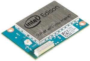 I think that many of you are already familiar with Intel Edison from the previous notes, and some, after reading the specifications, probably had a question - what is the second mysterious MCU processor running at 100 MHz? Why is it needed? How to use it?
Meanwhile, the role of the MCU in some cases is extremely important. Those who tried to use Edison to work with various sensors may have already noticed - Intel Edison does not provide a real-time response to their readings when working from Linux. And here comes the MCU. It's time to tell a little about this built-in microcontroller, its architecture, areas of application and consider a practical example.
Since 2.1, the software for Intel Edison has added the ability to use the integrated microcontroller.
Consider a system on a chip used in the Intel Edison Compute Module:

The system on a chip used in the Intel Edison Compute Module includes two processors:
- Intel Atom dual-core processor operating at 500 MHz. Designated as Host CPU.
- Microcontroller architecture Minute IA, operating at 100 MHz. Designated as MCU.
Consider the microcontroller in more detail. The Minute IA Computing Core is an energy efficient architecture based on 486 with the addition of commands for compatibility with the Pentium. In addition to the computational core, the microcontroller contains an input-output subsystem (GPIO, I2C, High Speed UART, DMA) and SRAM. The microcontroller has access to all GPIO ports in the Edison Compute Module. The total amount of SRAM for code and data is 192 kb. The microcontroller runs the Viper OS real-time operating system from WindRiver.
')
The microcontroller application runs on top of the Viper core and controls the peripherals connected to the MCU, regardless of the Intel Atom processor. For example, it can manage GPIO ports, interact with sensors using I2C or UART, and exchange data with the Intel Atom processor.
Why do I need a microcontroller in Intel Edison?
I would single out two areas where you can apply the built-in microcontroller:
- Work with I / O ports and interfaces with real-time response.
- Energy efficiency.
The Intel Atom processor and the standard Yocto Linux distribution do not allow an out-of-box implementation of applications with a real-time response. An application may be preempted by the task scheduler, leading to an unacceptable and unpredictable delay. A single application and a real-time operating system are running on the microcontroller, so it is possible to provide a real-time response. This is required to work with many sensors, where the interaction protocol depends on strict adherence to short time intervals. To connect them without a built-in microcontroller, one would have to use a separate microcontroller on which to implement all the functionality for working with such sensors. An example of a solution for Intel Edison with an external microcontroller is the SparkFun Block for Intel Edison - Arduino expansion board .
You can increase energy efficiency using a microcontroller in those applications where the main processor can be in a state of sleep, and the microcontroller can expect a certain event (for example, exceeding the threshold values from the sensor).
If necessary, the microcontroller awakens the main processor. An example implementation is given in the article Using the MCU SDK and API: Code examples .
As an example of working with an Intel Edison microcontroller, consider the connection of the ultrasonic distance sensor HC-SR04. The measured distance will be displayed on the Grove LCD RGB Backlight character screen.
Ultrasonic distance sensor HC-SR04
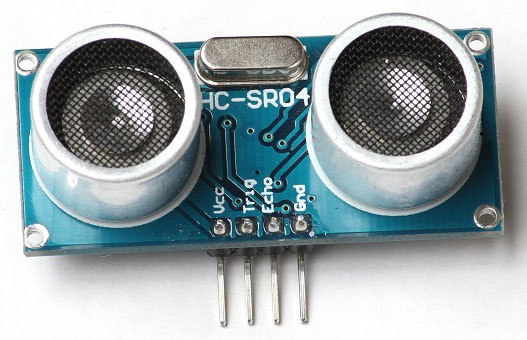
The sensor has 4 terminals:
- Vcc - 5V.
- Trig - Trigger signal to the sensor. The microcontroller delivers a 10 microsecond pulse to the sensor. The sensor initiates the metering process.
- Echo - Echo signal from the sensor to the microcontroller. The pulse duration is proportional to the measured distance.
- Gnd - Earth.
Here is the process of working with the sensor on the oscilloscope screen:

- Channel 1 - Trig
- Channel 2 - Echo
The microcontroller gives impulse to Trig . After that, the sensor responds with a pulse to Echo .
The pulse duration is proportional to the measured distance.
The measured distance is calculated using the formula (taken from the sensor specification):
distance (cm) = pulse width Echo (microseconds) / 58
According to the specification, the sensor can measure distances from 2 to 400 cm.
To measure the pulse duration with the predicted error without real-time will be problematic.
The measurement process may, for example, be superseded by the scheduler and the measurement result will be incorrect.
We connect HC-SR04 to the Intel Edison microcontroller

Components Used:
- Edison Compute Module
- Edison arduino board
- Grove Basic Shield
- Character screen Grove LCD RGB Backlight
- Ultrasonic distance sensor HC-SR04
- Bread board
First, connect the Edison Compute Module to the Edison Arduino board. Then connect the Grove Basic Shield expansion board to the Edison Arduino Board. Grove LCD RGB Backlight connects to the I2C connector on the Grove Basic Shield.
Ultrasonic distance sensor HC-SR04 connects to Grove Basic Shield as follows:
- Vcc to + 5V.
- Trig to pin # 3.
- Echo to pinu # 4.
- Gnd to Gnd.
Pins 3, 4 are randomly selected, others can be used instead.
Intel Edison Firmware Update
Microcontroller support is available in the Intel Edison® Board Firmware Software Release since version 2.1. If your firmware is older, then you need to update it.
You can find out the current firmware version with the command:
# configure_edison --version This example was created on firmware version 146.
The process of updating the firmware is described in detail in the article Flashing Intel Edison . Personally, I usually use the method described in the Alternate Flashing Method section.
Read the instructions carefully before flashing.
We connect Intel Edison through Ethernet-over-USB
To work with Edison from the MCU SDK environment, you need to create a network connection.
To do this, for example, connect a USB cable to the middle micro-USB port (the switch should be set to the side of micro-USB ports).
In Linux, the network is configured with the command:
# ifconfig usb0 192.168.2.2 Intel Edison IP Address:
192.168.2.15The connection process is described in more detail in the Connecting to your Intel® Edison board using Ethernet over USB article.
MCU SDK
A cross-platform development environment MCU SDK based on Eclipse has been released to create applications that will run on the embedded microcontroller. The installation process is described in detail in the article Installing the MCU SDK .
The MCU SDK allows you to create, compile, download to the board and debug applications for the microcontroller.
Interaction with MCU
To interact with a microcontroller from Linux several interfaces are available:
/dev/ttymcu0 - The channel for data exchange. From Linux, you can work with standard file operations. From the program on the microcontroller, the exchange is performed using the host_send and host_receive ./dev/ttymcu1 - The channel through which the microcontroller sends debug messages debug_print function./sys/devices/platform/intel_mcu/log_level - Allows you to set the level of debugging messages (fatal, error, warning, info, debug).Work with ports Edison Arduino Board
The microcontroller is built into the Edison Compute Module and controls the I / O ports located on the 70-pin connector of the module.
If you need to use a microcontroller with the Edison Arduino Board, then you need to find the matching GPIO port in the Edison Compute Module port number in the Edison Arduino Board.
Then you need to configure multiplexing and set the direction in the logic level converter.
When working with ports on the Linux level, all these actions are performed by the MRAA library. In the case of a microcontroller, you need to take care of this yourself using scripts (init_DIG.sh, init_i2c8.sh, init_mcu_PWM.sh, set_DIG.sh, read_DIG.sh, init_UART1.sh). For more information, see the Intel® Edison Kit for Arduino * Hardware Guide (table 4).
Linux program
A small Python script that will receive data from the embedded microcontroller and display it on a character display. To work with the symbolic display, we will use the Jhd1313m1 module from the UPM library.
Script show_distance.py:
import time import pyupm_i2clcd RET_ERROR = -1 if __name__ == '__main__': lcd = pyupm_i2clcd.Jhd1313m1(6, 0x3E, 0x62) with open('/dev/ttymcu0', 'w+t') as f: while True: f.write('get_distance\n') # Send command to MCU f.flush() line = f.readline() # Read response from MCU, -1 = ERROR value = int(line.strip('\n\r\t ')) lcd.clear() if value == RET_ERROR: lcd.setColor(255, 0, 0) # RED lcd.write('ERROR') else: lcd.setColor(0, 255, 0) # GREEN lcd.write('%d cm' % (value,)) time.sleep(1) Microcontroller software
The program on the microcontroller should, when receiving the get_distance command from the host, measure the distance and send the result to the host (distance in centimeters, or -1 in case of an error).
Configuring ports on the Edison Arduino Board:
./init_DIG.sh -o 3 -d output ./init_DIG.sh -o 4 -d input Let me remind you that the microcontroller works with GPIO ports on the Edison Compute Module, which differ from the numbering on the Edison Arduino Board. The correspondence table is shown, for example, at the end of the article Blinking an LED using the MCU .
Program for the microcontroller in the MCU SDK:
#include "mcu_api.h" #include "mcu_errno.h" // Arduino Extension PIN = 3 #define TRIG 12 // Arduino Extension PIN = 4 #define ECHO 129 // From HC-SR04 datasheet #define MIN_DISTANCE 2 #define MAX_DISTANCE 400 #define MAX_WAIT 10000 #define RET_ERROR -1 int get_distance() { // Send Trig signal to HC-SR04 gpio_write(TRIG, 1); mcu_delay(10); gpio_write(TRIG, 0); // Read Echo signal from HC-SR04 int i; i = 0; while ((gpio_read(ECHO) == 0) && (i < MAX_WAIT)) { mcu_delay(1); i++; } unsigned long t0 = time_us(); if (gpio_read(ECHO) == 0 || i == MAX_WAIT) { return RET_ERROR; } i = 0; while ((gpio_read(ECHO) == 1) && (i < MAX_WAIT)) { mcu_delay(1); i++; } unsigned long t1 = time_us(); if (gpio_read(ECHO) == 1 || i == MAX_WAIT) { return RET_ERROR; } unsigned long distance = (t1 - t0) / 58; if (MIN_DISTANCE < distance && distance < MAX_DISTANCE) { return distance; } else { return RET_ERROR; } } #define MAX_BUF 255 unsigned char buf[MAX_BUF]; void mcu_main() { // Setup Trig as OUTPUT gpio_setup(TRIG, 1); // Initially set Trig to LOW gpio_write(TRIG, 0); // Setup Echo as INPUT gpio_setup(ECHO, 0); while (1) { unsigned int len; len = host_receive(buf, MAX_BUF); if ((len >= 12) && (strncmp(buf, "get_distance", 12) == 0)) { unsigned int distance; distance = get_distance(); len = mcu_snprintf(buf, MAX_BUF, "%d\n", distance); host_send(buf, len); } } } Add script to autorun
Create a file that will run our script:
File /home/root/startup.sh
#!/bin/bash cd /home/root # configure PIN3 as GPIO OUPUT (TRIG signal) ./init_DIG.sh -o 3 -d output # configure PIN4 as GPIO INPUT (ECHO signal) ./init_DIG.sh -o 4 -d input python show_distance.py Mark scripts as executable:
# chmod a+x /home/root/startup.sh # chmod a+x /home/root/init_DIG.sh Since Yocto Linux uses systemd, to add a script to autorun, you need to create a file of the so-called “service”.
Create a file /lib/systemd/system/startup-script.service
[Unit]
Description = Startup User Script
After = syslog.target
[Service]
ExecStart = / home / root / startup.sh
[Install]
WantedBy = multi-user.target
Description = Startup User Script
After = syslog.target
[Service]
ExecStart = / home / root / startup.sh
[Install]
WantedBy = multi-user.target
Add a script to autorun:
# systemctl enable startup-script After the reboot, the measured distance should be displayed on the symbol display:

Resources used
- Intel Edison Board Software Downloads
- SparkFun Block for Intel Edison - Arduino
- Using the MCU SDK and API: Code examples
- Assembling the Intel® Edison board with the Arduino expansion board
- Flashing intel edison
- Connecting to your Intel® Edison board using Ethernet over USB
- MCU SDK
- Installing the MCU SDK
- MRAA library
- Intel Edison Kit for Arduino Hardware Guide
- Sample scripts for the MCU SDK
- UPM library
- UPM: Jhd1313m1 module
- Blinking an LED using the MCU
Source: https://habr.com/ru/post/260471/
All Articles