Interactive robot to control the smart home. Electronics Overview
We continue the story about Lexi. The Lexi project is a member of the information technology cluster of the Skolkovo Foundation. The article will appeal to anyone who is interested in the development of hard-core projects, who are interested in voice interfaces and the future of the smart home. The article provides a brief overview of the electronics that are used inside our device.
vk.com/rtrg?r=MyfvmSagVGcKoVRPBQ92U5CfxIhCPah9BpgCNi*VQ5Z*GZClBfq8O6Xqoc4FgyLmY/t2xfXW*b/pLNakil70J2BgItRALRcbqLdyvvbQaL48Y3InrmCX91lp3jlslzoTrQWAQ2odZccwu06QSKcDISHi4yplYcjlvQQqCvYweCs-&pixel_id=1000020818
The electronics review is conducted by Roman Zhukov, technical director of Lexi LLC. The novel is the key figure of the project. At the initial stages, he answered and fully implemented the following areas:
The text part of the review will add for clarity video:
')
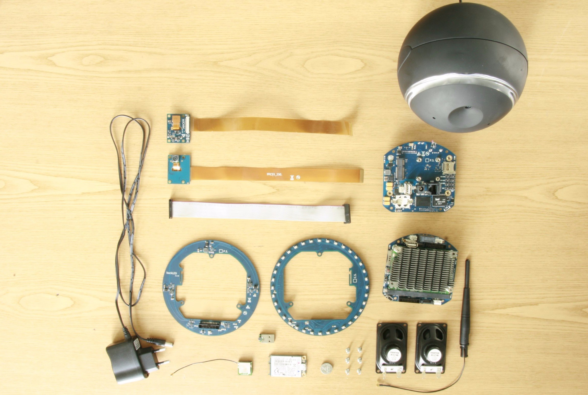
Initially, the device itself was assembled on ready-made hardware, which allowed us to quickly create a prototype operating in a limited mode for demonstrating it at presentations and working out the concept. At the moment we have all our electronics, made for our specific tasks and for our building.
We begin with the most important connective of the device: the computational module (Fig. 1) and the baseboard (Fig. 2).
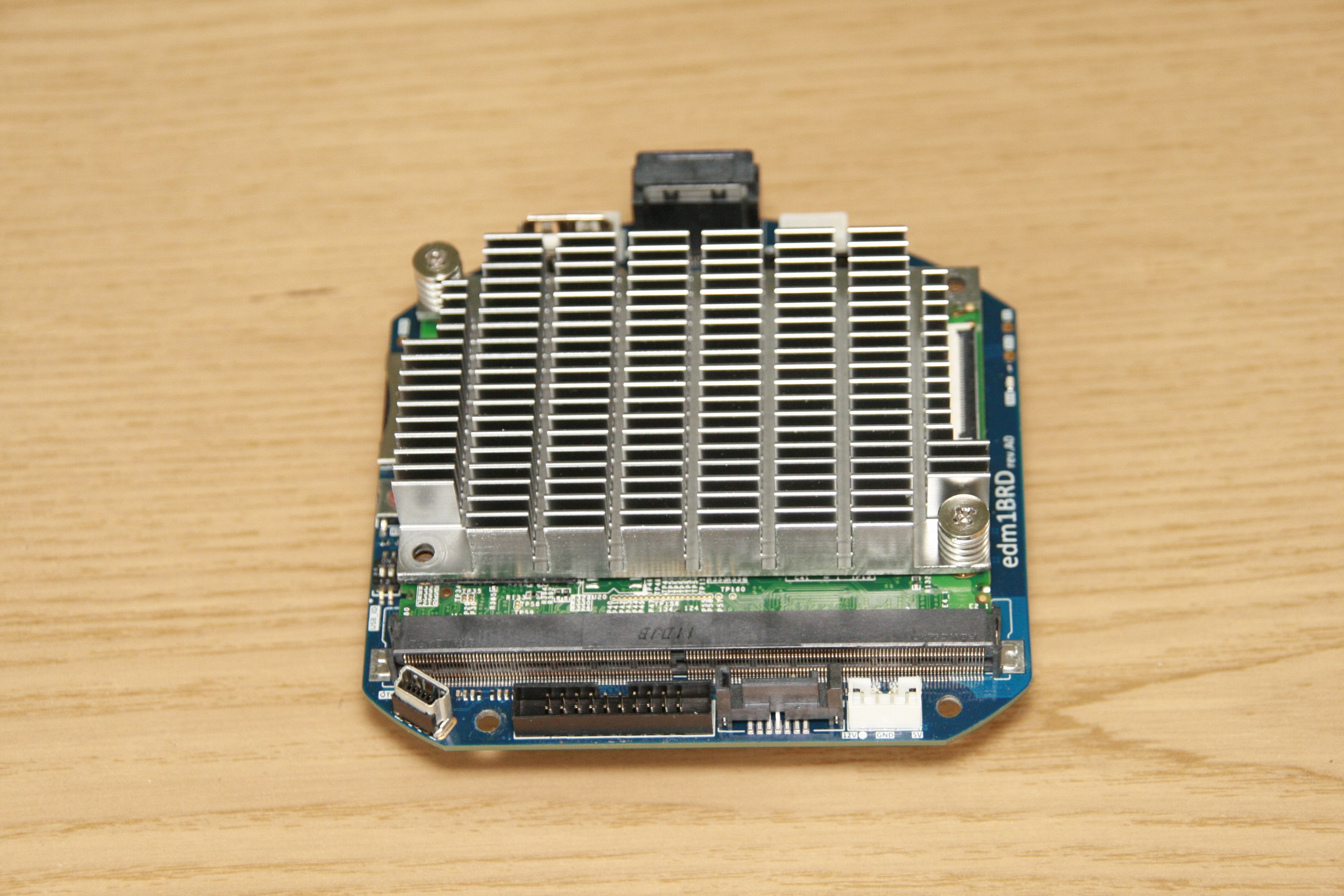
Fig. one
This is a very flexible bundle that allows you to maintain the device for many years. It is based on a special module, which is described by a special standard having industrial, automotive and commercial use. Constantly upgrading and maintaining in good condition the software for this module, you can develop and maintain the project for a long time.
Consider the elements that are on the base board. In addition to the computational module itself, which is inserted into the slot as a cartridge (generally removable, which improves maintainability), here you can find general-purpose connectors, such as USB, an HDMI connector (which is necessary, in our opinion, in order to use this fee in other projects), as well as for outputting debug information and testing at the factory.
We can even see the SATA connector, it is also present here, supported by the controller. This connector has been added as an expansion port for a project in the future.
Visible auxiliary connectors on the board, which allow you to debug devices - UART; special connectors that have vibration resistance and a system of guides, which reduces the likelihood of jumping out. Despite its unusual appearance, it is, in fact, a USB port, it transmits a signal to the sound module. Here we can also see a multi-pin connector, which provides power to the backlight boards, including power supply and signal transmission to the sound module. On the sides you can see the familiar mini-USB port - this port is designed to flash the board.
Now let's see what's on the back.

Fig. 2
This is the back (reverse) side of the board and it faces the back of the Lexi, where all the main ports fit: the power port, the port for installing external accessories. The device provides for the presence of external accessories in the process of its development; they can be different, mainly in order to emphasize the personality of Lexi (as individuals). Here we can also see the network port. This is a regular RJ45 connector, here we plug in the familiar twisted pair to connect the device to the Internet through a router, which can be required at the workplace in many places where there is no Wi-Fi connection. We see a battery that stores system time and is responsible for providing some other functions, like the battery that is installed on your motherboards inside a desktop computer. Everything else is a semiconductor snap-in that provides data storage (like an existing drive), a network converter, and a group jumper system, which is generally intended for Lexi's initial firmware, as well as for restoring its firmware during the time if it breaks.
Interesting is the location on the board of the special Mini PCI-Express connector. This port is intended for installation of a 3G or 4G modem (Fig. 3). In general, a product (as a product from the Internet of Things) can work without connecting to your wireless network using an operator’s mobile network. To do this, the product is complemented by a special modem, at the moment - by Huawei, through which the operation of this device is completely out of the box: got, stuck and your product on the Internet.
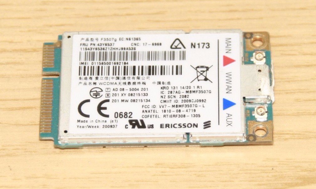
Fig. 3
That's all about the baseboard. We will not go into details and open this product, removing the radiator and many other components. In general, it is a standard strapping that stores data, connectors for antennas and much more. This is pure electronics.
Let us turn to the review of the other board. This is the board that provides the backlight in the device, but not only (Figure 4-5).
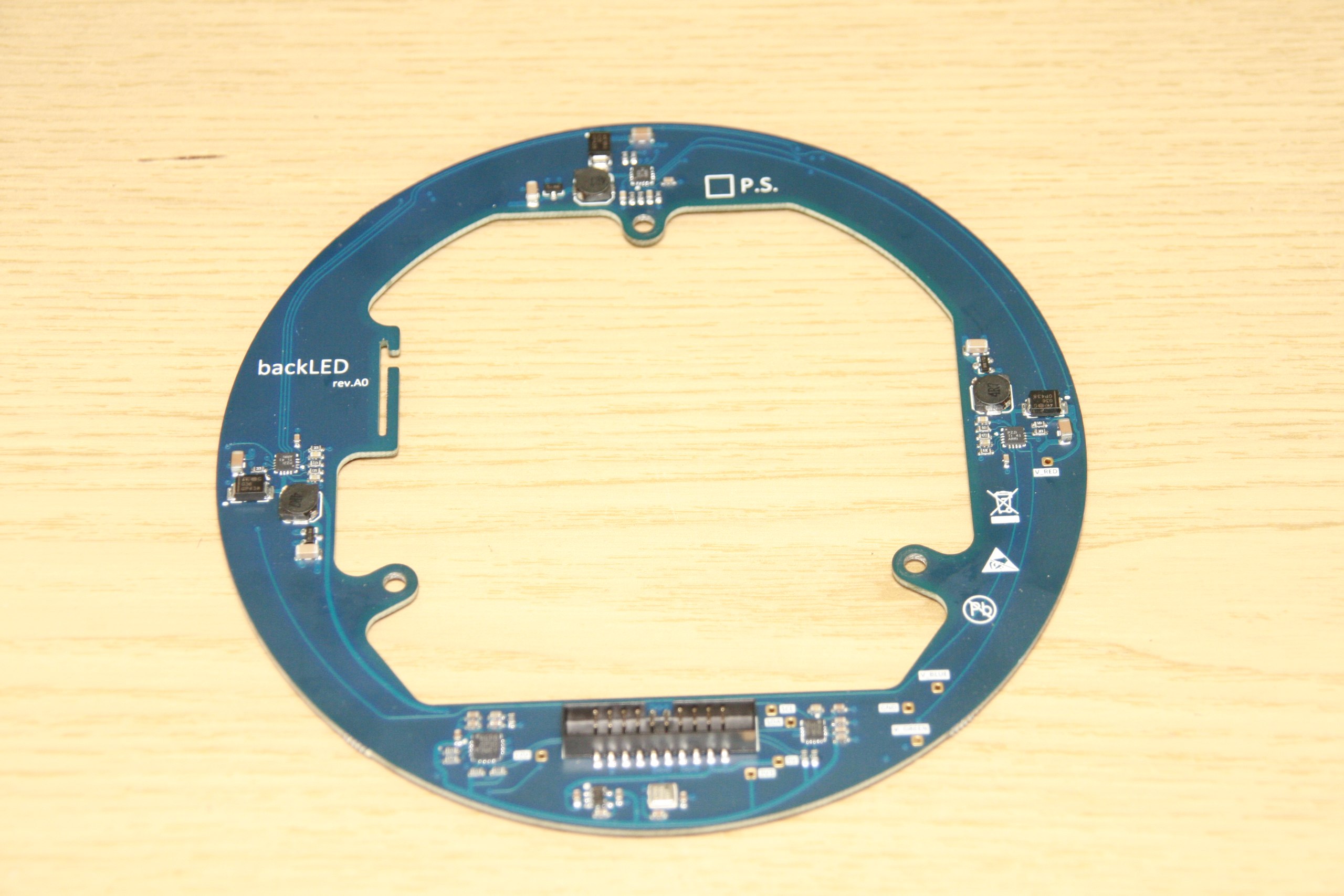
Fig. four

Fig. five
In fact, the board is multifunctional. On the front (Fig. 5) side there are many LEDs that can programmatically change their colors and intensity. Thus, Lexi can shine in different colors. In our project, the backlight plays the function of the non-verbal method of communication with the user in the process of dialogue - provides feedback to the interlocutor during communication.
Sensors are located on the reverse side of the board (Fig. 4), as well as a system of LED drivers ensuring their operation. Sensors were removed from the baseboard; in general, these are sensors that personalize Lexi as a device. They recognize his movement, are able to determine the temperature and pressure and transmit this information through voice communication with the user.
Here we see the return port, which was familiar to us, which was on the base module. Through it data transfer and power supply of this module is carried out. As you may have noticed, the module has an unusual round shape, and in the center the material is missing because the sound module is mounted in the center of the board, which is not in this review.
We will tell about our sound module in the second review. In it, we can highlight important issues that you may have in the course of the review.
Transmit data and feed the boards inside this device like this kind of cables (Fig. 6).

Fig. 6
There is also an interesting implementation of a flexible printed circuit board that transmits signals for a video camera (Fig. 7). A special photo / video camera located on its module, with a 5 Mpx resolution matrix, performs photo and video shooting, recognizes your presence in front of the device, allows Lexie to communicate with you independently, detecting you automatically.
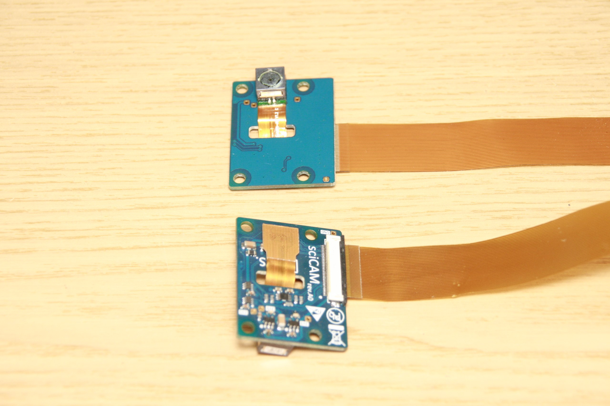
Fig. 7
Inside the product, special whip antennas are installed in one row (Fig. 8). These antennas have high enough power for reliable signal reception in both 3G and 4G mode, as well as Wi-Fi and Bluetooth. All this passes through a special chip, which is located on the board. In the general case, antennas are connected by a special connector located inside the parting.
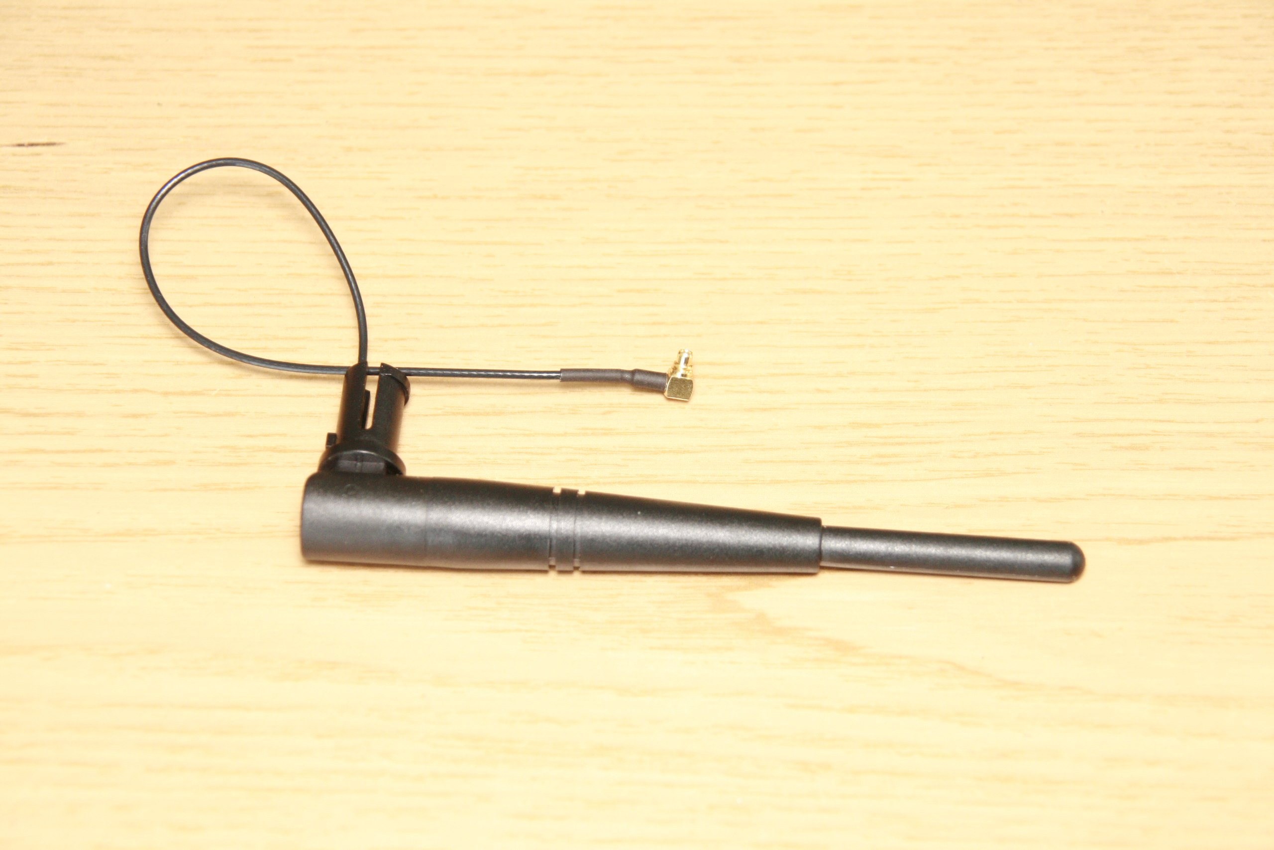
Fig. eight
In particular, we tested a special printed-type antenna in the design (Fig. 9), which are generally glued or mounted on one of the boards and reduce the antenna dimensions, but in general they showed themselves worse than a whip antenna. Thus, whip antennas, as they fit well in the case, most likely, will be left.

Fig. 9
All internal components were designed and developed taking into account multiple connections during the development of the robot.
An interesting view have the speakers (Fig. 10), which are used to output sound. They have a very unusual shape: rectangular. Their shape is due to the fact that the device has a rounded shape, there is little space inside and, from the design point of view, the narrow elongated speakers approached us more than others. These are very high-quality German speakers that have a frequency response designed for voice output.

Fig. ten
Lexi is powered via an ordinary power supply with a male connector. This is an absolutely standard power supply. At the output, it gives 12V, consumes quite a few watts, it is powered from a standard 110-220V outlet.
This concludes our brief overview of Lexi electronics.
After all, we want to announce two events:
Most effectively, our project can be monitored on social networks:
vk.com/rtrg?r=MyfvmSagVGcKoVRPBQ92U5CfxIhCPah9BpgCNi*VQ5Z*GZClBfq8O6Xqoc4FgyLmY/t2xfXW*b/pLNakil70J2BgItRALRcbqLdyvvbQaL48Y3InrmCX91lp3jlslzoTrQWAQ2odZccwu06QSKcDISHi4yplYcjlvQQqCvYweCs-&pixel_id=1000020818
The electronics review is conducted by Roman Zhukov, technical director of Lexi LLC. The novel is the key figure of the project. At the initial stages, he answered and fully implemented the following areas:
- Industrial Design;
- tooling for manufacturing;
- electronics;
- image embedded linux;
- organization of production in China.
The text part of the review will add for clarity video:
')
Initially, the device itself was assembled on ready-made hardware, which allowed us to quickly create a prototype operating in a limited mode for demonstrating it at presentations and working out the concept. At the moment we have all our electronics, made for our specific tasks and for our building.
We begin with the most important connective of the device: the computational module (Fig. 1) and the baseboard (Fig. 2).
Fig. one
This is a very flexible bundle that allows you to maintain the device for many years. It is based on a special module, which is described by a special standard having industrial, automotive and commercial use. Constantly upgrading and maintaining in good condition the software for this module, you can develop and maintain the project for a long time.
Consider the elements that are on the base board. In addition to the computational module itself, which is inserted into the slot as a cartridge (generally removable, which improves maintainability), here you can find general-purpose connectors, such as USB, an HDMI connector (which is necessary, in our opinion, in order to use this fee in other projects), as well as for outputting debug information and testing at the factory.
We can even see the SATA connector, it is also present here, supported by the controller. This connector has been added as an expansion port for a project in the future.
Visible auxiliary connectors on the board, which allow you to debug devices - UART; special connectors that have vibration resistance and a system of guides, which reduces the likelihood of jumping out. Despite its unusual appearance, it is, in fact, a USB port, it transmits a signal to the sound module. Here we can also see a multi-pin connector, which provides power to the backlight boards, including power supply and signal transmission to the sound module. On the sides you can see the familiar mini-USB port - this port is designed to flash the board.
Now let's see what's on the back.
Fig. 2
This is the back (reverse) side of the board and it faces the back of the Lexi, where all the main ports fit: the power port, the port for installing external accessories. The device provides for the presence of external accessories in the process of its development; they can be different, mainly in order to emphasize the personality of Lexi (as individuals). Here we can also see the network port. This is a regular RJ45 connector, here we plug in the familiar twisted pair to connect the device to the Internet through a router, which can be required at the workplace in many places where there is no Wi-Fi connection. We see a battery that stores system time and is responsible for providing some other functions, like the battery that is installed on your motherboards inside a desktop computer. Everything else is a semiconductor snap-in that provides data storage (like an existing drive), a network converter, and a group jumper system, which is generally intended for Lexi's initial firmware, as well as for restoring its firmware during the time if it breaks.
Interesting is the location on the board of the special Mini PCI-Express connector. This port is intended for installation of a 3G or 4G modem (Fig. 3). In general, a product (as a product from the Internet of Things) can work without connecting to your wireless network using an operator’s mobile network. To do this, the product is complemented by a special modem, at the moment - by Huawei, through which the operation of this device is completely out of the box: got, stuck and your product on the Internet.
Fig. 3
That's all about the baseboard. We will not go into details and open this product, removing the radiator and many other components. In general, it is a standard strapping that stores data, connectors for antennas and much more. This is pure electronics.
Let us turn to the review of the other board. This is the board that provides the backlight in the device, but not only (Figure 4-5).
Fig. four
Fig. five
In fact, the board is multifunctional. On the front (Fig. 5) side there are many LEDs that can programmatically change their colors and intensity. Thus, Lexi can shine in different colors. In our project, the backlight plays the function of the non-verbal method of communication with the user in the process of dialogue - provides feedback to the interlocutor during communication.
Sensors are located on the reverse side of the board (Fig. 4), as well as a system of LED drivers ensuring their operation. Sensors were removed from the baseboard; in general, these are sensors that personalize Lexi as a device. They recognize his movement, are able to determine the temperature and pressure and transmit this information through voice communication with the user.
Here we see the return port, which was familiar to us, which was on the base module. Through it data transfer and power supply of this module is carried out. As you may have noticed, the module has an unusual round shape, and in the center the material is missing because the sound module is mounted in the center of the board, which is not in this review.
We will tell about our sound module in the second review. In it, we can highlight important issues that you may have in the course of the review.
Transmit data and feed the boards inside this device like this kind of cables (Fig. 6).
Fig. 6
There is also an interesting implementation of a flexible printed circuit board that transmits signals for a video camera (Fig. 7). A special photo / video camera located on its module, with a 5 Mpx resolution matrix, performs photo and video shooting, recognizes your presence in front of the device, allows Lexie to communicate with you independently, detecting you automatically.
Fig. 7
Inside the product, special whip antennas are installed in one row (Fig. 8). These antennas have high enough power for reliable signal reception in both 3G and 4G mode, as well as Wi-Fi and Bluetooth. All this passes through a special chip, which is located on the board. In the general case, antennas are connected by a special connector located inside the parting.
Fig. eight
In particular, we tested a special printed-type antenna in the design (Fig. 9), which are generally glued or mounted on one of the boards and reduce the antenna dimensions, but in general they showed themselves worse than a whip antenna. Thus, whip antennas, as they fit well in the case, most likely, will be left.
Fig. 9
All internal components were designed and developed taking into account multiple connections during the development of the robot.
An interesting view have the speakers (Fig. 10), which are used to output sound. They have a very unusual shape: rectangular. Their shape is due to the fact that the device has a rounded shape, there is little space inside and, from the design point of view, the narrow elongated speakers approached us more than others. These are very high-quality German speakers that have a frequency response designed for voice output.
Fig. ten
Lexi is powered via an ordinary power supply with a male connector. This is an absolutely standard power supply. At the output, it gives 12V, consumes quite a few watts, it is powered from a standard 110-220V outlet.
This concludes our brief overview of Lexi electronics.
In subsequent publications, we plan to cover the following topics:
- Sound module overview.
- The organization of the smart home system with the help of Lexi.
- Lexi as an intellectual interactive educational toy for children.
- The technologies used in the Lexi project are based on recommender systems.
- Sound capture using an array of microphones.
- Speech recognition.
After all, we want to announce two events:
- Launch a new Kickstarter campaign. Leave your contact information in a special form and be the first to know everything: goo.gl/hxEEjr .
- Begin beta testing of our device. You can take part in testing the Lexi beta version by leaving your application in our Vkontakte community: vk.com/topic-67233059_31971920 .
Most effectively, our project can be monitored on social networks:
- vk.com/lexybot
- facebook.com/lexyRobot
- twitter.com/lexy_ai
- youtube.com
We are waiting for questions in the comments! Thanks for attention!
Source: https://habr.com/ru/post/260363/
All Articles