Challenge the tradition of hi-fi. Digital potentiometers in detail. Part two
It came as a surprise to me that the most heated debates in the discussion of my previous article related primarily to the possibility of using digital impedances as an audio volume control in HiFi equipment. In order to clarify this issue, I decided to devote a separate article to a detailed analysis of high-quality volume control circuitry with a switching impulse noise suppression circuits based on the VDAC AD9252. In addition to circuitry, you will also be able to get acquainted with the characteristics achieved under the cut.
For those who have not read my yesterday's article, which dealt with general issues relating to digital resistances, I strongly recommend that you first read it here . Firstly, you better understand what is actually being discussed below, and secondly, if you are interested in today's topic, then you will find interesting material in it.
')
In order to bring the promised examples of real-world circuits of software-controlled value converters, tunable filters, and other electronic nodes, the parameters of which can be changed using digital resistance will have to write a third article. I will try to do this in the near future, but for now I propose to investigate whether the volume control assembled on the basis of the top device from ADI draws on HiFi equipment, or
I present an attempt to create a volume control based on one of the top chips of ADI digital controllers, claiming to be Hi-Fi.
To begin with, I will give general characteristics that we managed to squeeze. Low harmonic distortion. Normalized transfer characteristic. The dynamic range of volume control is 46 dB. In addition, there is the possibility of a MUTE function with a signal attenuation of 130 dB. The regulator enters this mode after the AD5292 regulator enters the shutdown mode, by issuing a special command. And of course there is a special scheme to reduce the effect of the occurrence of hearing impulse noise at the moment of switching the volume level. This effect is most pronounced in logarithmic amplifiers, because their volume can change abruptly in a very wide range. To reduce the noise when switching the volume level to the minimum, this switch must be made when the signal passes through zero.
The regulator can operate with an input signal level up to ± 14 volts (10 V RMS), which provides good noise performance. The maximum load current at the output of 20 mA. Management by SPI interface. The interface for connecting the microcircuit to the control microcontroller is not shown, since it is standard.
The scheme and principle of its work

The signal from the input repeater is fed to the AD5292 level regulator with a logarithmic characteristic. A part of the signal is branched off from the ground using a voltage divider on resistors R4 and R5, loaded on an AD8541 op amp, which acts as a dynamic load forming an artificial earth at 1.81 V. The signal goes to the U3 and U4 comparators, which form a window at 13 millivolts in the area where the signal passes through zero. At the time the signal passes through zero, the logic element U5A forms a low level.
In order to switch the volume level, it is necessary to write new data to the buffer register and apply a negative front to the input of the SYNC U6. When, after writing the code, we feed a low level to the lower input of the U5B, it is transmitted to the switching level of the digital impedance value only at the moment the audio signal passes through the “window” of the comparators. Please note that to improve the accuracy of the entire circuit only works on DC.
To obtain the most comfortable for the ear volume control characteristics, the average output of the digital resistance is shunted by the resistor R8. As a result, we obtain the normalized characteristic of signal transmission, shown in the figure below.

Illustration of the operation of the impulse noise reduction circuit
Let's first see what happens when switching the resistance level in the disconnected impulse noise suppression circuit.
This is what the transient process looks like at the moment of switching on the sound that occurred at the time marked with zero.

For the case of switching the sound from one value to another, everything may look even worse.

The following picture shows the result of the operation of our jamming circuit during the transition from higher volume to lower volume.

Regulator Characteristics
Now let's look at the other characteristics that have been achieved in our controller.
As rightly pointed out by the respected Alex013 in the comments to my previous article, the sound quality depends quite strongly on the level of odd harmonics of the signal in the amplifier path. In order to show how they are affected by our digital controller, let's consider the result of FFT conversions of a 1 KHz signal passing through the circuit with a “potentiometer slider” set to the most accurate position — that is, the transfer coefficient is equal to one.

In my opinion, the characteristics are very decent, the level of the third harmonic went below -100 dB, the fifth one is not visible at all with the naked eye. I wonder what our sound experts will say.
I give the following chart specifically for the barabanus habourer. I

At a frequency of 1 kHz, our circuit provides a total level of signal distortion at -93 dB. The dependence of the circuit's own noise level and non-linear distortions on the signal frequency at the amplifier transmission ratio equal to one is shown in the graph below.

Option schemes for lovers of compromise.
We’ll finish our study with this scheme, and as a bonus I offer its simplified version, with somewhat worse characteristics, but with a more accessible element base.

But the oscillogram of the process of switching the volume level at a very high frequency. As you can see, nonlinear distortions at the moment of switching were not cost, but there are no emissions that can be cut ear!

Thanks to read to the end. I will try to test your patience a little longer. Since I am not an expert in the field of "pure transparent sound" and it is difficult for me to assess the quality of the described device, I ask you to express your opinion in the form of an answer to a question or in comments.
Link to the previous article in the series: “When the DAC does not help. Digital potentiometers in detail. Part one"
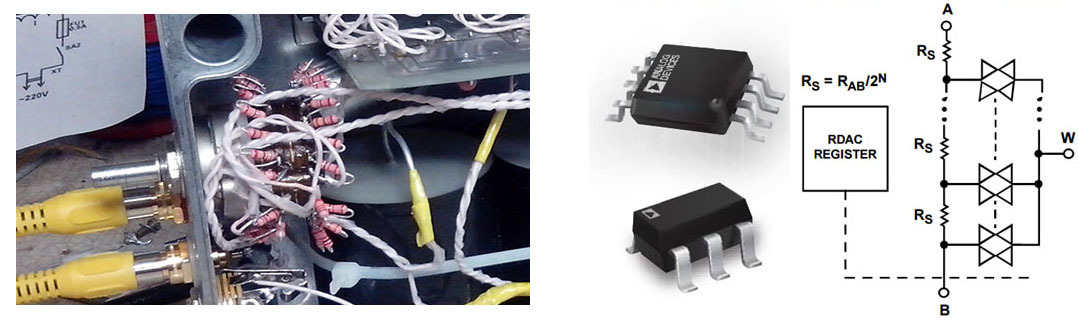
The article uses a fragment of the photo of the user's tube amplifier eta4ever .
Source: https://habr.com/ru/post/260273/
All Articles