Ingredients of IoT Fast Food Delicacies: Intel Edison + Intel XDK + JavaScript + Grove Kit
How fast can you create a device for the Internet of Things (IoT), which is controlled through a browser, receives and transmits information, given that you have never worked with microcontrollers, but only engaged in high-level JavaScript programming?
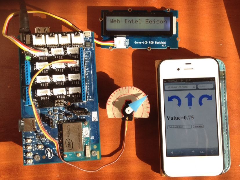
For example, such a device as in the photo. It has an LCD screen and a dial gauge on the servo. Nearby is a phone with a running browser that is connected to the web server on the device. When you click the arrows in the browser, the pointer is rotated to the right, left or set to the neutral position. After setting the value, it is passed back to the browser and is shown as the Value value. Additionally, in the browser, you can set a text string, which after pressing the “Set text” button is displayed on the LCD screen. All interaction takes place over Wi-Fi. How long do you think it will take to develop?
If you think about it, you have a lot to do. Write code in C / C ++, which runs on the device and interacts with the sensors, raise the web server, implement the backend, the front end, and put it all together. In fact, everything is much simpler. And I dare say that an hour is enough for everything about everything. Why? Yes, because there are ready-made solutions that can be combined and, thus, quickly make a prototype. We'll take the Intel Edison board, the Intel XDK IoT Edition development environment, the Grove Kit sensor set, and just one programming language — JavaScript. Yes, no C / C ++. It's simple, right out of the box.
')
I will talk about everything in order, starting from the very beginning, so that even an unprepared developer is not lost. Well, in the end we will look at the example described at the beginning.
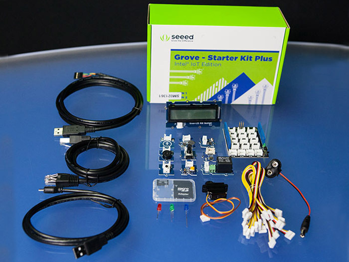
The Grove Starter Kit is a great thing. I know that some programmers are afraid to work with radio electronics. There are all kinds of wires, connections, soldering, radio components ... But this kit allows you to simplify the work. All sensors are connected universally using standard connectors, which, if they so desire, cannot be connected incorrectly. All connectors on the expansion card are signed. It is enough to connect the necessary wires to the sensors and you can focus on the software part of the device.
The kit includes:
Of course, you can buy sensors and connect them yourself. Yes, it will be cheaper, but here all the connectors are standard, all the wires are already in stock. Even I, who are not frightened by soldering, are much more pleasant to simply plug in connectors and think not about where the wiring is, but about the program itself. Moreover, I had a situation on the hackathon , when I quickly connected the sensors before the demonstration, I messed up the wires, supplying power to the sensor output. Fortunately, nothing burned.
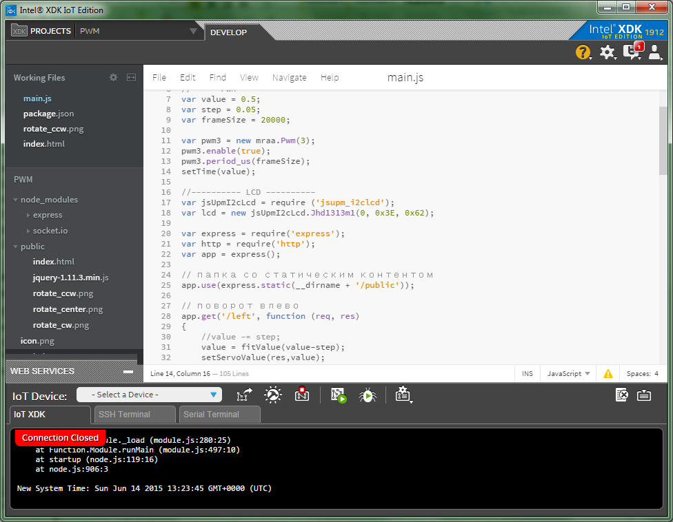
The Intel XDK development environment allows you to create a JavaScript application on Node.js and run them on the Intel Edison and Intel Galileo boards. This allows those developers who have previously written in JavaScript mainly for the web to try their hand at something new. The advantage is that if earlier, in order to write for a microcontroller, you had to know C / C ++, now everything becomes much easier. You just write your program on your favorite JavaScript, and it works.
It is possible that an application written in JavaScript will be inferior in speed to the same, but in C ++. But the fact is that the code is easier to write, yes, and the hardware is powerful now. The advantage of the Intel XDK is also in the fact that downloading and launching the application onto the board with all the associated libraries and files is done by pressing a couple of buttons.
Again I will give an example from the hakaton. One of the teams told that they had long suffered from the implementation of their project. We tried to make it work on both Python and C ++. But just by going to JavaScript, everything turned out right away.
Sometimes the XDK could not connect to Edison. In this case, the board worked on the serial port (emulation via USB). The check showed that the WiFi on the board was not working. It turned out that in my version of the board firmware there was a bug. When you work with the D7 connector, Wi-Fi starts to work poorly. After that, it is very problematic to make the board work normally. Since the program starts automatically when the board is restarted. I decided to only connect to USB with serial port emulation. Having connected, I fixed the program so that it did not address D7 and restarted the board.
I assume that you have already connected the Intel Edison board to a computer via USB or WiFi. If not, then there are several ways. You can enable serial port emulation via USB, this is an extreme microUSB connector. You can enable USB network interface emulation, this is the middle microUSB connector. You can use wifi. Power can be connected via USB or using a power supply.
To simplify the work with sensors from JavaScript there are special libraries. One of them is MRAA. It provides a fairly low level of work with the board.
http://iotdk.intel.com/docs/master/mraa/index.html - MRAA Documentation
Its main task is to set up a pin for input or output, output a zero or one, read the value of a digital or analog signal from a contact. Can configure the pin to work in PWM (PWM) mode and set its parameters. This is enough to blink the LED, read the state of the button, get the temperature value from the sensor, turn on the servo.
Here, for example, the program to enable the on-board LED:
But if you need to manage something more complicated, for example, an LCD screen, then this is not enough.
The next library is UPM. It provides a higher level of work.
http://iotdk.intel.com/docs/master/upm/node/ - UPM documentation for Node.JS
The library implements algorithms for controlling complex devices, such as screens, servomotors, etc. Otherwise, this would have to be done independently. We will use it to control the LCD screen on the I2C serial bus.
An example of a program that displays text on an LCD screen:
When you create an application in Intel XDK on a computer, you upload it to the board (the Upload button). It will be placed in a folder, but will not run. The project is located on the board in the /home/root/.node_app_slot folder. This link is configured from the root / node_app_slot
The application sent to the board can be launched in two ways. Or directly from the development environment with the Run button. Or manually in the console on the board, for this you need to go to the / node_app_slot folder and execute the command
If you restart the Edison board, the application starts automatically. To prevent this from happening, you can either remove the start of the daemon from the autorun, or remove or rename the main.js file, which is easier.
Now we will look at all the sensors that come with the Grove Starter Kit Plus (Intel IoT Edition) in groups by connection type.
All these devices are connected to a digital output. You can use D2-D8. When the unit is fed, they turn on, turn off at zero.
Included are three LEDs - red, blue and green. Choose any. The LED device is polar, so it is important to connect it correctly. It is necessary to insert the LED so that the long leg (anode) is in the slot marked with “+”. But if you connect wrong, it just will not shine.
Connect it to D2 and blink.
Buzzer or squeaker. When voltage is applied, it starts beeping at the same frequency. Connects to a digital output. You can use the code as for with the LED.
A relay is a switch that is controlled by a signal. When a unit is applied, the switch closes the contacts; when applying a zero, it opens. It can be used to control devices that are rated for voltages greater than 5V and currents greater than 0.5A and therefore are connected to an external power source. For example, you can turn on the desk lamp. The relay that comes with Grove has options of 10A x 250V. It is 2.5 kW. But this is the ultimate power. I think the kettle should not be included in this way. And if you switch the device with a supply voltage of 220 V, be careful, firstly, the voltage itself is dangerous to health, and secondly, if it gets onto the board, then it will most likely burn.
And what if we want to produce an analog signal of the intermediate level, and not just zero and one? Or how to turn on the LED at half brightness, if it has only two states? This can be achieved using PWM - Pulse Width Modulation (PWM - Pulse-width modulation). When used, the signal periodically changes from 1 to 0.
This happens every frame. When the time of both levels is the same, then on average we get a value of 0.5. Suppose the unit was 25% of the time, then the signal is the same, 0.25 of the maximum. If we control the LED like this and the frame is chosen small enough, then due to the inertia of our vision we will see this average brightness value.
Part of the digital connectors on the board can work in PWM mode, on the shield it is D3, D5, D6. (On the Edison board itself, they are labeled with a "~").
To enable PWM you need to set several parameters. The first is the repetition period of the signal, i.e. the frame size. The second parameter is the time during which there will be one. It can be set either as a factor of 0-1, or as a time value in ms.
Here is an example in which the LED will flash, gradually changing its brightness.
The buttons are connected to the digital inputs D2-D8. Give the unit if they clicked. The difference from each other is that the touch button is a capacitive sensor and therefore triggers from a light touch and works even through a layer of paper.
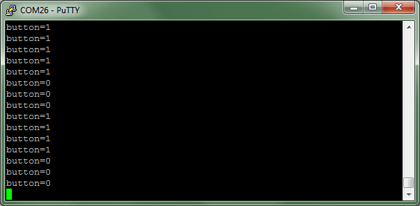
Create an application that will display the state of the button.
Connect the button to the D8:
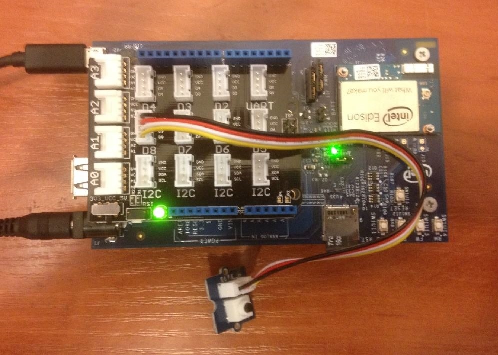
If, after launching, you press a button, you will see something similar.
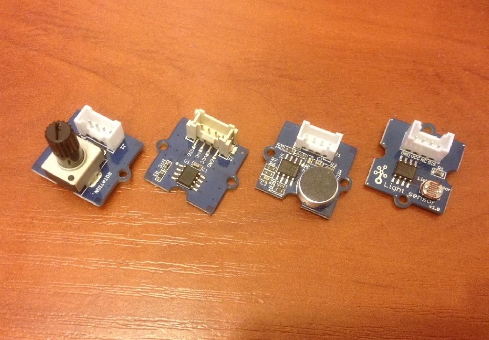
All these sensors produce an analog signal of different levels depending on the external influence on them. Connect to analog inputs A0-A3. The signal value is 0-1023.
Returns the angle at which it is rotated. Values range from 0-1023.
Connect it to A0.
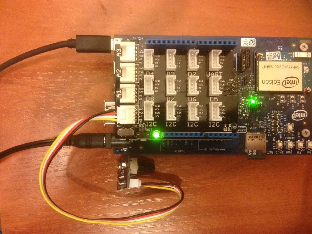
When you start the program and rotate the knob, you will see something like this.
As you can guess, it returns the temperature value. But it is not enough just to count the value, since this will be the relative resistance of the thermistor. To convert to degrees, it is better to use the UPM library. So, let's connect the sensor to A0.
The library function returns only an integer value. If you need a more accurate value, you can use the following code, which uses the value directly from the sensor.
The microphone produces a sound level. Connect to A1. Values, as usual for an analog input, are in the range from 0 to 1023.
A more interesting thing is the servo drive, this is a motor that turns at a given angle (0-180 degrees) and tries to maintain this position.
To set the angle, it is necessary to apply a pulse of a certain duration (duty cycle). Such impulses must come constantly, usually 50 times per second (20 ms). But the period of arrival is not so important, the duration is important. It can be from 500 μs to 2000 μs. With a minimum pulse value, an angle of 0 degrees is established, with a maximum of 180 degrees.
For different servo drives, the pulse widths may vary. They can be selected experimentally. But you have to be careful. If the duration value is outside the allowable range, then the servomotor starts to knock and heats up very much. Immediately disconnect it from the connector! When working properly, it should turn to a given angle, stop and shut up, while remaining cold.
We will use a digital output that can output a PWM signal. These are pins D3, D5, D6.
It should be noted that due to the fact that PWM can only accept 256 values as an input and it’s impossible to use all the values for filling, but only a small part, it turns out that the servo does not have many fixed angles, I got about 20.
The screen is more complex than the LED, so it connects to a special I2C serial bus.
The screen can display text in 2 lines of 16 characters each. There are RGB lights. The documentation says that it supports English and Japanese, and there is the ability to add a certain number of its characters.
Since the devices are connected to the I2C bus in parallel, all the connectors on the board are equivalent, and the screen can be inserted into any of them.
We use the UPM library.
http://iotdk.intel.com/docs/master/upm/node/classes/jhd1313m1.html - work with this screen.
So we looked at all the devices that are in the Grove Starter Kit Plus. Let's try to collect something more interesting that simultaneously uses several modules.
We will have a rotation sensor (A0), during rotation of which the servo (D3) will turn to the appropriate angle. The found pulse width of the PWM to rotate at this angle will be displayed on the LCD screen (I2C).
Since we are considering developing for IoT (Internet of Things), we need to make it possible to work with the device via the Internet. The following example creates a web server that displays the current temperature on a temperature sensor. The server listens to port 1337 and responds to the request to the site root. The temperature sensor is connected to A0. If your card has an address of 192.168.0.105, then in the browser indicate 192.168.0.105:1337.
Work example:
So, promised at the very beginning. Create a device controlled via a browser with an arrow on the servo and a screen. And with each turn command from the client, it will return the actual set value in JSON format, since no turn occurs in the extreme positions. And as a small bonus, you can send text to the connected LCD screen.
The program consists of two parts. One of them is on the Edison device. This is a web server, main.js file. It responds to requests from the client, servicing the servo and screen. Uses the library express and http.
The second part is on the client in the browser. It receives commands from the user and sends them to the server. Receives data from a web server in JSON format and displays it. Uses jQuery library.
This application will be a little more complicated. In the project, create a public folder, put static content in it. In our case, these are three images for the buttons - rotate_ccw.png, rotate_cw.png, rotate_center.png, html-file index.html, which is displayed in the client’s browser and the jquery-1.11.3.min.js library (It will need to be downloaded from official website jquery.com/download )
On the client, the script monitors clicking on the images of arrows and when such an event occurs, sends a request to the server at the corresponding address / right, / left, / center and waits to receive JSON data with information about the position of the arrow. When you click on the "Set text" button, the text from the input field is sent to the server.
On the board, the screen is connected to I2C. Servo connects to D3. The server listens to port 1337. The application is waiting for the appeal to / right. With such a request, if possible, it is rotated to the right and a JSON response is sent with information about the position of the arrow. An appeal to / left and / center is handled similarly. If you type / text / abcdef, the string abcdef will be displayed on the LCD screen. Work with the servo and the screen was discussed earlier.
Image rotate_ccw.png

Image rotate_cw.png

Image rotate_center.png

That's all. We start and check.
A few words about how demons work on the Intel Edison board.
The system is running the xdk-daemon daemon. If you stop it with the command:
then the running Node.JS application will stop. You can restart it with the command:
or restart:
The program can be edited directly on the board (vi), just do not forget to restart it after the change. Either way:
Or, if the program was launched in the console via the command:
then you can stop it through <Ctrl> + <C>
» Play audio on Intel Edison via Bluetooth using the Advanced Audio Distribution Profile (A2DP)
Installing OpenCV 3.0.0-rc1 (using IPP and TBB) on Intel Edison Yocto. USB camera in OpenCV
» Use the Intel Edison board to change the color of the Orbotix Sphero ball when new tweets appear
» Connect to Intel Edison via Android with Bluetooth LE (BLE)
For example, such a device as in the photo. It has an LCD screen and a dial gauge on the servo. Nearby is a phone with a running browser that is connected to the web server on the device. When you click the arrows in the browser, the pointer is rotated to the right, left or set to the neutral position. After setting the value, it is passed back to the browser and is shown as the Value value. Additionally, in the browser, you can set a text string, which after pressing the “Set text” button is displayed on the LCD screen. All interaction takes place over Wi-Fi. How long do you think it will take to develop?
If you think about it, you have a lot to do. Write code in C / C ++, which runs on the device and interacts with the sensors, raise the web server, implement the backend, the front end, and put it all together. In fact, everything is much simpler. And I dare say that an hour is enough for everything about everything. Why? Yes, because there are ready-made solutions that can be combined and, thus, quickly make a prototype. We'll take the Intel Edison board, the Intel XDK IoT Edition development environment, the Grove Kit sensor set, and just one programming language — JavaScript. Yes, no C / C ++. It's simple, right out of the box.
')
I will talk about everything in order, starting from the very beginning, so that even an unprepared developer is not lost. Well, in the end we will look at the example described at the beginning.
Grove Starter Kit Plus - Intel IoT Edition Gen2
The Grove Starter Kit is a great thing. I know that some programmers are afraid to work with radio electronics. There are all kinds of wires, connections, soldering, radio components ... But this kit allows you to simplify the work. All sensors are connected universally using standard connectors, which, if they so desire, cannot be connected incorrectly. All connectors on the expansion card are signed. It is enough to connect the necessary wires to the sensors and you can focus on the software part of the device.
The kit includes:
- Expansion card, with connectors for standard connection of all sensors.
- Light-emitting diode.
- Buzzer.
- Relay.
- The button is normal.
- Touch button.
- Rotation sensor
- Thermometer.
- Microphone.
- Light sensor.
- Servo.
- LCD screen.
- Wires with connectors.
- USB connectors.
- Connector for battery type Krone.
Of course, you can buy sensors and connect them yourself. Yes, it will be cheaper, but here all the connectors are standard, all the wires are already in stock. Even I, who are not frightened by soldering, are much more pleasant to simply plug in connectors and think not about where the wiring is, but about the program itself. Moreover, I had a situation on the hackathon , when I quickly connected the sensors before the demonstration, I messed up the wires, supplying power to the sensor output. Fortunately, nothing burned.
Intel XDK IoT Edition Development Environment
The Intel XDK development environment allows you to create a JavaScript application on Node.js and run them on the Intel Edison and Intel Galileo boards. This allows those developers who have previously written in JavaScript mainly for the web to try their hand at something new. The advantage is that if earlier, in order to write for a microcontroller, you had to know C / C ++, now everything becomes much easier. You just write your program on your favorite JavaScript, and it works.
It is possible that an application written in JavaScript will be inferior in speed to the same, but in C ++. But the fact is that the code is easier to write, yes, and the hardware is powerful now. The advantage of the Intel XDK is also in the fact that downloading and launching the application onto the board with all the associated libraries and files is done by pressing a couple of buttons.
Again I will give an example from the hakaton. One of the teams told that they had long suffered from the implementation of their project. We tried to make it work on both Python and C ++. But just by going to JavaScript, everything turned out right away.
The difficulties that were in developing
Sometimes the XDK could not connect to Edison. In this case, the board worked on the serial port (emulation via USB). The check showed that the WiFi on the board was not working. It turned out that in my version of the board firmware there was a bug. When you work with the D7 connector, Wi-Fi starts to work poorly. After that, it is very problematic to make the board work normally. Since the program starts automatically when the board is restarted. I decided to only connect to USB with serial port emulation. Having connected, I fixed the program so that it did not address D7 and restarted the board.
Here is a description of the problem.
https://github.com/intel-iot-devkit/mraa/blob/master/docs/edison.md - Arduino pin 7 can sometimes negatively impact the WiFi capability, if using WiFi avoid using this pin.
The problem is fixed in the latest release:
http://download.intel.com/support/edison/sb/edison_rn_332032009.pdf
Resolved issues:
EDISON-2356 Setting Arduino pin 7 to output causes Wi-Fi connection to become flaky.
The problem is fixed in the latest release:
http://download.intel.com/support/edison/sb/edison_rn_332032009.pdf
Resolved issues:
EDISON-2356 Setting Arduino pin 7 to output causes Wi-Fi connection to become flaky.
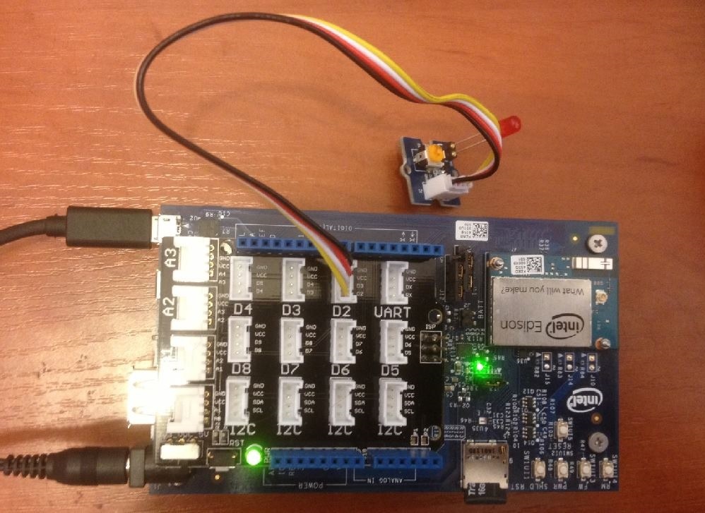
Connection board
I assume that you have already connected the Intel Edison board to a computer via USB or WiFi. If not, then there are several ways. You can enable serial port emulation via USB, this is an extreme microUSB connector. You can enable USB network interface emulation, this is the middle microUSB connector. You can use wifi. Power can be connected via USB or using a power supply.
- Connecting your Intel Edison board using Wi-Fi
- Connecting to your Intel Edison board using Ethernet over USB
- Setting up a serial terminal on a system with Windows
- Setting up a serial terminal with Mac * OS X
- Setting up a serial terminal on a system with Linux
MRAA Library
To simplify the work with sensors from JavaScript there are special libraries. One of them is MRAA. It provides a fairly low level of work with the board.
http://iotdk.intel.com/docs/master/mraa/index.html - MRAA Documentation
Its main task is to set up a pin for input or output, output a zero or one, read the value of a digital or analog signal from a contact. Can configure the pin to work in PWM (PWM) mode and set its parameters. This is enough to blink the LED, read the state of the button, get the temperature value from the sensor, turn on the servo.
Here, for example, the program to enable the on-board LED:
var mraa = require('mraa'); var myOnboardLed = new mraa.Gpio(13); // 13- myOnboardLed.dir(mraa.DIR_OUT); // myOnboardLed.write(1); // But if you need to manage something more complicated, for example, an LCD screen, then this is not enough.
UPM library
The next library is UPM. It provides a higher level of work.
http://iotdk.intel.com/docs/master/upm/node/ - UPM documentation for Node.JS
The library implements algorithms for controlling complex devices, such as screens, servomotors, etc. Otherwise, this would have to be done independently. We will use it to control the LCD screen on the I2C serial bus.
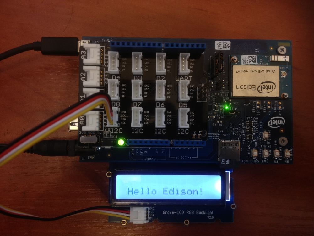
An example of a program that displays text on an LCD screen:
var jsUpmI2cLcd = require ('jsupm_i2clcd'); var lcd = new jsUpmI2cLcd.Jhd1313m1(0, 0x3E, 0x62); lcd.setCursor(1,5); lcd.write('Hello Edison!'); Job Node.JS
When you create an application in Intel XDK on a computer, you upload it to the board (the Upload button). It will be placed in a folder, but will not run. The project is located on the board in the /home/root/.node_app_slot folder. This link is configured from the root / node_app_slot
The application sent to the board can be launched in two ways. Or directly from the development environment with the Run button. Or manually in the console on the board, for this you need to go to the / node_app_slot folder and execute the command
node main.js If you restart the Edison board, the application starts automatically. To prevent this from happening, you can either remove the start of the daemon from the autorun, or remove or rename the main.js file, which is easier.
Now we will look at all the sensors that come with the Grove Starter Kit Plus (Intel IoT Edition) in groups by connection type.
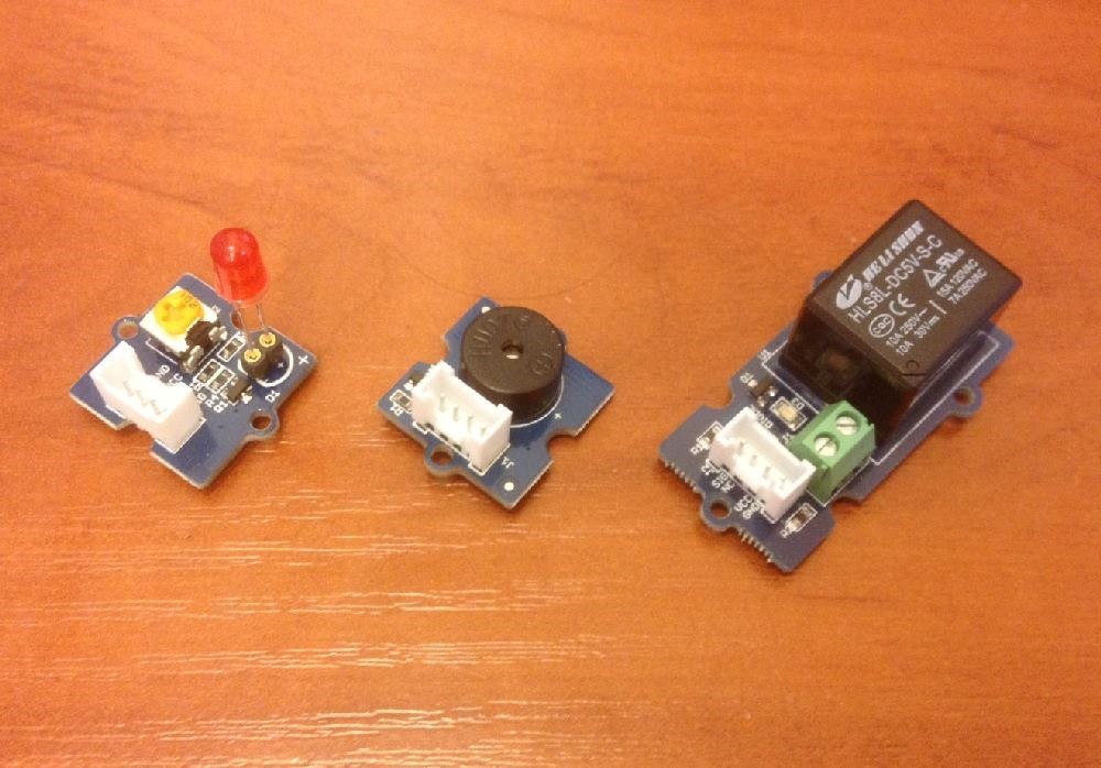
LED, buzzer, relay
All these devices are connected to a digital output. You can use D2-D8. When the unit is fed, they turn on, turn off at zero.
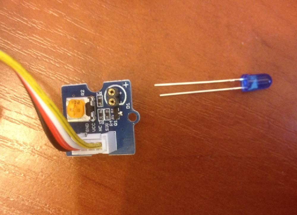
Light-emitting diode
Included are three LEDs - red, blue and green. Choose any. The LED device is polar, so it is important to connect it correctly. It is necessary to insert the LED so that the long leg (anode) is in the slot marked with “+”. But if you connect wrong, it just will not shine.
Connect it to D2 and blink.
Source code main.js
/*jslint node:true, vars:true, bitwise:true, unparam:true */ /*jshint unused:true */ // mraa var mraa = require('mraa'); // D2 var myOnboardLed = new mraa.Gpio(2); // myOnboardLed.dir(mraa.DIR_OUT); var ledState = true; // // 100 setInterval(periodicActivity,100); function periodicActivity() { myOnboardLed.write(ledState?1:0); // ledState = !ledState; // } Buzzer
Buzzer or squeaker. When voltage is applied, it starts beeping at the same frequency. Connects to a digital output. You can use the code as for with the LED.
Relay
A relay is a switch that is controlled by a signal. When a unit is applied, the switch closes the contacts; when applying a zero, it opens. It can be used to control devices that are rated for voltages greater than 5V and currents greater than 0.5A and therefore are connected to an external power source. For example, you can turn on the desk lamp. The relay that comes with Grove has options of 10A x 250V. It is 2.5 kW. But this is the ultimate power. I think the kettle should not be included in this way. And if you switch the device with a supply voltage of 220 V, be careful, firstly, the voltage itself is dangerous to health, and secondly, if it gets onto the board, then it will most likely burn.
PWM and LED brightness control
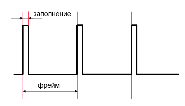
And what if we want to produce an analog signal of the intermediate level, and not just zero and one? Or how to turn on the LED at half brightness, if it has only two states? This can be achieved using PWM - Pulse Width Modulation (PWM - Pulse-width modulation). When used, the signal periodically changes from 1 to 0.
This happens every frame. When the time of both levels is the same, then on average we get a value of 0.5. Suppose the unit was 25% of the time, then the signal is the same, 0.25 of the maximum. If we control the LED like this and the frame is chosen small enough, then due to the inertia of our vision we will see this average brightness value.
Part of the digital connectors on the board can work in PWM mode, on the shield it is D3, D5, D6. (On the Edison board itself, they are labeled with a "~").
To enable PWM you need to set several parameters. The first is the repetition period of the signal, i.e. the frame size. The second parameter is the time during which there will be one. It can be set either as a factor of 0-1, or as a time value in ms.
Here is an example in which the LED will flash, gradually changing its brightness.
Source code main.js
/*jslint node:true, vars:true, bitwise:true, unparam:true */ /*jshint unused:true */ var mraa = require("mraa"); var pwm3 = new mraa.Pwm(5); var frameSize = 2000; pwm3.enable(true); pwm3.period_us(frameSize); var value = 0; var step = 0.04; setInterval(proc, 20); function proc() { value += step; if( value < 0 ) { value = 0; step = -step; } else if( value > 1 ) { value = 1; step = -step; } pwm3.write(value); } The button is normal and touch
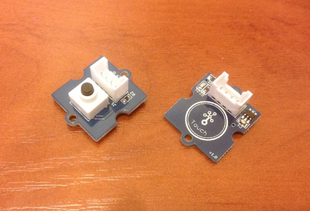
The buttons are connected to the digital inputs D2-D8. Give the unit if they clicked. The difference from each other is that the touch button is a capacitive sensor and therefore triggers from a light touch and works even through a layer of paper.
Create an application that will display the state of the button.
Connect the button to the D8:
Source code main.js
/*jslint node:true, vars:true, bitwise:true, unparam:true */ /*jshint unused:true */ var mraa = require('mraa'); // D8 var myButton = new mraa.Gpio(8); // myButton.dir(mraa.DIR_IN); // getButton(); // 20 function getButton() { var b = myButton.read(); console.log('button='+b); setTimeout(getButton,20); } If, after launching, you press a button, you will see something similar.
Rotation sensor, thermometer, microphone, light sensor
All these sensors produce an analog signal of different levels depending on the external influence on them. Connect to analog inputs A0-A3. The signal value is 0-1023.
Rotation sensor
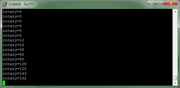
Returns the angle at which it is rotated. Values range from 0-1023.
Connect it to A0.
Source code main.js
/*jslint node:true, vars:true, bitwise:true, unparam:true */ /*jshint unused:true */ var mraa = require('mraa'); //require mraa // A0 var myRotary = new mraa.Aio(0); getRotary(); function getRotary() { var b = myRotary.read(); console.log('rotary='+b); setTimeout(getRotary,20); } When you start the program and rotate the knob, you will see something like this.
temperature sensor
As you can guess, it returns the temperature value. But it is not enough just to count the value, since this will be the relative resistance of the thermistor. To convert to degrees, it is better to use the UPM library. So, let's connect the sensor to A0.
Source code main.js
/*jslint node:true, vars:true, bitwise:true, unparam:true */ /*jshint unused:true */ var mraa = require('mraa'); var groveSensor = require('jsupm_grove'); // A0 var temp = new groveSensor.GroveTemp(0); setInterval(getTemp,100); function getTemp() { var celsius = temp.value(); console.log('temp='+celsius); } The library function returns only an integer value. If you need a more accurate value, you can use the following code, which uses the value directly from the sensor.
Source code main.js
/*jslint node:true, vars:true, bitwise:true, unparam:true */ /*jshint unused:true */ var mraa = require('mraa'); //require mraa var temp = new mraa.Aio(0); setInterval(getTemp,100); function getTemp() { var sens = temp.read(); var celsius = convertTemp(sens); console.log('temp='+celsius); } function convertTemp(sensorValue) { var resistance=(1023-sensorValue)*10000/sensorValue; // var temperature=1/(Math.log(resistance/10000)/3975+1/298.15)-273.15;//convert by datasheet ; return temperature; } Microphone
The microphone produces a sound level. Connect to A1. Values, as usual for an analog input, are in the range from 0 to 1023.
Source code main.js
/*jslint node:true, vars:true, bitwise:true, unparam:true */ /*jshint unused:true */ var mraa = require('mraa'); var myMic = new mraa.Aio(1); getLevel(); function getLevel() { var lev = myMic.read(); console.log('level='+lev); setTimeout(getLevel,20); } Servo
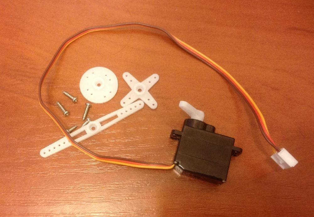
A more interesting thing is the servo drive, this is a motor that turns at a given angle (0-180 degrees) and tries to maintain this position.
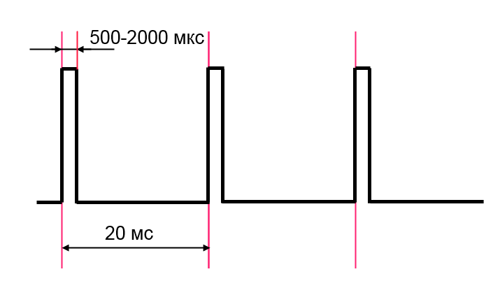
To set the angle, it is necessary to apply a pulse of a certain duration (duty cycle). Such impulses must come constantly, usually 50 times per second (20 ms). But the period of arrival is not so important, the duration is important. It can be from 500 μs to 2000 μs. With a minimum pulse value, an angle of 0 degrees is established, with a maximum of 180 degrees.
For different servo drives, the pulse widths may vary. They can be selected experimentally. But you have to be careful. If the duration value is outside the allowable range, then the servomotor starts to knock and heats up very much. Immediately disconnect it from the connector! When working properly, it should turn to a given angle, stop and shut up, while remaining cold.
We will use a digital output that can output a PWM signal. These are pins D3, D5, D6.
It should be noted that due to the fact that PWM can only accept 256 values as an input and it’s impossible to use all the values for filling, but only a small part, it turns out that the servo does not have many fixed angles, I got about 20.
Source code main.js
var mraa = require('mraa'); // var frameSize = 20000; // D3 var pwm3 = new mraa.Pwm(3); pwm3.enable(true); pwm3.period_us(frameSize); // var minServoTime = 420; // var maxServoTime = 2000; // 0-1 var value = 0.5;// , 90 // var servoVal = Math.floor(minServoTime + (maxServoTime - minServoTime) * (1-value)); pwm3.pulsewidth_us(servoVal); LCD screen
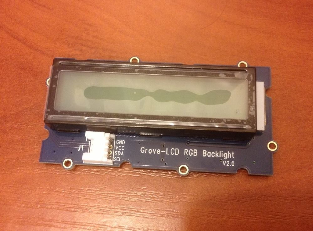
The screen is more complex than the LED, so it connects to a special I2C serial bus.
The screen can display text in 2 lines of 16 characters each. There are RGB lights. The documentation says that it supports English and Japanese, and there is the ability to add a certain number of its characters.
Since the devices are connected to the I2C bus in parallel, all the connectors on the board are equivalent, and the screen can be inserted into any of them.
We use the UPM library.
http://iotdk.intel.com/docs/master/upm/node/classes/jhd1313m1.html - work with this screen.
var jsUpmI2cLcd = require ('jsupm_i2clcd'); var lcd = new jsUpmI2cLcd.Jhd1313m1(0, 0x3E, 0x62); lcd.setColor(100, 127, 53); lcd.setCursor(1,1); lcd.write('Hello Edison!'); Putting it all together
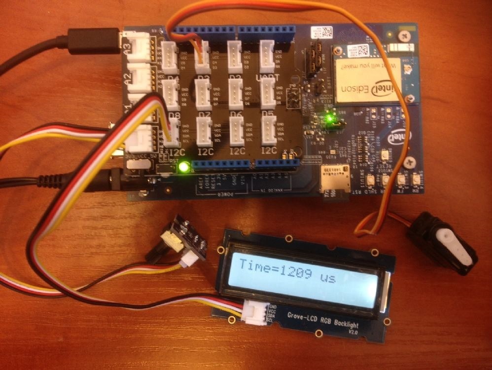
So we looked at all the devices that are in the Grove Starter Kit Plus. Let's try to collect something more interesting that simultaneously uses several modules.
We will have a rotation sensor (A0), during rotation of which the servo (D3) will turn to the appropriate angle. The found pulse width of the PWM to rotate at this angle will be displayed on the LCD screen (I2C).
Source code main.js
/*jslint node:true, vars:true, bitwise:true, unparam:true */ /*jshint unused:true */ var mraa = require('mraa'); var jsUpmI2cLcd = require ('jsupm_i2clcd'); var lcd = new jsUpmI2cLcd.Jhd1313m1(0, 0x3E, 0x62); lcd.setColor(100, 127, 53); var myRotary = new mraa.Aio(0); var pwm3 = new mraa.Pwm(3); pwm3.enable(true); var frameSize = 20000; pwm3.period_us(frameSize); setInterval(proc, 100); function proc() { // var maxRotary = 1023; var valueRate = value / maxRotary ; // var minServoTime = 420; var maxServoTime = 2000; var servoVal = Math.floor(minServoTime + (maxServoTime - minServoTime)*valueRate); // pwm3.pulsewidth_us(servoVal); // lcd.setCursor(0,0); lcd.write('Time=' + servoVal + ' us '); } Creating a web server
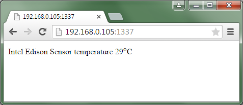
Since we are considering developing for IoT (Internet of Things), we need to make it possible to work with the device via the Internet. The following example creates a web server that displays the current temperature on a temperature sensor. The server listens to port 1337 and responds to the request to the site root. The temperature sensor is connected to A0. If your card has an address of 192.168.0.105, then in the browser indicate 192.168.0.105:1337.
Source code main.js
var mraa = require('mraa'); var groveSensor = require('jsupm_grove'); var temp = new groveSensor.GroveTemp(0); var lastSetVal = 0; var app = require('express')(); var http = require('http').Server(app); var url = require("url"); var numCalls = 0; app.get('', function (req, res) { 'use strict'; res.writeHead(200, {"Content-Type": "text/html"}); res.write('Intel Edison Sensor temperature ' + temp.value() + '<sup>o</sup>C'); res.end(); }); http.listen(1337, function () { 'use strict'; console.log('listening on *:1337'); }); Work example:
Dessert - browser control
So, promised at the very beginning. Create a device controlled via a browser with an arrow on the servo and a screen. And with each turn command from the client, it will return the actual set value in JSON format, since no turn occurs in the extreme positions. And as a small bonus, you can send text to the connected LCD screen.
The program consists of two parts. One of them is on the Edison device. This is a web server, main.js file. It responds to requests from the client, servicing the servo and screen. Uses the library express and http.
The second part is on the client in the browser. It receives commands from the user and sends them to the server. Receives data from a web server in JSON format and displays it. Uses jQuery library.
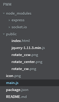
This application will be a little more complicated. In the project, create a public folder, put static content in it. In our case, these are three images for the buttons - rotate_ccw.png, rotate_cw.png, rotate_center.png, html-file index.html, which is displayed in the client’s browser and the jquery-1.11.3.min.js library (It will need to be downloaded from official website jquery.com/download )
On the client, the script monitors clicking on the images of arrows and when such an event occurs, sends a request to the server at the corresponding address / right, / left, / center and waits to receive JSON data with information about the position of the arrow. When you click on the "Set text" button, the text from the input field is sent to the server.
Contents of the index.html file
<html><body> <title>Rotation</title> <script src="jquery-1.11.3.min.js"></script> <script> function showVal(val) { $("#val").text('Value='+val); } function left() { $.getJSON( "/left", function( data ) { showVal(data['value']); } ) ; } function right() { $.getJSON( "/right", function( data ) { showVal(data['value']); } ); } function center() { $.getJSON( "/center", function( data ) { showVal(data['value']); } ); } function setText() { $.get("/text/"+$("#text").val()); } </script> <a onclick="left();"> <img src="rotate_ccw.png"/> </a> <a onclick="center();"> <img src="rotate_center.png"/> </a> <a onclick="right();"> <img src="rotate_cw.png"/> </a> <br/> <h1 id="val">Value=0</h1> <input id="text" type="text" name="data" value=""> <input type="submit" value="Set text" onclick="setText();" /> </body></html> On the board, the screen is connected to I2C. Servo connects to D3. The server listens to port 1337. The application is waiting for the appeal to / right. With such a request, if possible, it is rotated to the right and a JSON response is sent with information about the position of the arrow. An appeal to / left and / center is handled similarly. If you type / text / abcdef, the string abcdef will be displayed on the LCD screen. Work with the servo and the screen was discussed earlier.
Main.js content
var mraa = require('mraa'); //----- PWM ----- var value = 0.5; var step = 0.05; var frameSize = 20000; var pwm3 = new mraa.Pwm(3); pwm3.enable(true); pwm3.period_us(frameSize); setTime(value); //---------- LCD ---------- var jsUpmI2cLcd = require ('jsupm_i2clcd'); var lcd = new jsUpmI2cLcd.Jhd1313m1(0, 0x3E, 0x62); var express = require('express'); var http = require('http'); var app = express(); // app.use(express.static(__dirname + '/public')); // app.get('/left', function (req, res) { value = fitValue(value-step); setServoValue(res,value); }); // app.get('/right', function (req, res) { value = fitValue(value+step); setServoValue(res,value); }); // app.get('/center', function (req, res) { value = 0.5; setServoValue(res,value); }); // LCD app.get('/text/:text', function (req, res) { var text = req.params.text; var t = text.toString().substring(0, 16); var vs = t + ' '.substring(0,16-t.length); lcd.setCursor(0,0); lcd.write(vs); console.log('value='+vs+'='); res.writeHead(200, {"Content-Type": "text/html"}); res.end(); }); // http.createServer(app).listen(1337); // JSON function setServoValue(res,v) { res.writeHead(200, {"Content-Type": "text/json"}); var text = '{"value":"'+value.toFixed(2)+'"}'; res.write(text); console.log(text); setTime(value); res.end(); } // function setTime(valueRate) { var minServoTime = 420; var maxServoTime = 2000; var servoVal = Math.floor(minServoTime + (maxServoTime - minServoTime)*(1-valueRate)); pwm3.pulsewidth_us(servoVal); } // function fitValue(v) { if( v > 1 ) { v = 1; } if( v < 0 ) { v = 0; } return v; } Package.json Contents
{ "name": "PWM", "description": "", "version": "0.0.0", "main": "main.js", "engines": { "node": ">=0.10.0" }, "dependencies": { "express" : "latest", "http" : "latest" } } Image rotate_ccw.png
Image rotate_cw.png
Image rotate_center.png
That's all. We start and check.
Demons Node.JS
A few words about how demons work on the Intel Edison board.
The system is running the xdk-daemon daemon. If you stop it with the command:
systemctl stop xdk-daemon then the running Node.JS application will stop. You can restart it with the command:
systemctl start xdk-daemon or restart:
systemctl restart xdk-daemon The program can be edited directly on the board (vi), just do not forget to restart it after the change. Either way:
systemctl restart xdk-daemon Or, if the program was launched in the console via the command:
cd /node_app_slot node main.js then you can stop it through <Ctrl> + <C>
Useful
» Play audio on Intel Edison via Bluetooth using the Advanced Audio Distribution Profile (A2DP)
Installing OpenCV 3.0.0-rc1 (using IPP and TBB) on Intel Edison Yocto. USB camera in OpenCV
» Use the Intel Edison board to change the color of the Orbotix Sphero ball when new tweets appear
» Connect to Intel Edison via Android with Bluetooth LE (BLE)
Source: https://habr.com/ru/post/260259/
All Articles