When does not help the DAC. Digital potentiometers in detail. Part one
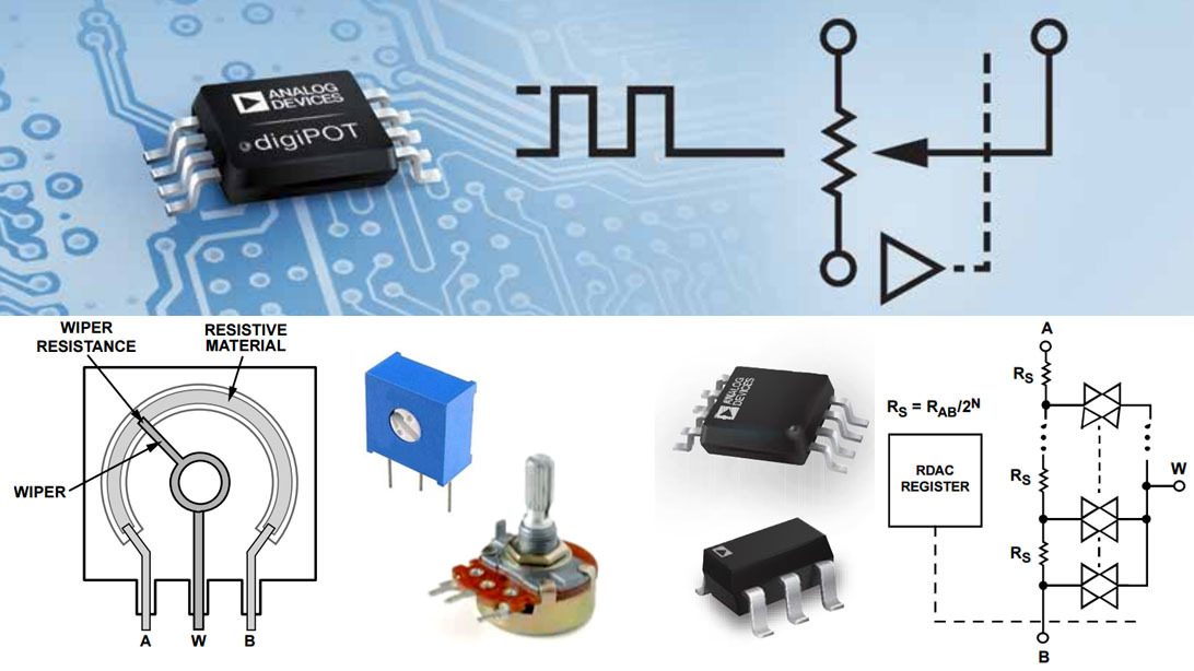
Progress has not bypassed not only the bike. Today, traditional variable and trimming resistors in very many applications give way to digital resistances. In English language sources, they are called digital potentiometer, RDAC or digiPOT. The scope of these devices is much wider than adjusting the sound level. In particular, they come to the rescue in so many cases when it is necessary to change the parameters of the feedback, which is difficult to implement with the help of traditional DACs.
Especially effective is their use in conjunction with operational amplifiers. So you can get adjustable amplifier stages, converters of various kinds of quantities, filters, integrators, voltage and current sources and much more. In short, these very inexpensive and compact devices can be useful to every electronics developer and amateur radio ...
')
Initially, I wanted to write a short article, but as a result of in-depth study of the topic, the material hardly fit in two parts. Today I will try to talk about the architecture of these devices, their capabilities, limitations of use and development trends. In conclusion, I will touch upon the topic of application areas in passing, since specific examples of practical implementation of schemes based on them will be discussed in the second part. Many examples!
Personally, over the past five years I have successfully applied digital resistances in several of my developments, I hope that this series of articles will be useful for many and will help you solve many problems more elegantly and simply than today. For people who are far from the development of electronics, this article can simply broaden their horizons, showing how even the simplest things like variable resistors evolve under the onslaught of digital technology.
PS So it turned out that another article from this series has already been published and there is only one example in it, but it has been analyzed in detail. For the rest of the promised examples will have to write a third.
Architecture.
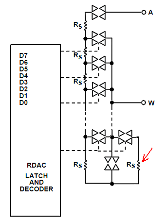
In order to understand how this device works, let's turn to the functional diagram. It shows the analog part of the digital 8 bit resistance.
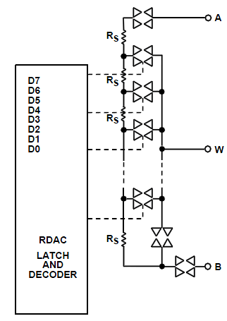
The basis of the device is 255 resistors of the same rating and bi-directional electronic switches made using CMOS technology. The digital value in the interval 0-255 is written to the register from which it is fed to the decoder. Depending on the value stored in the register, one of the keys is triggered, connecting the middle pin W to the selected point in the linear resistance matrix Rs. Two more keys are used to connect the extreme terminals A and B. With their help, the device can go into inactive mode.
Conclusions A and B are analogs of extreme conclusions of variable resistance, W is an average output to which the slider is attached to ordinary variable resistors.
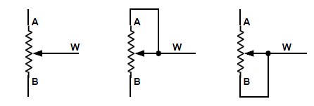
Possible wiring diagrams are also similar to traditional variable resistances ...
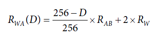
Consider how to set the desired resistance for example 10 kilohm resistor. To begin with, we will calculate the value of each of the resistors of the assembly required for the formation of such resistance Rs = 10,000 / 256 = 39.06 Ohm. Suppose we are trying to regulate the resistance between the terminals W and B. To obtain zero, we write this value in the control register, but instead of the desired zero we get a resistance of 100 Ohms. Why? The fact is that each of the device’s contacts has its own internal resistance and in this case it is 50 Ohms, therefore the minimum value that can be obtained with this potentiometer is not zero, but one hundred Ohms - the resistance of contacts W and B. register unit we get 50 + 50 + 39 = 139 Ohms.
In the general case, the resistance between the terminals W and B can be calculated depending on the value of the register D by the formula:
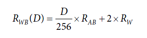
Where:
- D - register value from 0 to 255
- Rab - nominal resistance
- Rw - resistance of one contact
It is not difficult to guess that the resistance between the terminals W and A is calculated as
Connection Interfaces
We now consider the functional diagram of the entire device that has an I2C interface.
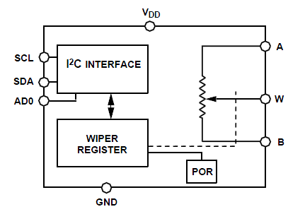
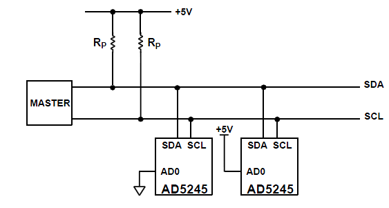
Here some issues can only be caused by the output of AD0. It is designed to be able to simultaneously use two potentiometers in one I2C channel. Depending on whether there is a logical zero or one on it, the address of the device on the I2C bus changes. Wiring diagram of two chips on one bus is shown below.
In addition to the I2C interface, the SPI interface is often used to control these devices. In this case, it is also possible to control multiple devices on a single bus. To do this, they are combined in a chain. For example:
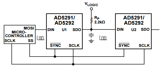
In this mode, the buffer register for writing values works as a shift. Each new bit enters the DIN input and over the strobe with SCLK is recorded in its lower order. At the same time, the high-order bit goes out through the SDO pin and goes to the next device in the chain. After the information is recorded in all devices, a SYNC gating pulse is received, according to which the new register values of all devices in the chain are rewritten from the buffer to the working register. The obvious disadvantage of this solution is that there is no way to write information into a single device. For any change in values, it is necessary to update the contents of the registers in the entire chain.
To solve this kind of problems, as well as to save the final price, solutions are manufactured by microcircuits, including two, four, and even 6 digital resistances simultaneously.
Operating voltage and current
Perhaps the most significant drawback of the first development was the limited voltage allowed on the terminals. It should not exceed the supply voltage which could lie in the range from 2.7 to 5.5V, and most importantly could not go into the negative region, because of which the use of microcircuits was limited to devices with unipolar power. First of all, the engineers solved the problem of bipolarity. So there appeared devices capable of operating from both unipolar voltage up to 5.5 Volt and supporting bipolar power up to ± 2.75V. Then versions with a maximum supply of ± 5.5 and even ± 16.5 (up to 33 volts unipolar in AD5291 / 5292) began to appear. Of course, traditional resistances still benefit greatly in this parameter, but for the vast majority of circuits, 33 volts is enough.
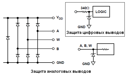
However, whatever the maximum voltage the device supports, if there is a possibility of its overshooting, it is necessary to apply at least the simplest protection with the help of diodes or suppressors.
Another serious problem is the low maximum operating current of digital resistances, which is primarily due to their small size. Without the risk of degradation over time, the average direct current for most models should not exceed 3 mA. If the flowing current has a pulsed character, its maximum value can be higher.
Fight for accuracy. Technology controlled chaos
Unfortunately, the existing manufacturing technology allows for the possibility of deviation of the resistance of the integral resistors used in digital resistances, up to 20 percent of the nominal. However, within the same batch and the more so one specific device, the resistance difference does not exceed 0.1%. In order to improve the accuracy of the installation, the manufacturer began to measure the resistance of resistors on at least each plate and to register in the non-volatile memory of each of the microcircuits not the nominal, but the real resistance, which turned out during production, with an accuracy of 0.01 percent. Such a mechanism allows, in particular, in the AD5229 / 5235 microcircuits, to calculate the real accuracy of the resistance setting with an error unattainable even in multi-turn trimming resistors - 0.01 percent. Based on this, you can correct the operation of decoding a digital code into a resistance. Suppose the elementary impedance is 100 ohms. Then, in order to set the resistance in 1K, you set the digital register to 10. But if in a real device the resistance has a big deviation from the nominal and is 110 Ohm, then at level 10 you will get 1.1K. However, considering the actual value of the resistance, the microcontroller can recalculate the code and actually sends the code 9 to the decoder instead of ten. Then in reality we get 9 * 110 = 990 Ohm.
In addition, AD has patented a technology for calibrating resistance values with an accuracy of 1%. Unfortunately, I could not find the information what is its mechanism of work.
To increase the discreteness of the installation of resistance devices with a 10-bit decoder were developed, providing 1024 steps of adjustment. A further increase in this parameter can be achieved using a series or parallel connection of two digital resistances with different ratings.
Temperature stability
It's not bad at all. The use of resistors manufactured using film technology allows to achieve a drift level not exceeding 35ppm / ° C (0.0035%). There are devices with thermal compensation, the temperature drift of which is at the level of 10ppm / ° C. In this parameter, digital resistance is superior to many engine analogs. For applications in which this parameter is not relevant, you can choose cheaper devices with semiconductor resistors whose drift is at 600 ppm / ° C.
The operating temperature range of most devices from ADI ranges from -40 ° C to + 125 ° C, which is sufficient for the vast majority of applications.
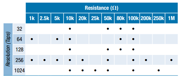
A number of resistances available.
Of course, there is no such diversity as traditional slider resistors, however there is something to choose from. The table below illustrates the dependence of the available resistances on the width of the device.
Signal distortion
The main distortion of the signal introduced by digital amplifiers can be divided into two classes.
- Harmonic distortion or Western style total harmonic distortion (THD).
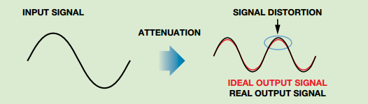
These distortions increase with increasing applied voltage. You can get an idea of their typical values from the following table compiled for the AD9252 ...
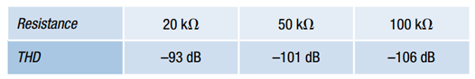
In some cases, this type of distortion may increase to -60 dB
- Distortion caused by non-linearity of the frequency response.
Contact pads, electronic keys and elementary resistances themselves have a finite parasitic capacity. As a result, digital resistances are a kind of low-pass filter and at high frequencies their resistance to the signal increases.
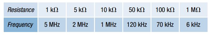
The effect of this effect increases with increasing resistance of the device. The table below shows at what frequency there is a signal attenuation of 3 dB for different resistances of different denominations.
For greater clarity, let me give you more graphs of signal transmission depending on the set resistance level for AD5291 microcircuits with different face values of 20 and 100 kilo.
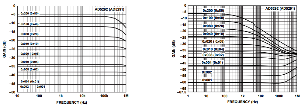
Thus, it turns out that the higher the resistance value, the lower its operating frequency.
"Fishechki" evolution
Manufacturers are trying to make work with the device more comfortable, inventing various pleasant things. As a result, digital resistances have acquired an internal non-volatile memory, both once and repeatedly programmable.
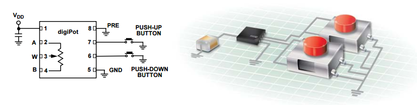
Its main purpose is to store the initial resistance value, which is automatically set immediately after the power is turned on. The first models of electronic resistors were installed when power was applied to the middle position, then an additional leg appeared to reset to zero, then the level could be set using the value stored in the memory. In the most advanced models, several preset values can be written into memory, between which the user can then quickly switch by pressing buttons.
Speaking of buttons - in some models they added two buttons for incremental increase / decrease of resistance.
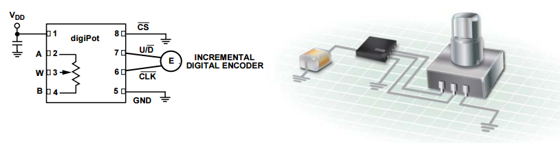
In addition, an interface for connecting encoders.
What else to improve?
You can dream up in which direction progress will be made in the production of digital resistances.
To achieve greater accuracy, the switching system may change.
For example, adding to the traditional circuit only one resistance in parallel connection, well, well, two. Another one in the upper arm for symmetry - you can double the resistance setting accuracy! The combination of two devices in one case will give the opportunity to increase the discreteness and accuracy several times.
Introduction to the case of the simplest microcontroller controlling the decoder will, based on the actual value of the resistances obtained, create a switching program for setting the resistance of the device with very high accuracy - 0.1% and higher. By integrating a temperature sensor into such devices, compensation can be introduced to maintain linearity over a very wide temperature range. The emergence of analogs of frequency-compensated resistances for HiFi equipment, which will be several resistances in one package, is possible. One of them will be used to adjust the volume, and the other for frequency compensation.
Areas of use
I will cite specific circuit solutions based on digital resistances in the next part of the article, for now, just consider the areas of application.
Of course, amplifiers with adjustable gain first come to mind.
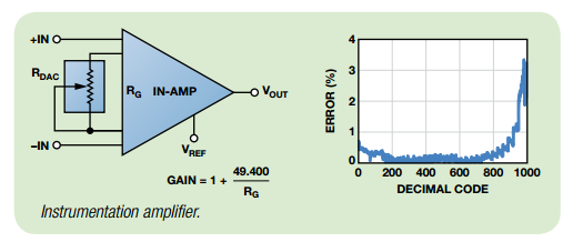
As a result of increasing the accuracy of setting the values, it became possible to use electronic resistances in the control circuits of the gain level of instrumentation amplifiers.
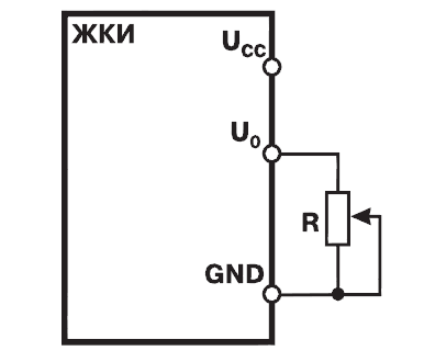
Automatic or software changes to the contrast of the liquid crystal display can be organized using electronic resistance of 10 Kilo.
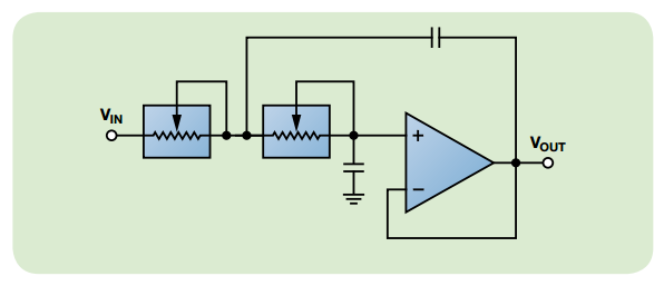
Based on digital impedances, it is easy to implement controlled filters. High-order filters often require several equal resistors in several inputs. This is very convenient to implement using instruments containing several resistances in the same package, since in this case we get excellent repeatability. The figure shows a simplified scheme of the simplest controlled low-pass filter.
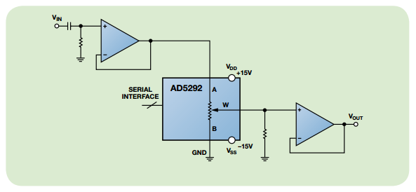
A logarithmic amplifier, with a relatively high supply voltage, based on the AD5292.
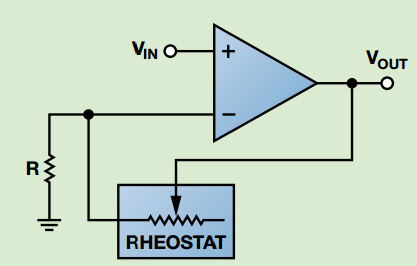
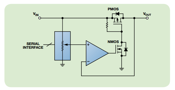
Software controlled voltage regulator.
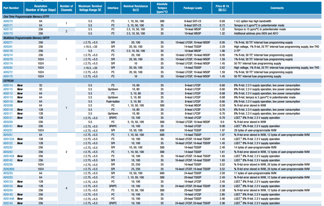
ADI Linear Series
In conclusion, I will provide a complete list of electronic potentiometers available today from Analog Devices. It should be noted that such devices produces not only this company. For example, MAXIM has also been making good chips for a long time.
To begin with, devices that do not support user programming.
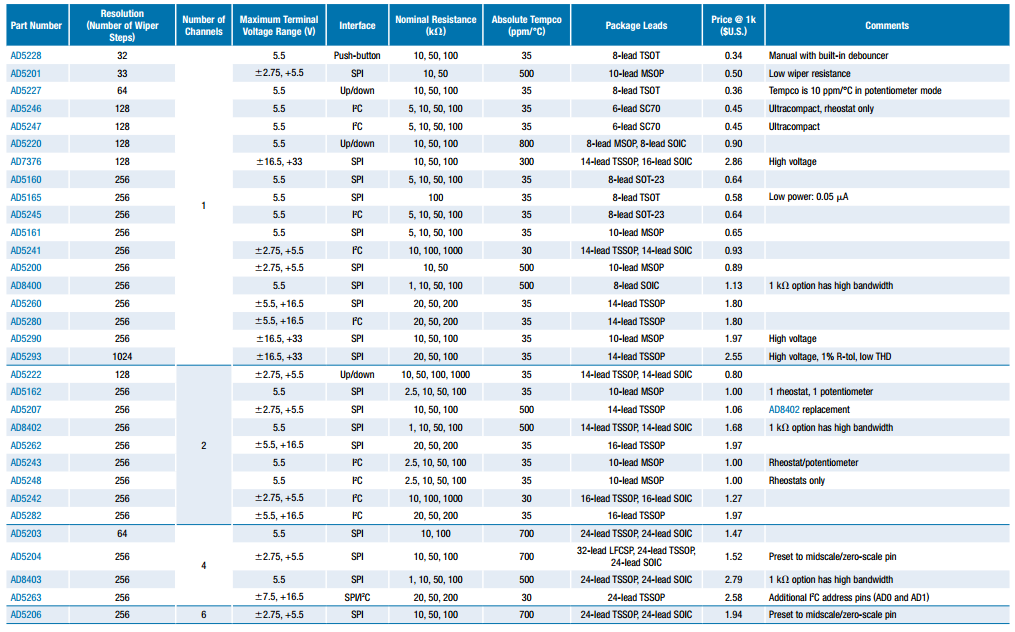
Finally, programmable devices. When choosing a particular model, it is worth paying attention to the fact that they are both programmable once and those that support reprogramming. Moreover, a large number of cycles provide only microcircuits with a memory made by EEPROM technology.
This concludes the review. The next article will be devoted to the consideration of practical schemes with the use of digital resistances.
PS It so happened that another article from this series has already been published and there is only one example in it, but it has been analyzed in detail. For the rest of the promised examples will have to write a third.
Source: https://habr.com/ru/post/260233/
All Articles