Zoning for cluster storage in pictures
NetApp FAS storage systems can cluster into up to 8 nodes to provide access to SAN networks and up to 24 nodes for Ethernet networks. Let's look at an example of setting up zoning and a wiring diagram for such cluster systems.
General connection diagram for SAN and NAS.
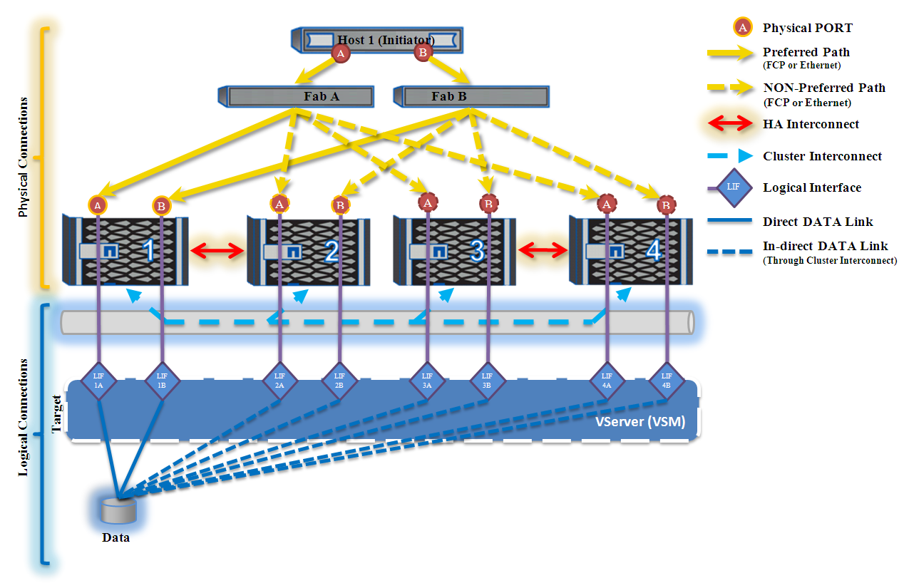
So, consider connecting one host to a 4 node cluster (2 HA pairs). Here the classical connection scheme with fault tolerance each to each with duplication of paths and network switches is applied. Recommendations for building a host and storage to achieve high performance can be found in the corresponding articles Windows / Linux / VMware ESXi with NetApp FAS .
It is worth noting that, only two ways, in this scheme, will be optimal for data access, more details here . However, all the paths to this data must be workable. Thus, both zoning and VLAN settings must be configured so that there is always access to the data, if it is migrated to another node of the cluster (including beyond the HA pair).
')
Following the recommendations of NetApp, the zoning scheme for our example will be simple - one zone for one initiator port address (on the Host): one on switch A and another on switch B. Each such zone will have one initiator address connected to the factory and all the target addresses, connected to the same factory (at least 2 target addresses). Examples of zones:
On switch A, the “Host_1-A-Port_A” zone consists of the following WWPNs:
On switch B, the Host_1-B-Port_B zone consists of the following WWPNs:
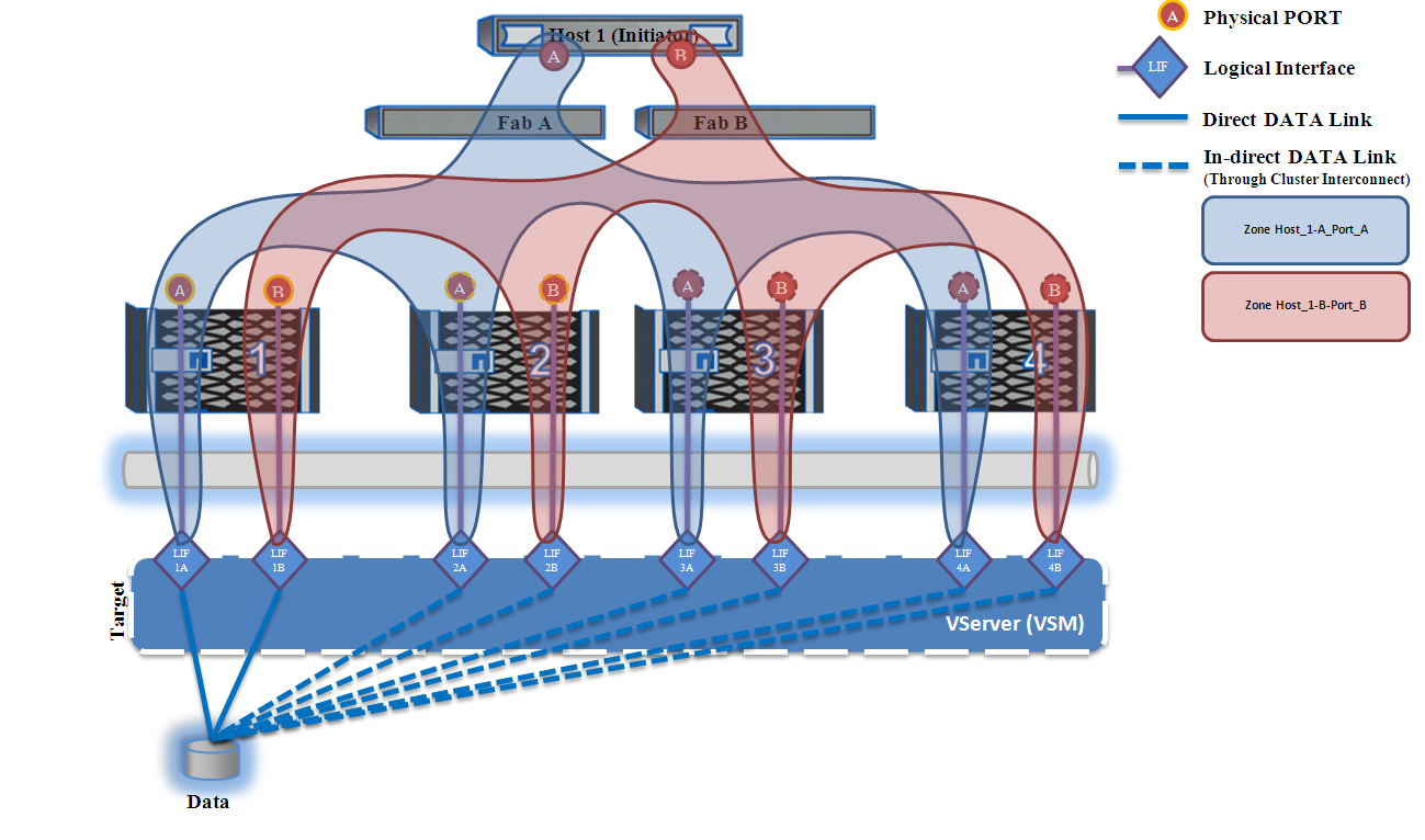
SAN zoning scheme.
VSM is a virtual machine that lives on all the nodes of the storage cluster. Data that is served by such a virtual storage system can migrate online to the nodes of the cluster, migration occurs via Cluster Interconnect ports. In the case of a SAN network using the ALUA mechanism, the preferred paths automatically switch after LUN.
Each Vserver has its own WWNN , it is one for the entire cluster, so for the host the entire cluster is presented as one device.
One physical interface can be used by several servers, i.e. multiple LIF interfaces can live on the same physical port. The LIF interface is bound “on top of the physical” port and has its own “virtual” WWPN . When configuring the storage system, make sure that at least one LIF interface is configured on the node where the LUN is located, so that it can be used as the preferred data path. To be able to address multiple WWPN addresses behind a single physical port, you must activate the NPIV feature on the switch.
For both cDOT 8.x and 7-Mode 7.3 / 8.x : Netap recommends , for one zone, having one initiator port address (eliminates cross talk between initiators) and the smallest required number of targets, which reduces the number of target polls in search of the moon ( at least 2 target addresses). It is also recommended to use zoning using World Wide Port Name addresses . In the case of cDOT, you can only use soft zoning using World Wide Port Name addresses .
For cDOT 8.x : Please note that the zoning and mapping to the target is not performed on WWPN addresses from physical ports ( 5 0: 0a: 09: 8 X: XX: XX: XX: XX according to NAA 5 , example 5 0: 0a : 09: 8 2: 86: 57: d5: 58), which will also be visible on the switch ports. When zoning and mapping use "virtual" WWPN addresses from LIF interfaces ( 2 X: XX: 00: a0: 98 : XX: XX: XX according to NAA 2 , example 2 0:00: 00: a0: 98 : 03: a4 : 6e). The addresses of physical ports are not used at all in cDOT, either in zoning or on hosts.
Learn more about how to configure NetApp FD cDOT for SAN network .
Comments on errors and suggestions for changes in the text please send to the LAN .
General connection diagram for SAN and NAS.
So, consider connecting one host to a 4 node cluster (2 HA pairs). Here the classical connection scheme with fault tolerance each to each with duplication of paths and network switches is applied. Recommendations for building a host and storage to achieve high performance can be found in the corresponding articles Windows / Linux / VMware ESXi with NetApp FAS .
It is worth noting that, only two ways, in this scheme, will be optimal for data access, more details here . However, all the paths to this data must be workable. Thus, both zoning and VLAN settings must be configured so that there is always access to the data, if it is migrated to another node of the cluster (including beyond the HA pair).
')
Following the recommendations of NetApp, the zoning scheme for our example will be simple - one zone for one initiator port address (on the Host): one on switch A and another on switch B. Each such zone will have one initiator address connected to the factory and all the target addresses, connected to the same factory (at least 2 target addresses). Examples of zones:
On switch A, the “Host_1-A-Port_A” zone consists of the following WWPNs:
| Node | Port | WWPN |
|---|---|---|
| Host 1 | Port a | Port a |
| NetApp 1 | Port a | LIF-1A |
| NetApp 2 | Port a | LIF-2A |
| NetApp 3 | Port a | LIF-3A |
| NetApp 4 | Port a | LIF-4A |
On switch B, the Host_1-B-Port_B zone consists of the following WWPNs:
| Node | Port | WWPN |
|---|---|---|
| Host 1 | Port b | Port b |
| NetApp 1 | Port b | LIF-1B |
| NetApp 2 | Port b | LIF-2B |
| NetApp 3 | Port b | LIF-3B |
| NetApp 4 | Port b | LIF-4B |
SAN zoning scheme.
VServer or VSM
VSM is a virtual machine that lives on all the nodes of the storage cluster. Data that is served by such a virtual storage system can migrate online to the nodes of the cluster, migration occurs via Cluster Interconnect ports. In the case of a SAN network using the ALUA mechanism, the preferred paths automatically switch after LUN.
Each Vserver has its own WWNN , it is one for the entire cluster, so for the host the entire cluster is presented as one device.
Logical Interface (LIF)
One physical interface can be used by several servers, i.e. multiple LIF interfaces can live on the same physical port. The LIF interface is bound “on top of the physical” port and has its own “virtual” WWPN . When configuring the storage system, make sure that at least one LIF interface is configured on the node where the LUN is located, so that it can be used as the preferred data path. To be able to address multiple WWPN addresses behind a single physical port, you must activate the NPIV feature on the switch.
Zoning Recommendations
For both cDOT 8.x and 7-Mode 7.3 / 8.x : Netap recommends , for one zone, having one initiator port address (eliminates cross talk between initiators) and the smallest required number of targets, which reduces the number of target polls in search of the moon ( at least 2 target addresses). It is also recommended to use zoning using World Wide Port Name addresses . In the case of cDOT, you can only use soft zoning using World Wide Port Name addresses .
For cDOT 8.x : Please note that the zoning and mapping to the target is not performed on WWPN addresses from physical ports ( 5 0: 0a: 09: 8 X: XX: XX: XX: XX according to NAA 5 , example 5 0: 0a : 09: 8 2: 86: 57: d5: 58), which will also be visible on the switch ports. When zoning and mapping use "virtual" WWPN addresses from LIF interfaces ( 2 X: XX: 00: a0: 98 : XX: XX: XX according to NAA 2 , example 2 0:00: 00: a0: 98 : 03: a4 : 6e). The addresses of physical ports are not used at all in cDOT, either in zoning or on hosts.
Learn more about how to configure NetApp FD cDOT for SAN network .
Comments on errors and suggestions for changes in the text please send to the LAN .
Source: https://habr.com/ru/post/260107/
All Articles