USB adapter for a B7-28 digital voltmeter based on Arduino Mega

Our laboratory is engaged in, among other things, measuring the electrical resistance of various samples. The main workhorses of our measurement setup are digital multimeters from the American company Agilent, such as 34401A.
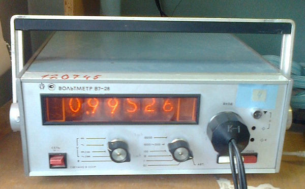
In addition, for a long time there were unused several old but working voltmeters B7-28 (one of them in the photo). This voltmeter, however, is inferior in accuracy and speed to "Americans", but still good enough: accuracy up to 5 decimal digits, acceptable noise, shielded inputs, and most importantly - the possibility of remote control from a PC (which is now called PC).
')
It was impossible to use them for the following reasons:
- Non-standard hardware interface: on the rear panel there are two connectors with 56 and 22 contacts, through which the B7-28 receives commands and returns measurement results. It is impossible to directly connect a voltmeter to a PC;
- Lack of software interface, that is, some system of control commands. You need to turn on the DC voltage measurement mode - if you please, send the appropriate combination of digital levels to the control connector. You need to read the readings - at your service there are 21 digital signals at the CPU socket, and so on.
At the same time, the software of the measurement setup, written and debugged, uses SCPI commands to control voltmeters, and it would be too difficult to introduce support for non-standard interfaces there.
Thus, the task has been reduced to two points:
- Provide the B7-28 with some modern hardware interface to connect it directly to the PC;
- "Teach" him to understand the team SCPI, so as not to touch high-level software.
Why Arduino Mega?
We do not have full-time "electronics engineers" who could develop and solder a microcontroller board, so you had to choose something ready, and the Arduino turned out to be what you need. I will not list its well-known advantages, but it came to us because it allowed us to minimize the amount of soldering and do without special programmers.
Of the entire “Arduin” family, only the Arduino Mega 2560 came up to us: only it had a sufficient number of digital inputs and outputs. The fee is quite expensive, in the Russian online stores the Italian original costs about 4 thousand rubles (at the time of this writing). Fortunately, there are many Chinese counterparts for $ 10 and even lower.
Communication with the PC at the Arduino is carried out via the USB interface, and this solved the problem number 1. It remains to develop a firmware that would implement a subset of SCPI commands and their translation into control signals for B7-28.
Firmware implementation
As a starting point, we used the wonderful
scpi-parser library, kindly written by a colleague from the Czech Republic. This library undertook all the “dirty work” associated with parsing SCPI commands, which saved us up to 6 man-months.The heart of the firmware is the
scpi-multimeter , which implements the SCPI command logic and the state machine that asynchronously reads and processes the voltmeter readings. The library abstracts from the hardware, delegating work with I / O ports to the outside, for which it uses some abstract program interface. This allows you to use the library with almost any type of microprocessor and voltmeter.And finally, the firmware itself is a
v7-28-arduino . This is a small scpi-multimeter code that implements the abstract interface of the scpi-multimeter , that is, it actually writes and reads to the digital and serial ports on the microcontroller board.Soldering

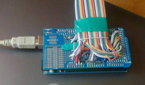
Of course, we didn’t manage to do completely without soldering, but the amount of work turned out to be rather small:
- take a circuit board compatible with the Arduino Mega on the location of the contact holes;
- unsolder pin connectors for mounting on the microcontroller board on the circuit board;
- connect a circuit board with B7-28 connectors with two 30-wire cables;
- Finally, plugging the circuit board into the microcontroller: due to the large number of pin contacts, this is not so easy.

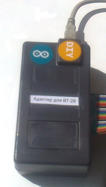
The result is visible in the photos. To protect the solder from mechanical damage and “razbaltyvaniya”, we placed the microcontrollers with installed circuit boards in the “brand” boxes. As a result, our adapter has acquired, albeit not a factory, but rather a decent look.
Adapter test
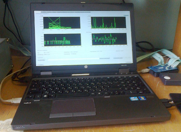
Omit the description of the long process of testing and debugging firmware. When, finally, everything was finished, we decided to connect the B7-28 with the Agilent 34401A to a single measurement setup. As mentioned above, high-level software controls voltmeters through SCPI commands. In the program settings, we specified the virtual COM port corresponding to the microcontroller and:

The program has earned! Now we have more voltmeters and we can simultaneously measure more samples. PROFIT!
Conclusion
Who besides us may be interested in this work?
First of all, these are, of course, the proud owners of the B7-28, who have the opportunity, for moderate means, to supply their voltmeters with an adapter, which allows them to be used as easily as modern analogs. The USB interface is now equipped with any PC, and the out-of-box SCPI command language understands LabVIEW and similar development tools.
Secondly, as mentioned above, the main part of the library does not depend on a particular brand of voltmeter or microcontroller. For example, it is enough just to modify the firmware to support other types of voltmeters, for example, B7-34A.
We invite all interested persons to the project 's source page , there is also a link to ready-made binary builds and documentation.
Thanks for attention!
Source: https://habr.com/ru/post/259919/
All Articles