Fuel level sensor (FLS). Assembly, schemes, production
Greetings dear readers! For several years in a row I wrote on the topic of our service of monitoring vehicles , about the equipment we produce , opening up the internal aspects of production and work as a whole. In this article I want to talk about the complete production cycle of such a very important element of the GPS monitoring and control systems, as the fuel level sensor (search engines know it as FLS). There will be a theory, all the drawings and diagrams for the assembly of this product. Who cares - read on.
0. Introduction
Looking ahead, I will say there will be three articles, in this I will tell you about the simplest way to determine the level of diesel fuel (only diesel, use on gasoline technology is absolutely forbidden, because it is explosive). In the next articles, if the reader is interested, of course, we will consider a digital fuel level sensor, and at the very end I plan to lay out the circuit and firmware of the monitoring device that I described in this article .
1. A bit of theory
The most popular sensors for measuring the level of fuel is an electric capacitor consisting of two tubes placed into each other, a tank of fuel is installed, the level of which is measured. Diesel freely penetrates the space between the tubes, the signal for changing the fuel level in the tank is a change in the electrical capacitance of the sensor.
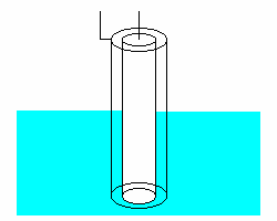 When the fuel level in the tank changes, the relative dielectric constant of the space between the capacitor plates changes, since the dielectric constant of the fuel and air is generally different. And since the capacitance is directly proportional to the dielectric constant of the insulator, the capacitance of the sensor changes as a result. The sensors are mostly made of aluminum or copper, because they are least affected by aggressive media. Of the many ways of measuring the capacitance capacitance value and the subsequent conversion of its capacitance into a proportional change in the DC voltage at the output, the pulse-width method was chosen as fairly simple and reliable, but providing the necessary level of measurement accuracy. Immediately a reservation is required, it is the easiest in terms of finance and fairly simple in terms of building a FLS method for determining the level of diesel fuel.
')
2. Description of the electrical circuit of the fuel level sensor
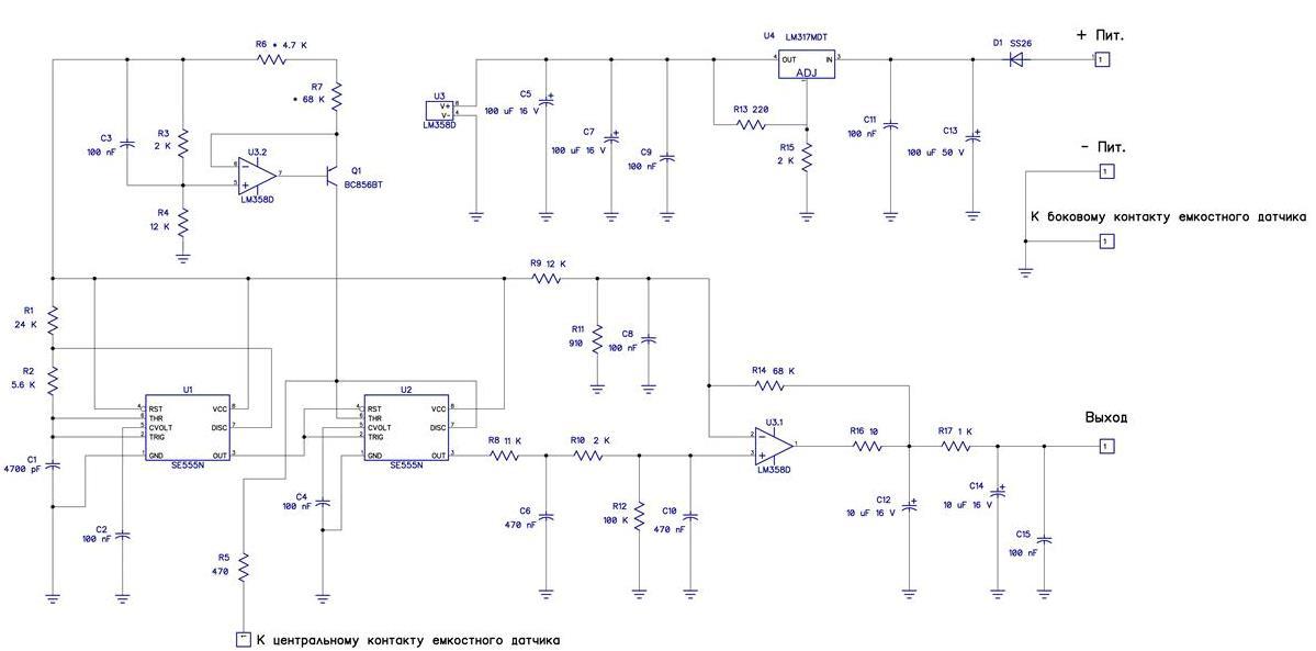
Fig 2. Schematic diagram of the fuel level sensor (FLS) (a large diagram here )
To increase the stability and accuracy of the readings, all elements of the circuit are used with a minimum temperature coefficient. Resistors are used with 1% tolerance, chips are selected with improved parameters, unlike household analogs, for example: SE555N instead of NE555N, and LM358D instead of LM258D.
On the chip U1 SE555N and the elements R1, R2 and C1 assembled master oscillator. Since the stability of the readings strongly depends on it, the K71-7 precision polystyrene capacitor 1% is used as the capacitor C1, they were usually installed on Soviet color television sets in the horizontal scan generators. You can replace it with something modern, but the availability and price of these capacitors makes them very attractive, and they were born back in the distant year, when the USSR was very good at monitoring the quality of the elements produced.
From the output of the 3rd U1 chip, rectangular pulses trigger a one-shot collected on the U2 SE555N chip. As a one-shot capacitor, a sensor placed in the fuel is used, so its capacity will depend on the fuel level, and therefore, the width of the pulse at output 3 of the U2 chip will also change from the fuel level.
To ensure the linear dependence of the pulse width on the fuel level of the sensor, the fuel sensor receives charging current from the current stabilizer made on the U3.2 chip and the Q1 BC856BT transistor. Also, by changing the charging current, the circuit is tuned to different sensor sizes. Setting up the circuit is carried out by selecting resistors R6 and R7, to obtain 1.8-1.9 volts at the output of the circuit, with a "dry" sensor.
From output 3 of the U2 chip, the pulses go to the integrator assembled on the R8 and C6 elements.
Next, the integrated voltage formed on the capacitor C6 is fed to a low-pass filter, made on R10 and C10.
Then the constant voltage goes to the DC amplifier, made on the chip U3.1.
From the output of the 1st chip U3.2, the signal, through a filter made on the elements R17, C12, C14 and C15, goes to the output.
Resistor R16 is used to prevent self-excitation of the amplifier when operating on a capacitive load.
The divider is made on resistors R9 and R11 provides the necessary constant bias for the operation of the DC amplifier in a linear mode.
Voltage stabilizer for the power supply of the electronic circuit is placed according to the classical circuit on the U4 LM317MDT chip.
As a result, at the output, we get an analog signal empty tank 1.8V full 6.0V (there is a dependence on the height of the FLS), which is linear and directly proportional to the level of fuel in the tank \ tank \ storage. Then, using the Kalman filter, you can remove the fuel jumps, display the calculation of the average consumption, etc.
In reality, it will look something like this:
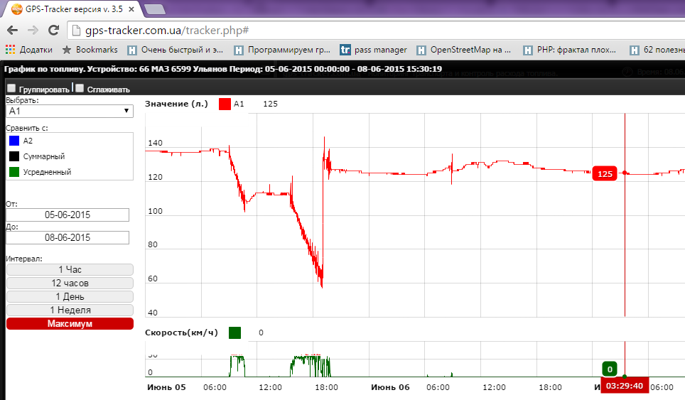
Fuel level chart + speed.
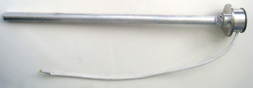
3. Drawing of the fuel level sensor materials
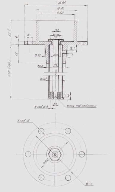
FIGURE 3. Fuel level sensor drawing ( link to large drawing )
It has already been mentioned that aluminum is mainly used, as can be seen from the drawing, the outer tube is soldered in any convenient way to the “head” of the FLS. In the production of our sensors, we use welding, because we have access to it, albeit not the most aesthetically beautiful option, but reliable and time-tested. Inside, an aluminum rod is used, for fixing which a thread is cut in the upper part. Sleeves are used from a special fluoroplastic that is most tolerant of diesel fuel.
4. Summary
On this decision, the vast majority of fuel level sensors on the GPS market of the CIS and the world are built. Each manufacturer makes its own changes to increase the accuracy of fuel level measurements, such as an accelerometer, temperature sensors, digital signal processing, and so on. The scheme I presented is the simplest, ready to work, as they say, in the fields without any difficulties. Dear reader with direct hands, it can easily make any improvements that can be used both for their own purposes and for commercial needs.
Ps. A little eroticism about how such a good is installed on the technique can be found here .
Source: https://habr.com/ru/post/259897/
All Articles