Model rover MSL Curiosity
On the habre many times there were various kitchen bots and I, as an engineer, also always wanted to make my own. Moreover, I saw him necessarily with a controlled camera and a manipulator. The decision to build not just a hand on wheels, but a model of a Martian scientific laboratory, was taken for granted. What could be better than making a model of a real rover with the same functionality that I needed?
In the end, after three years of very slow work, heaps of rework and rakes, I got this:
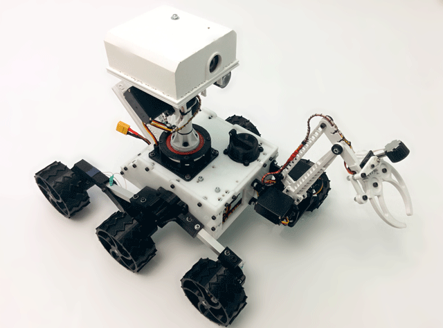
When building a model, I did not aim to make an exact copy of the real rover. I drew it on the basis of what element base was available to me and was content with a distant resemblance to the original. The main motive for me was self-study. Unexpected, side and very pleasant for me, was the effect of popularizing the mission of Curiosity and 3D printing. To my surprise, I found that many people around me had never heard anything about the rover, or that 3D printing was already a fairly affordable technology.
')
To begin with, what was most interesting for me was electronics. One could say that it is made on the Arduino, but I disagree with that. A little later, I will explain why I think so.
To build the model, I used the following ready parts:
If it is so rough to count, then a little more than $ 300 comes out. But we must understand that this amount does not take into account a bunch of small things, samples, errors, etc.
Below I have drawn a conditional block diagram of the electronics of the entire system. I marked the power lines in red and the data lines in blue.
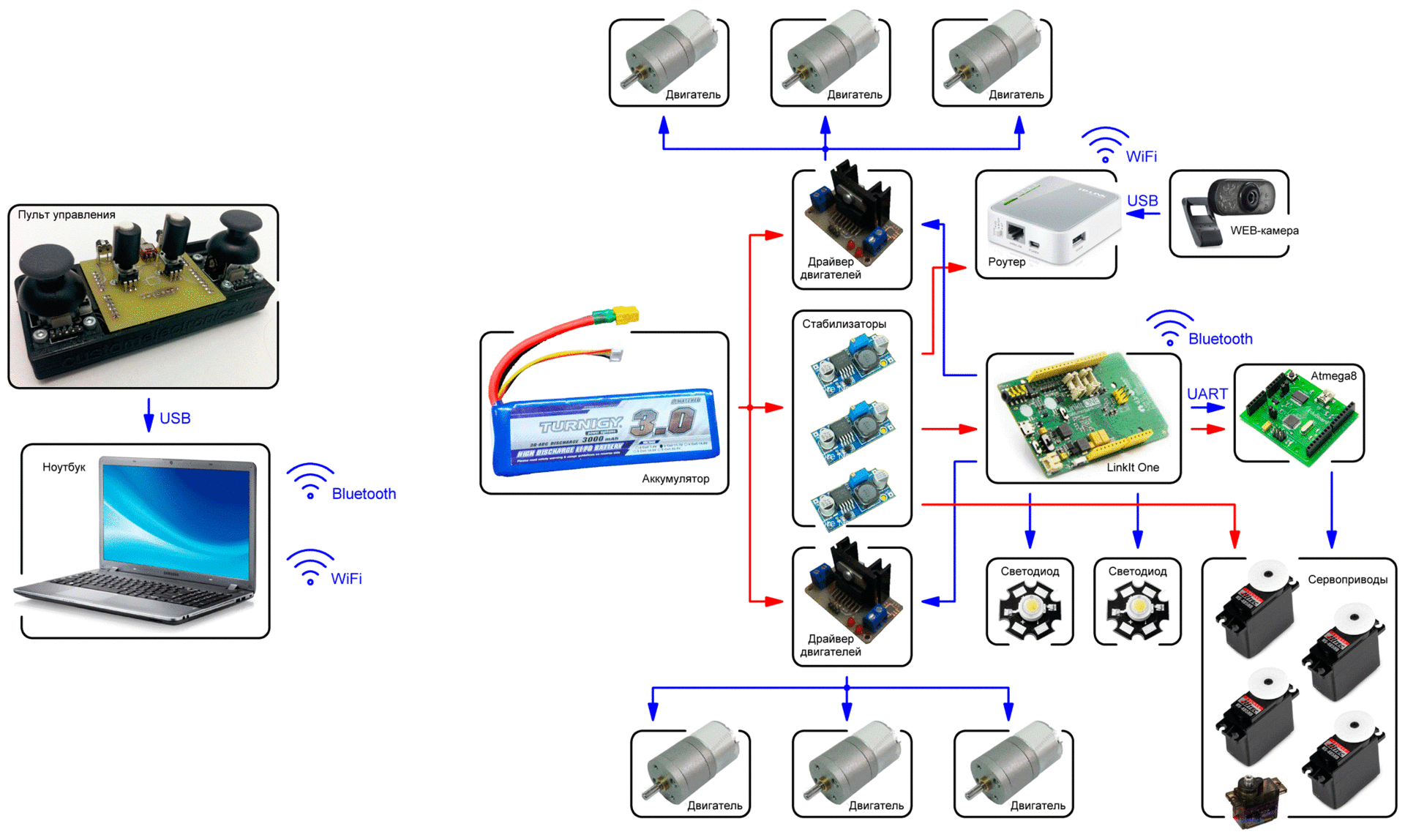
The control panel is connected to the PC via USB. The computer, in turn, is connected to LinkIt One via Bluetooth and transmits operator commands. LinkIt One translates these commands into motor and LED control signals, which it controls itself through drivers and transistors.
Unfortunately, LinkIt One alone can control only two servos. Therefore, a link on the Atmega8 microcontroller is connected to LinkIt One via UART. It accepts the required angles and generates accurate signals to control five servo drives.
The router in this scheme costs practically separately. It is supplied only with power and it begins to transmit a picture from the camera.
Powered by the battery rover. Direct battery voltage is supplied only to the drivers of the motors. For the remaining modules of the scheme, three five-volt converters are used, namely for the router, logic and servo drives.
All electronics, except for the router with the camera, are hidden inside the “body” of the rover model. It may seem that there is a small mess, but in fact, if you collect all the wires in harnesses (and this is all ready), it will be much neater. Just while I'm not in a hurry to fully complete work on the model.
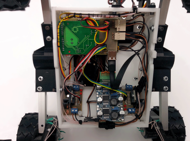
By the way, I made a small circuit board through which LinkIt One connects to EduBoard. It also has power, signal connectors and keys for controlling the backlight.
I do not plan to lay out the sources. It is unlikely that someone will want to repeat all this one to one. If there are questions, I will gladly tell you more or send the materials of interest.
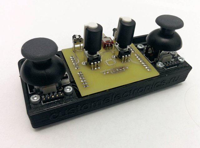
The console is assembled on the basis of the same EduBoard , shield to it and two joysticks.
The shield contains all the controls, namely two variable resistors, two buttons and two toggle switches. Both joysticks are connected to it. Signals from all these devices are processed by six channels of the microcontroller's ADC, two digital inputs and two external interrupt inputs. The received data is normalized, wrapped around a protocol and, via FT232RL, sent to a computer at a frequency of 10 Hz.
The body of the console is printed on a 3D printer:
During these three years, I managed to remake it twice. It was originally made of fiberglass, but the mechanics in it were thought out very badly. Then I made it from plexiglass. He even worked, but I didn’t show him to anyone, because he looked just awful.
The turning point in the work on the project was the acquisition by the radio engineering college , in which I teach a little, the PrintBox One 3D printer. As a result, most of the details for it are printed on a 3D printer. The body is made of plexiglass, and the cover of the "head" of fiberglass.

I most often draw in sketchup. Only wheel drawings, which are a bit more complicated, were prepared in SolidWorks by my friend, a professional designer. Files for cutting plexiglass made in NanoCad. Before I started making the rover, I made it a virtual model. All project files for 3D printing and cutting plexiglass are posted on thingiverse.com . There are quite a few useful pieces that can be applied in other projects.
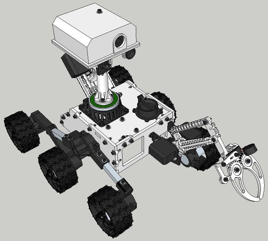
It turned out, in my opinion quite well. He is highly disproportionate, but it even adds some charm to him. The wife generally says that he looks like Valli.
All mechanical assemblies work through the bearings, so the servos do not even strain to keep the parts of the head and the manipulator. The suspension does not even remotely repeat the functions of the original, but it works and allows the rover to overcome small obstacles. Plastic wheels are not very effective on laminate, but, I think, on the ground or sand would be generally excellent. As soon as I print a spare batch of wheels, I'll try.
This is where I’ll talk about why I don’t think this is an Arduino. In total, four programs are used for the rover model.
The first, written in C, is performed on the remote. I already wrote about its functions above.
The second program for the PC. It is written in Python. It was originally planned that the computer will receive commands, recalculate them and send to the rover in processed form. As a result, LinkIt One is involved in all calculations, and the Python script only redirects bytes received from the console to a Bluetooth device.
LinkIt One is programmed in C ++. It accepts packets from a PC (which reach exactly the same form that the console forms them), controls the motors and the light itself, and also recalculates the angles of the servos and sends them to the servo controller. Commands for engines are driven through a proportional controller to ensure smooth control and eliminate the possibility of abrupt changes in the direction of rotation of the engines.
The fourth program, written in C, controls the servos. It accepts commands from the UART and, according to the algorithm that I have already described , generates control pulses for servos.
All this software allows you to manage it smoothly without jerking. After a little training, I confidently collect items from the floor. It is specially made a bit "inhibited" and inertial. If the servos were twitching with maximum speed, it would look much worse.
As you can see, I use hardware compatibility with Arduino and their bootloaders, but the code for the project is not written in Processing / Wiring. Therefore, I do not think that it is an arduino hack.
Source can also share on request. Only there it is necessary to clean a lot of harkod and I plan to refine the manipulator's math.
OpenWrt firmware is installed on the router. When enabled, the router creates an access point and raises the web server with the page that broadcasts the video.
On my firmware, the most optimal quality is obtained at a frame rate of 5 times per second in QCIF format (176x144). It's pretty small, but enough to drive around the apartment. You can, of course, increase the frequency or resolution, but then begin to skip beaten frames.
Here's what the picture from the head looks like in the original resolution:

That's how my rover model looks and works at the moment:
Slightly earlier video for thingiverse:
One more thing. With broken servos, but overcoming obstacles:
Of course, first of all I did all this to familiarize myself with many technologies that I did not use for work. It is especially pleasant that the model turned out to be interesting also for those who love space and 3D printing.
During the work on the project a lot of scattered information has accumulated and I can and want to share some of my research in Habré. Take this opportunity to ask a couple of questions about how interesting this can be.
In the end, after three years of very slow work, heaps of rework and rakes, I got this:

When building a model, I did not aim to make an exact copy of the real rover. I drew it on the basis of what element base was available to me and was content with a distant resemblance to the original. The main motive for me was self-study. Unexpected, side and very pleasant for me, was the effect of popularizing the mission of Curiosity and 3D printing. To my surprise, I found that many people around me had never heard anything about the rover, or that 3D printing was already a fairly affordable technology.
')
Hardware
To begin with, what was most interesting for me was electronics. One could say that it is made on the Arduino, but I disagree with that. A little later, I will explain why I think so.
To build the model, I used the following ready parts:
- Fee LinkIt One , as the main brain of the rover ($ 79)
- Two boards on the Atmega8 EduBoard microcontroller, which I use to teach microcontroller programming. In the model, one of them is used for the remote, and the second is for controlling the servos ($ 21)
- Four servo Hitec HS-485 ($ 58)
- One MG-90S servo with a metal gearbox ($ 4.5)
- Six DC gear motors , 77 rpm ($ 48)
- TP-LINK TL-MR3020 WiFi router ($ 26.7)
- WEB-camera Logitec C210 (no longer produce) (about $ 20)
- Three voltage regulators 5V, 3A ($ 17.2)
- Two Turnigy LiPo-batteries , 3S, 3000mAh ($ 26.4)
- Two self-made engine drivers (about $ 7)
If it is so rough to count, then a little more than $ 300 comes out. But we must understand that this amount does not take into account a bunch of small things, samples, errors, etc.
Below I have drawn a conditional block diagram of the electronics of the entire system. I marked the power lines in red and the data lines in blue.

The control panel is connected to the PC via USB. The computer, in turn, is connected to LinkIt One via Bluetooth and transmits operator commands. LinkIt One translates these commands into motor and LED control signals, which it controls itself through drivers and transistors.
Unfortunately, LinkIt One alone can control only two servos. Therefore, a link on the Atmega8 microcontroller is connected to LinkIt One via UART. It accepts the required angles and generates accurate signals to control five servo drives.
The router in this scheme costs practically separately. It is supplied only with power and it begins to transmit a picture from the camera.
Powered by the battery rover. Direct battery voltage is supplied only to the drivers of the motors. For the remaining modules of the scheme, three five-volt converters are used, namely for the router, logic and servo drives.
All electronics, except for the router with the camera, are hidden inside the “body” of the rover model. It may seem that there is a small mess, but in fact, if you collect all the wires in harnesses (and this is all ready), it will be much neater. Just while I'm not in a hurry to fully complete work on the model.

By the way, I made a small circuit board through which LinkIt One connects to EduBoard. It also has power, signal connectors and keys for controlling the backlight.
I do not plan to lay out the sources. It is unlikely that someone will want to repeat all this one to one. If there are questions, I will gladly tell you more or send the materials of interest.
Remote Control
The console is assembled on the basis of the same EduBoard , shield to it and two joysticks.
The shield contains all the controls, namely two variable resistors, two buttons and two toggle switches. Both joysticks are connected to it. Signals from all these devices are processed by six channels of the microcontroller's ADC, two digital inputs and two external interrupt inputs. The received data is normalized, wrapped around a protocol and, via FT232RL, sent to a computer at a frequency of 10 Hz.
The body of the console is printed on a 3D printer:

Rover body
During these three years, I managed to remake it twice. It was originally made of fiberglass, but the mechanics in it were thought out very badly. Then I made it from plexiglass. He even worked, but I didn’t show him to anyone, because he looked just awful.
The turning point in the work on the project was the acquisition by the radio engineering college , in which I teach a little, the PrintBox One 3D printer. As a result, most of the details for it are printed on a 3D printer. The body is made of plexiglass, and the cover of the "head" of fiberglass.

A couple more photos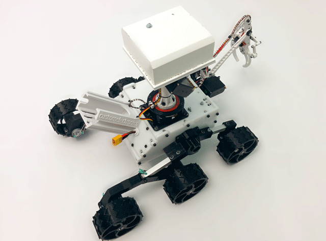


I most often draw in sketchup. Only wheel drawings, which are a bit more complicated, were prepared in SolidWorks by my friend, a professional designer. Files for cutting plexiglass made in NanoCad. Before I started making the rover, I made it a virtual model. All project files for 3D printing and cutting plexiglass are posted on thingiverse.com . There are quite a few useful pieces that can be applied in other projects.

It turned out, in my opinion quite well. He is highly disproportionate, but it even adds some charm to him. The wife generally says that he looks like Valli.
All mechanical assemblies work through the bearings, so the servos do not even strain to keep the parts of the head and the manipulator. The suspension does not even remotely repeat the functions of the original, but it works and allows the rover to overcome small obstacles. Plastic wheels are not very effective on laminate, but, I think, on the ground or sand would be generally excellent. As soon as I print a spare batch of wheels, I'll try.
Software
This is where I’ll talk about why I don’t think this is an Arduino. In total, four programs are used for the rover model.
The first, written in C, is performed on the remote. I already wrote about its functions above.
The second program for the PC. It is written in Python. It was originally planned that the computer will receive commands, recalculate them and send to the rover in processed form. As a result, LinkIt One is involved in all calculations, and the Python script only redirects bytes received from the console to a Bluetooth device.
LinkIt One is programmed in C ++. It accepts packets from a PC (which reach exactly the same form that the console forms them), controls the motors and the light itself, and also recalculates the angles of the servos and sends them to the servo controller. Commands for engines are driven through a proportional controller to ensure smooth control and eliminate the possibility of abrupt changes in the direction of rotation of the engines.
The fourth program, written in C, controls the servos. It accepts commands from the UART and, according to the algorithm that I have already described , generates control pulses for servos.
All this software allows you to manage it smoothly without jerking. After a little training, I confidently collect items from the floor. It is specially made a bit "inhibited" and inertial. If the servos were twitching with maximum speed, it would look much worse.
As you can see, I use hardware compatibility with Arduino and their bootloaders, but the code for the project is not written in Processing / Wiring. Therefore, I do not think that it is an arduino hack.
Source can also share on request. Only there it is necessary to clean a lot of harkod and I plan to refine the manipulator's math.
Video transfer
OpenWrt firmware is installed on the router. When enabled, the router creates an access point and raises the web server with the page that broadcasts the video.
On my firmware, the most optimal quality is obtained at a frame rate of 5 times per second in QCIF format (176x144). It's pretty small, but enough to drive around the apartment. You can, of course, increase the frequency or resolution, but then begin to skip beaten frames.
Here's what the picture from the head looks like in the original resolution:

Video work
That's how my rover model looks and works at the moment:
Slightly earlier video for thingiverse:
One more thing. With broken servos, but overcoming obstacles:
Instead of conclusion
Of course, first of all I did all this to familiarize myself with many technologies that I did not use for work. It is especially pleasant that the model turned out to be interesting also for those who love space and 3D printing.
During the work on the project a lot of scattered information has accumulated and I can and want to share some of my research in Habré. Take this opportunity to ask a couple of questions about how interesting this can be.
Source: https://habr.com/ru/post/259847/
All Articles