Oberon system implemented on an affordable FPGA board
by Niklaus Wirth
Professor (retired)
Swiss Federal Institute of Technology (ETH)
Zurich, Switzerland
In 1988, Jürg Gutknecht and I completed and published the Oberon programming language [1, 2], which was the successor to the two other languages, Pascal and Modula-2, which I developed earlier. Oberon language was designed by us initially as more rational and efficient than Modula-2, which made it easier for students of the academic education system to master computer science. Not stopping there, in 1990 we built an Oberon for workstations using windows and text processing capabilities. Then we published a book revealing the details of both the Oberon compiler and the OS of the same name. The book, entitled "Project Oberon", included the source code of the system.
A few years later, my friend Paul Reed suggested that I publish a reprint of the book, because of its importance for the study of system architecture and giving a good starting point for those who want to build reliable systems from scratch.
However, there was a serious obstacle. The original compiler was created for a processor that has already disappeared from the market. So I decided to rewrite the compiler for a modern processor. But in the course of a small study, I could not find a processor that fully meets my criteria for clarity, regularity and simplicity. So I had to design my own processor. This idea was realized thanks to a modern PPVM chip (user-programmable gate array, FPGA), which allowed me to create hardware in the same way as a software system is created. Moreover, the choice of Xilinx® FPGA gave me the opportunity to remake the system without deviating much from the original project of 1990.
')
The new RISC processor is implemented on an inexpensive Digilent Spartan®-3 card with a single megabyte static memory module (SRAM). All my hardware improvements related to the mouse interface and the SD card, replacing the hard drive in the old system.
The book and the source code of the entire system are available at projectoberon.com [3,4,5]. A separate S3RISCinstall.zip file is also available there . It contains instructions, a file system image for the SD card and bit configuration files for the FPGA (in the form of PROM files for the Spartan-3 flash memory), structural parts for the hardware interface of the SD card and the mouse.
RISC processor
The processor is represented by a RISC5 Verilog module and consists of an arithmetic logic unit (ALU), an array of sixteen 32-bit registers and a control module with an IR instruction register and a PC software counter (for more details see approx. Transl.).
The processor processes 20 instructions: four for moving, shifting, and rotating; four for logical operations; four for integer arithmetic; four for floating point calculations; two for memory access and two for branching.
RISC5 is imported from the RISC5Top context (environment) containing interfaces for various devices mapped to memory and SRAM (256 MB x 32 bits). The whole system (Fig. 1) Fig. 1. System diagram with Verilog modules.
contains the following Verilog modules (the number of lines of each module is shown):
I mapped a black and white VGA display into memory so that it occupies 1024 x 768 x 1 bit per pixel = 98,304 bytes, essentially 10 percent of the total available memory of 1 megabyte. The SD card, which replaced 80 megabytes from the original system, is accessed via a standard SPI interface that accepts and serializes bytes or 32-bit words. The keyboard and mouse are connected via a standard PS-2 serial interface. In addition, there are cables for serial asynchronous RS-232 and a multipurpose 8-bit parallel I / O interface. Also, the RISC5Top module contains a millisecond counter.
Operating system Oberon
The OS software includes a kernel that includes a memory allocator with the garbage collector, a file system along with the loader, a text system, a viewer system, and a text editor.
The module called “Oberon” is the central task manager, and “System” is the basic command module. The action (action) is invoked by clicking the middle mouse button on the text of the form “MP” in any display on the display, where P is the name of the procedure declared in module M. If M is not available, it is automatically loaded.
Most text editing commands are triggered by normal mouse clicks, in which the left button serves the carriage marking the current position in the text, and the right button is responsible for selecting the text.
The Kernel module includes disk storage (disk-store management) and a garbage collector.
Viewers are tiled and do not overlap each other. Standard markup displays two vertical tracks with an unlimited number of browsers. You can increase or decrease them, as well as drag them for the title strip. In fig. Figure 2 shows the user interface on a monitor connected to a Spartan-3 board with a keyboard and mouse.
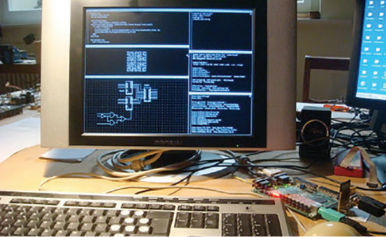
Fig. 2. The user interface on the monitor and the Spartan-3 at the bottom right.
The loaded system is 112.640 bytes in the modular space (21 percent) and 16,128 bytes on the heap (3 percent). It consists of the following modules (with the number of lines each), shown in Fig. 3:
 It is worth noting that loading the system when it is turned on or restarted takes only 2 seconds, including scanning the file directory for garbage collection.
Oberon Compiler
The compiler is built into the system and uses a simple method of recursive downward parsing. Compiler activation is done using the ORP.Compile @ command. The parser receives characters from a scanner that handles identifiers, numbers, and special characters (such as BEGIN, END, +, and others). This scheme has proven its suitability and elegance in many applications and is described in my book Compiler Construction [6,7].
The parser calls the procedures from the code-generation module, which directly add instructions to the code array. Branch instructions are formed by jump addresses at the very end of the compilation, when all transition points are already known.
All variable addresses are calculated relative to the base register. This is R14 (stack pointer) for local variables (specified when entering the procedure in runtime), or R13 for global and imported variables. Base addresses are loaded on request from the global module table, whose address is stored in register R12. Register R15 is used for return addresses according to the RISC architecture. The remaining registers, R0 - R11, are available for evaluating expressions and passing procedural parameters.
The entire compiler consists of four relatively small and efficient modules (the number of lines of each is indicated):
The compiler occupies 115.912 bytes (22 percent) of the modular space and 17.508 bytes (4 percent) of the heap (before compilation). Its source code is about 65 kilobytes. Compiling the compiler itself takes only a few seconds on a 25-MHz RISC processor [8].
The compiler always generates checks for array indices and pointers to NIL. This creates traps (trap, trap - approx. Transl.) In case of violation. This technique guarantees a high level of protection against errors and damage. In fact, the integrity of the system can be broken only by using such SYSTEM pseudo-module operations, such as PUT and COPY. These operations should be used in a limited way, only in device driver modules and easy to find by the name SYSTEM in the import list. The whole system is programmed on Oberon itself, without using assembly codes.
I chose the Digilent Spartan-3 board because of its affordability and simplicity, which makes it suitable for educational institutions purchasing entire sets for classes. The big benefit is also in the presence of static RAM on the board, which allows you to connect (interfacing) directly (and even read bytes). Unfortunately, newer boards use dynamic RAM, which, although more capacious, is more difficult to connect, requires additional circuits for updating and initialization (calibration). Such circuitry may be no less complex than the entire processor with static RAM. Even if the controller is supplied on a chip, it violates our principle that everything should be available for control.
Last thoughts
More than 40 years ago, C. Hoar noted that in all branches of science and technology, students are influenced by a large number of examples of serious constructions before gaining their own experimental experience. Programming and program design emphasize this paradigm. Students have to write programs from the very beginning, instead of studying various samples.
The reason for such a terrible situation was that there was almost no literature with qualified examples. Therefore, I decided to rectify the situation and wrote the book Algorithms and Data Structures in 1975. Later (together with J. Gutknecht), in the framework of teaching the course of operating systems, I designed the Oberon system (1986–88).
After a while, the teaching of programming did not receive a noticeable improvement due to the fact that the systems dramatically complicated and increased in size. Although the open course was recognized, it could not change the situation, since most of the programs are created just to start them as soon as possible, and not for a better understanding of them by man.
I continue to make bold assumptions that all programs should be created not only for the computer, but also for human understanding. They should be available. This task is much more difficult than creating executable programs, even if they are correct and effective. This implies that there should be no assembler inserts.
The result of ignoring the human factor leads to the fact that everywhere there are not very carefully designed applications, brought to the working state by debugging, sometimes with grim consequences. To achieve comprehensibility, it is worth adhering to simplicity and order, refusing unnecessary decorations and, avoiding hand bells with whistles, distinguish between conventional and suitable (conventional and convenient).
The small size of such systems shows how small things can be achieved. OS Oberon is ridiculously small in comparison with modern operating systems, although it includes a file system, a text editor and a window system. A side effect is that a few simple rules are very easy to learn for future reference.
Finally, the advantage of brevity is that it is safe to build on such a system without fear of unknown possibilities, such as back doors. This is an essential feature that is very important for systems that are critical to security issues, given the increasing danger of attacks on the integrity of systems. It is equally important that the hardware of our system does not contain any hidden parts. No one can give guarantees for systems built on a foundation that is inaccessible for understanding in its entirety.
Thanks
I am very grateful to Paul Reed for his invaluable contribution. He suggested that I edit the book “Project Oberon” and also offered to re-implement the entire system on FPGA. Paul was an inexhaustible source of encouragement. Replacing the disk with an SD card was his idea and he also provided SPI, PS-2 and VID Verilog interfaces.
Links
1. www.inf.ethz.ch/personal/wirth/Oberon/Oberon07.Report.pdf
2. www.inf.ethz.ch/personal/wirth/Oberon/PIO.pdf
3. www.inf.ethz.ch/personal/wirth/ProjectOberon/index.html
4. www.inf.ethz.ch/personal/wirth/Oberon/PIO.pdf
5. www.inf.ethz.ch/personal/wirth/Oberon/Oberon07.Report.pdf
6. www.inf.ethz.ch/personal/wirth/CompilerConstruction/CompilerConstruction1.pdf
7. www.inf.ethz.ch/personal/wirth/CompilerConstruction/CompilerConstruction2.pdf
8. www.inf.ethz.ch/personal/wirth/ProjectOberon/PO.Applications.pdf (Ch. 12)
application
A hardware description language (HDL), called Lola, was defined in 1990 to teach the fundamentals of hardware design. It was a time when textual definitions began to replace circuit diagrams and at the same time the first FPGAs became available, although they had not yet reached the industrial level. For Lola, a compiler was generated that generates bit files suitable for loading into FPGA. Bit file formats are disclosed by Algotronix, Inc. and Concurrent Logic Inc. Both formats made it possible to work with cells of fairly simple structures that are optimal for automatic wiring.
As a result of my project to rework Oberon for the FPGA, the idea arose of reviving Lola as well. Since Xilinx FPGA cells are more complex, we didn’t risk making efforts to implement placement and layout, regardless of the fact that Xilinx refused to open its patented bit-file format.
The obvious solution was to build a Lola compiler that would not generate proprietary bit files, but would allow it to be translated into a language for which Xilinx provides a special tool. We chose Verilog. This solution implied a somewhat extravagant workaround: first, the Lola module must be parsed, then translated, and eventually it will be parsed again. At all these stages, we must ensure that the Lola compiler has proper error control and type checking capabilities.
To push the development of Lola-2, we needed to reformulate all the modules of the RISC5 processor on Lola. What was done.
Lola language
Lola is a small, laconic language in the Oberon style (see www.inf.ethz.ch/personal/wirth/Lola/Lola2.pdf ). For the sake of brevity, we will show here only one example of text on Lola (Fig. 1). The unit of source text is called a module. Its header defines the module name, the names and types of input and output parameters. The header is followed by a section of declarations of local objects, such as variables and registers. Next is the section for determining the values of variables and registers. BYTE defines an array of 8 bits.
Fig. 1. The source text on Lola shows the seconds and milliseconds counter displayed on the board indicators.
Lola compiler
The compiler uses a simple method of recursive downward parsing. It is activated on the selected Lola source code with the LSC.Compile @ command. The parser receives characters from a scanner that handles identifiers, numbers, and special characters (such as BEGIN, END, +, and others). This scheme has proven its suitability and elegance in many applications and is described in the book Compiler Construction (Part 1 and 2).
Instead of generating Verilog texts on the fly, the parser first creates a tree of operators, which is more suitable for further processing. This approach has the advantage that any required output can be easily generated by a suitable translator. One of these is the translator in Verilog. The first LSV.List command is outputfile.v. Another team can translate to VHDL or simply display a tree. The third can generate a netlist for further processing by the razvodchik.
Thus, the entire compiler consists of at least four relatively small and efficient modules:
Transaction instructions from Lola to Verilog can be found here: www.inf.ethz.ch/personal/wirth/Lola/LolaCompiler.pdf .
Differences between software and hardware "programs"
Many efforts have been made in the past to make HDL languages look like “normal” programming languages. In addition, HDL have "twins" among other PL, adapting to their style. For example, Verilog is derived from C, VHDL from Ada, and Lola from Oberon. But we believe that it is important to see the fundamental differences between these two classes, in particular, in the presence of syntactic similarities, or even identities. What are these fundamental differences?
To simplify the explanation, we will limit our analysis to synchronous circuits — that is, those in which all registers are tied to one clock generator. In general, synchronous schemes are a good architectural paradigm, which should be followed, if possible.
Further, it is abundantly clear that all elements of the scheme work simultaneously, literally at the same time. Each variable and each register are determined by one and only one expression (combinational circuit). Multiple assignments are meaningless. We can easily imagine each HDL program to be enclosed in a large infinite loop, since assignments to registers and variables occur every cycle.
The idea of John von Neumann to present a processor architecture based on a sequencer (sequencer) was ingenious. The sequencer contains a register of instructions, according to which certain patterns are selected and the others are ignored in each measure, which leads to skillful reuse of various parts of the ALU. Tacts or steps are consistent in nature, so it is possible to reassign values to variables according to how the program counter relates them to specific places in the program and in the sequence of instructions. The idea of the sequencer made it possible to run huge programs on relatively simple circuits.
So, Lola-2 is the HDL in the style of Yap Oberon. The compiler presented here translates Lola modules into Verilog modules. The advantages of Lola are both in the simple and familiar structure of the language, and in emphasizing the compiler for type checking and advanced error diagnostics. A complete set of modules for the RISC processor, described on Lola: www.inf.ethz.ch/personal/wirth/Lola/index.html
Professor (retired)
Swiss Federal Institute of Technology (ETH)
Zurich, Switzerland
In 1988, Jürg Gutknecht and I completed and published the Oberon programming language [1, 2], which was the successor to the two other languages, Pascal and Modula-2, which I developed earlier. Oberon language was designed by us initially as more rational and efficient than Modula-2, which made it easier for students of the academic education system to master computer science. Not stopping there, in 1990 we built an Oberon for workstations using windows and text processing capabilities. Then we published a book revealing the details of both the Oberon compiler and the OS of the same name. The book, entitled "Project Oberon", included the source code of the system.
A few years later, my friend Paul Reed suggested that I publish a reprint of the book, because of its importance for the study of system architecture and giving a good starting point for those who want to build reliable systems from scratch.
However, there was a serious obstacle. The original compiler was created for a processor that has already disappeared from the market. So I decided to rewrite the compiler for a modern processor. But in the course of a small study, I could not find a processor that fully meets my criteria for clarity, regularity and simplicity. So I had to design my own processor. This idea was realized thanks to a modern PPVM chip (user-programmable gate array, FPGA), which allowed me to create hardware in the same way as a software system is created. Moreover, the choice of Xilinx® FPGA gave me the opportunity to remake the system without deviating much from the original project of 1990.
')
The new RISC processor is implemented on an inexpensive Digilent Spartan®-3 card with a single megabyte static memory module (SRAM). All my hardware improvements related to the mouse interface and the SD card, replacing the hard drive in the old system.
The book and the source code of the entire system are available at projectoberon.com [3,4,5]. A separate S3RISCinstall.zip file is also available there . It contains instructions, a file system image for the SD card and bit configuration files for the FPGA (in the form of PROM files for the Spartan-3 flash memory), structural parts for the hardware interface of the SD card and the mouse.
RISC processor
The processor is represented by a RISC5 Verilog module and consists of an arithmetic logic unit (ALU), an array of sixteen 32-bit registers and a control module with an IR instruction register and a PC software counter (for more details see approx. Transl.).
The processor processes 20 instructions: four for moving, shifting, and rotating; four for logical operations; four for integer arithmetic; four for floating point calculations; two for memory access and two for branching.
RISC5 is imported from the RISC5Top context (environment) containing interfaces for various devices mapped to memory and SRAM (256 MB x 32 bits). The whole system (Fig. 1)
contains the following Verilog modules (the number of lines of each module is shown):
| RISC5Top | environment | 194 |
| RISC5 | processor | 201 |
| Multiplier | integer arithmetic | 47 |
| Divider | 24 | |
| FPAdder | floating-point arithmetic | 98 |
| FPMultiplier | 33 | |
| FPDivider | 35 | |
| SPI | SD card and transmitter / receiver | 25 |
| Vid | 1024 x 768 video controller | 73 |
| PS2 | keyboard | 25 |
| Mouse | mouse | 95 |
| RS232T | RS232 transmitter | 23 |
| RS232R | RS232 receiver | 25 |
I mapped a black and white VGA display into memory so that it occupies 1024 x 768 x 1 bit per pixel = 98,304 bytes, essentially 10 percent of the total available memory of 1 megabyte. The SD card, which replaced 80 megabytes from the original system, is accessed via a standard SPI interface that accepts and serializes bytes or 32-bit words. The keyboard and mouse are connected via a standard PS-2 serial interface. In addition, there are cables for serial asynchronous RS-232 and a multipurpose 8-bit parallel I / O interface. Also, the RISC5Top module contains a millisecond counter.
Operating system Oberon
The OS software includes a kernel that includes a memory allocator with the garbage collector, a file system along with the loader, a text system, a viewer system, and a text editor.
The module called “Oberon” is the central task manager, and “System” is the basic command module. The action (action) is invoked by clicking the middle mouse button on the text of the form “MP” in any display on the display, where P is the name of the procedure declared in module M. If M is not available, it is automatically loaded.
Most text editing commands are triggered by normal mouse clicks, in which the left button serves the carriage marking the current position in the text, and the right button is responsible for selecting the text.
The Kernel module includes disk storage (disk-store management) and a garbage collector.
Viewers are tiled and do not overlap each other. Standard markup displays two vertical tracks with an unlimited number of browsers. You can increase or decrease them, as well as drag them for the title strip. In fig. Figure 2 shows the user interface on a monitor connected to a Spartan-3 board with a keyboard and mouse.
Fig. 2. The user interface on the monitor and the Spartan-3 at the bottom right.
The loaded system is 112.640 bytes in the modular space (21 percent) and 16,128 bytes on the heap (3 percent). It consists of the following modules (with the number of lines each), shown in Fig. 3:
| Kernel | 271 (inner core) |
| Filedir | 352 |
| Files | 505 |
| Modules (loader) | 226 |
| Viewers | 216 (outer core) |
| Texts | 532 |
| Oberon | 411 |
| Menuviewers | 208 |
| Textframes | 874 |
| System | 420 |
| Edit | 233 |
It is worth noting that loading the system when it is turned on or restarted takes only 2 seconds, including scanning the file directory for garbage collection.Oberon Compiler
The compiler is built into the system and uses a simple method of recursive downward parsing. Compiler activation is done using the ORP.Compile @ command. The parser receives characters from a scanner that handles identifiers, numbers, and special characters (such as BEGIN, END, +, and others). This scheme has proven its suitability and elegance in many applications and is described in my book Compiler Construction [6,7].
The parser calls the procedures from the code-generation module, which directly add instructions to the code array. Branch instructions are formed by jump addresses at the very end of the compilation, when all transition points are already known.
All variable addresses are calculated relative to the base register. This is R14 (stack pointer) for local variables (specified when entering the procedure in runtime), or R13 for global and imported variables. Base addresses are loaded on request from the global module table, whose address is stored in register R12. Register R15 is used for return addresses according to the RISC architecture. The remaining registers, R0 - R11, are available for evaluating expressions and passing procedural parameters.
The entire compiler consists of four relatively small and efficient modules (the number of lines of each is indicated):
| ORP | parser | 968 |
| ORG | code generator | 1120 |
| ORB | base def | 435 |
| ORS | scanner | 311 |
The compiler occupies 115.912 bytes (22 percent) of the modular space and 17.508 bytes (4 percent) of the heap (before compilation). Its source code is about 65 kilobytes. Compiling the compiler itself takes only a few seconds on a 25-MHz RISC processor [8].
The compiler always generates checks for array indices and pointers to NIL. This creates traps (trap, trap - approx. Transl.) In case of violation. This technique guarantees a high level of protection against errors and damage. In fact, the integrity of the system can be broken only by using such SYSTEM pseudo-module operations, such as PUT and COPY. These operations should be used in a limited way, only in device driver modules and easy to find by the name SYSTEM in the import list. The whole system is programmed on Oberon itself, without using assembly codes.
I chose the Digilent Spartan-3 board because of its affordability and simplicity, which makes it suitable for educational institutions purchasing entire sets for classes. The big benefit is also in the presence of static RAM on the board, which allows you to connect (interfacing) directly (and even read bytes). Unfortunately, newer boards use dynamic RAM, which, although more capacious, is more difficult to connect, requires additional circuits for updating and initialization (calibration). Such circuitry may be no less complex than the entire processor with static RAM. Even if the controller is supplied on a chip, it violates our principle that everything should be available for control.
Last thoughts
More than 40 years ago, C. Hoar noted that in all branches of science and technology, students are influenced by a large number of examples of serious constructions before gaining their own experimental experience. Programming and program design emphasize this paradigm. Students have to write programs from the very beginning, instead of studying various samples.
The reason for such a terrible situation was that there was almost no literature with qualified examples. Therefore, I decided to rectify the situation and wrote the book Algorithms and Data Structures in 1975. Later (together with J. Gutknecht), in the framework of teaching the course of operating systems, I designed the Oberon system (1986–88).
After a while, the teaching of programming did not receive a noticeable improvement due to the fact that the systems dramatically complicated and increased in size. Although the open course was recognized, it could not change the situation, since most of the programs are created just to start them as soon as possible, and not for a better understanding of them by man.
I continue to make bold assumptions that all programs should be created not only for the computer, but also for human understanding. They should be available. This task is much more difficult than creating executable programs, even if they are correct and effective. This implies that there should be no assembler inserts.
The result of ignoring the human factor leads to the fact that everywhere there are not very carefully designed applications, brought to the working state by debugging, sometimes with grim consequences. To achieve comprehensibility, it is worth adhering to simplicity and order, refusing unnecessary decorations and, avoiding hand bells with whistles, distinguish between conventional and suitable (conventional and convenient).
The small size of such systems shows how small things can be achieved. OS Oberon is ridiculously small in comparison with modern operating systems, although it includes a file system, a text editor and a window system. A side effect is that a few simple rules are very easy to learn for future reference.
Finally, the advantage of brevity is that it is safe to build on such a system without fear of unknown possibilities, such as back doors. This is an essential feature that is very important for systems that are critical to security issues, given the increasing danger of attacks on the integrity of systems. It is equally important that the hardware of our system does not contain any hidden parts. No one can give guarantees for systems built on a foundation that is inaccessible for understanding in its entirety.
Thanks
I am very grateful to Paul Reed for his invaluable contribution. He suggested that I edit the book “Project Oberon” and also offered to re-implement the entire system on FPGA. Paul was an inexhaustible source of encouragement. Replacing the disk with an SD card was his idea and he also provided SPI, PS-2 and VID Verilog interfaces.
Links
1. www.inf.ethz.ch/personal/wirth/Oberon/Oberon07.Report.pdf
2. www.inf.ethz.ch/personal/wirth/Oberon/PIO.pdf
3. www.inf.ethz.ch/personal/wirth/ProjectOberon/index.html
4. www.inf.ethz.ch/personal/wirth/Oberon/PIO.pdf
5. www.inf.ethz.ch/personal/wirth/Oberon/Oberon07.Report.pdf
6. www.inf.ethz.ch/personal/wirth/CompilerConstruction/CompilerConstruction1.pdf
7. www.inf.ethz.ch/personal/wirth/CompilerConstruction/CompilerConstruction2.pdf
8. www.inf.ethz.ch/personal/wirth/ProjectOberon/PO.Applications.pdf (Ch. 12)
application
Lola language and its translation in Verilog
A hardware description language (HDL), called Lola, was defined in 1990 to teach the fundamentals of hardware design. It was a time when textual definitions began to replace circuit diagrams and at the same time the first FPGAs became available, although they had not yet reached the industrial level. For Lola, a compiler was generated that generates bit files suitable for loading into FPGA. Bit file formats are disclosed by Algotronix, Inc. and Concurrent Logic Inc. Both formats made it possible to work with cells of fairly simple structures that are optimal for automatic wiring.
As a result of my project to rework Oberon for the FPGA, the idea arose of reviving Lola as well. Since Xilinx FPGA cells are more complex, we didn’t risk making efforts to implement placement and layout, regardless of the fact that Xilinx refused to open its patented bit-file format.
The obvious solution was to build a Lola compiler that would not generate proprietary bit files, but would allow it to be translated into a language for which Xilinx provides a special tool. We chose Verilog. This solution implied a somewhat extravagant workaround: first, the Lola module must be parsed, then translated, and eventually it will be parsed again. At all these stages, we must ensure that the Lola compiler has proper error control and type checking capabilities.
To push the development of Lola-2, we needed to reformulate all the modules of the RISC5 processor on Lola. What was done.
Lola language
Lola is a small, laconic language in the Oberon style (see www.inf.ethz.ch/personal/wirth/Lola/Lola2.pdf ). For the sake of brevity, we will show here only one example of text on Lola (Fig. 1). The unit of source text is called a module. Its header defines the module name, the names and types of input and output parameters. The header is followed by a section of declarations of local objects, such as variables and registers. Next is the section for determining the values of variables and registers. BYTE defines an array of 8 bits.
 MODULE Counter0 (IN CLK50M, rstIn: BIT;
	 IN swi: BYTE;  OUT leds: BYTE);

 TYPE IBUFG: = MODULE (IN I: BIT; OUT O: BIT) ^;
 Var clk, tick0, tick1: BIT;
	 clkInBuf: IBUFG;
	 REG (clk) rst: BIT;
	 cnt0: [16] BIT;  (* half milliseconds *)
	 cnt1: [10] BIT;  (* half seconds *)
	 cnt2: BYTE;

 BEGIN leds: = swi.7 -> swi: swi.0 -> cnt1 [9: 2]: cnt2;
	 tick0: = (cnt0 = 49999);
	 tick1: = tick0 & (cnt1 = 499);
	 rst: = ~ rstIn;
	 cnt0: = ~ rst -> 0: tick0 -> 0: cnt0 + 1;
	 cnt1: = ~ rst -> 0: tick1 -> 0: cnt1 + tick0;
	 cnt2: = ~ rst -> 0: cnt2 + tick1;
	 clkInBuf (CLK50M, clk)
 END Counter0.
Fig. 1. The source text on Lola shows the seconds and milliseconds counter displayed on the board indicators.
Lola compiler
The compiler uses a simple method of recursive downward parsing. It is activated on the selected Lola source code with the LSC.Compile @ command. The parser receives characters from a scanner that handles identifiers, numbers, and special characters (such as BEGIN, END, +, and others). This scheme has proven its suitability and elegance in many applications and is described in the book Compiler Construction (Part 1 and 2).
Instead of generating Verilog texts on the fly, the parser first creates a tree of operators, which is more suitable for further processing. This approach has the advantage that any required output can be easily generated by a suitable translator. One of these is the translator in Verilog. The first LSV.List command is outputfile.v. Another team can translate to VHDL or simply display a tree. The third can generate a netlist for further processing by the razvodchik.
Thus, the entire compiler consists of at least four relatively small and efficient modules:
| Lss | scanner | 159 |
| LSB | base | 52 |
| Lsc | compiler / parser | 503 |
| LSV | Verilog generator | 215 |
Transaction instructions from Lola to Verilog can be found here: www.inf.ethz.ch/personal/wirth/Lola/LolaCompiler.pdf .
Differences between software and hardware "programs"
Many efforts have been made in the past to make HDL languages look like “normal” programming languages. In addition, HDL have "twins" among other PL, adapting to their style. For example, Verilog is derived from C, VHDL from Ada, and Lola from Oberon. But we believe that it is important to see the fundamental differences between these two classes, in particular, in the presence of syntactic similarities, or even identities. What are these fundamental differences?
To simplify the explanation, we will limit our analysis to synchronous circuits — that is, those in which all registers are tied to one clock generator. In general, synchronous schemes are a good architectural paradigm, which should be followed, if possible.
Further, it is abundantly clear that all elements of the scheme work simultaneously, literally at the same time. Each variable and each register are determined by one and only one expression (combinational circuit). Multiple assignments are meaningless. We can easily imagine each HDL program to be enclosed in a large infinite loop, since assignments to registers and variables occur every cycle.
The idea of John von Neumann to present a processor architecture based on a sequencer (sequencer) was ingenious. The sequencer contains a register of instructions, according to which certain patterns are selected and the others are ignored in each measure, which leads to skillful reuse of various parts of the ALU. Tacts or steps are consistent in nature, so it is possible to reassign values to variables according to how the program counter relates them to specific places in the program and in the sequence of instructions. The idea of the sequencer made it possible to run huge programs on relatively simple circuits.
So, Lola-2 is the HDL in the style of Yap Oberon. The compiler presented here translates Lola modules into Verilog modules. The advantages of Lola are both in the simple and familiar structure of the language, and in emphasizing the compiler for type checking and advanced error diagnostics. A complete set of modules for the RISC processor, described on Lola: www.inf.ethz.ch/personal/wirth/Lola/index.html
Source: https://habr.com/ru/post/259755/
All Articles