Autopilot system for radio-controlled helicopter. Part 2: Takeover
This is a continuation of an article on the development of an autopilot system for a radio-controlled helicopter.
Since my plan does not have the construction of a full-fledged UAV, for the most part it is still a manually operated helicopter, and I will not completely remove the receiver from it. Therefore, it is necessary to somehow implement the communication between the Arduino, the radio receiver and the engine controller.
First of all, I decided to figure out how the receiver communicates with the controller. Once the servos are connected to the receiver as well as the controller, it means the principle of motor control is the same as the servos, which is based on PWM.
Then I decided to try to read the values from the receiver outputs.
')
Pin assignment on the receiver and motor controller: 1-GND, 2-VCC, 3-signal.

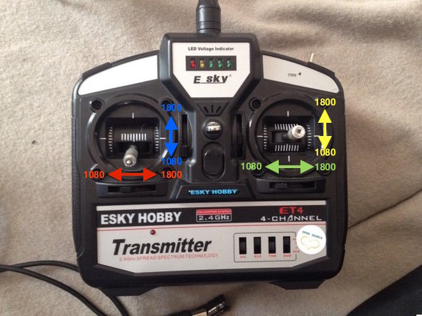
To do this, connect the receiver signal outputs (there are 4 of them, the top 2 are servo drives, the next 2 are for motor control) to the Arduino pin 5,6,7,8, one of the VCC inputs to 5v Arduino, and one of the GND inputs to GND arduino . With the help of the pulseIn () function, which reads the signal length at a given input, we get the values output by the receiver. Rejecting the levers as much as possible on the control panel, I fixed the values I needed. These are values from 1080 to 1800, with the values given out when the knobs are in normal condition for roll, pitch, and heading - 1,450, and for gas - 1,080.
The sketch is quite simple:
Well, actually it would seem that everything can be transferred to Arduino? Now we connect the motor controller (Arduino pin 5 and 6) and servos (Arduino pin 7 and 8) to the Arduino and write another sketch:
Fill, wait, and here the problems begin. First, it took a long time to think about why the controller turns on, but it cannot be calibrated and start working. After half an hour I found a solution: the problem was that it turned on and blinked at any voltage, but it only starts to work when using a battery with a minimum voltage of 7.4 Volts. In general, it even benefited, the Arduino is very well powered and runs from the battery through the controller, and you don’t have to put one battery on the control and the other on the motor controller managing a small capacity battery (850 mAh) and a voltage of 7.4V).
We connect the battery, try again. Again just blinks. It took about 3 hours to solve this problem. It turns out that in order for the controller to work, it needs to somehow interact with the receiver when it is turned on. How exactly, I have not yet managed to find out, perhaps the receiver sends some special values to it. To solve this, we also connect the receiver to the Arduino (Arduino pin 9,10,11,12), read the values from the console from it, and transfer them to the controller:
Fill, connect, work!
Now the receiver is connected to the controller via the Arduino, which intercepts the signal and sends it to the desired controller channel. Even though the signal changes (usually the value decreases by 15-20 units), the helicopter can even be lifted into the air.
Now add a button to the Arduino, when it is clamped, automatic control is activated.
Sketch:
To transfer control to the Arduino, you need to connect the battery, wait until the indicator on the controller starts to burn constantly, and then you can even turn off the receiver in principle, because after initialization, the controller can already work without a receiver.
In this example, using a cycle (for smooth servo travel) changes the angle of the blades. In the future, the same method will control the helicopter in flight.
Demonstration of work:
Since my plan does not have the construction of a full-fledged UAV, for the most part it is still a manually operated helicopter, and I will not completely remove the receiver from it. Therefore, it is necessary to somehow implement the communication between the Arduino, the radio receiver and the engine controller.
First of all, I decided to figure out how the receiver communicates with the controller. Once the servos are connected to the receiver as well as the controller, it means the principle of motor control is the same as the servos, which is based on PWM.
Then I decided to try to read the values from the receiver outputs.
')
Pin assignment on the receiver and motor controller: 1-GND, 2-VCC, 3-signal.
To do this, connect the receiver signal outputs (there are 4 of them, the top 2 are servo drives, the next 2 are for motor control) to the Arduino pin 5,6,7,8, one of the VCC inputs to 5v Arduino, and one of the GND inputs to GND arduino . With the help of the pulseIn () function, which reads the signal length at a given input, we get the values output by the receiver. Rejecting the levers as much as possible on the control panel, I fixed the values I needed. These are values from 1080 to 1800, with the values given out when the knobs are in normal condition for roll, pitch, and heading - 1,450, and for gas - 1,080.
The sketch is quite simple:
int c1; int c2; int c3; int c4; void setup() { pinMode(5, INPUT); pinMode(6, INPUT); pinMode(7, INPUT); pinMode(8,INPUT); Serial.begin(9600); } void loop() { c1 = pulseIn(5, HIGH, 25000); c2 = pulseIn(6, HIGH, 25000); c3 = pulseIn(7, HIGH, 25000); c4 = pulseIn(8, HIGH, 25000); Serial.print("C1:"); Serial.println(c1); Serial.print("C2:"); Serial.println(c2); Serial.print("C3:"); Serial.println(c3); Serial.print("C4:"); Serial.println(c4); } Well, actually it would seem that everything can be transferred to Arduino? Now we connect the motor controller (Arduino pin 5 and 6) and servos (Arduino pin 7 and 8) to the Arduino and write another sketch:
#include <Servo.h> Servo right; Servo left; Servo rightmot; Servo nizmot; int rightmot_pin = 5; int nizmot_pin = 6; int serv_left_pin=7; int serv_right_pin=8; int js_position = 800; int max_position = 3000; int spd1_now; void setup() { left.attach(serv_left_pin, js_position, max_position); right.attach(serv_right_pin, js_position, max_position); rightmot.attach(rightmot_pin, js_position, max_position); nizmot.attach(nizmot_pin, js_position, max_position); } void loop() { for(int i=1080,j=1800;i<1800,j>1080;i++,j--) { left.write(i); right.write(j); } for(int j=1800,i=1080;j>1080,i<1800;j--,i++) { left.write(j); right.write(i); } } Fill, wait, and here the problems begin. First, it took a long time to think about why the controller turns on, but it cannot be calibrated and start working. After half an hour I found a solution: the problem was that it turned on and blinked at any voltage, but it only starts to work when using a battery with a minimum voltage of 7.4 Volts. In general, it even benefited, the Arduino is very well powered and runs from the battery through the controller, and you don’t have to put one battery on the control and the other on the motor controller managing a small capacity battery (850 mAh) and a voltage of 7.4V).
We connect the battery, try again. Again just blinks. It took about 3 hours to solve this problem. It turns out that in order for the controller to work, it needs to somehow interact with the receiver when it is turned on. How exactly, I have not yet managed to find out, perhaps the receiver sends some special values to it. To solve this, we also connect the receiver to the Arduino (Arduino pin 9,10,11,12), read the values from the console from it, and transfer them to the controller:
#include <Servo.h> Servo right; Servo left; Servo rightmot; Servo nizmot; int rightmot_pin = 5; int nizmot_pin = 6; int serv_left_pin=7; int serv_right_pin=8; int js_position = 800; int max_position = 3000; int c1; int c2; int c3; int c4; int spd1_now; void setup() { pinMode(9, INPUT); pinMode(10, INPUT); pinMode(11, INPUT); pinMode(12,INPUT); left.attach(serv_left_pin, js_position, max_position); right.attach(serv_right_pin, js_position, max_position); rightmot.attach(rightmot_pin, js_position, max_position); nizmot.attach(nizmot_pin, js_position, max_position); } void loop() { c1 = pulseIn(5, HIGH, 25000); nizmot.write(c1); c2 = pulseIn(6, HIGH, 25000); rightmot.write(c2); c3 = pulseIn(7, HIGH, 25000); left.write(c3); c4 = pulseIn(8, HIGH, 25000); right.write(4); } Fill, connect, work!
Now the receiver is connected to the controller via the Arduino, which intercepts the signal and sends it to the desired controller channel. Even though the signal changes (usually the value decreases by 15-20 units), the helicopter can even be lifted into the air.
Now add a button to the Arduino, when it is clamped, automatic control is activated.
Sketch:
#include <Servo.h> Servo right; const int SEL = 2; // digital Servo left; Servo rightmot; Servo nizmot; int rightmot_pin = 5; int nizmot_pin = 6; int serv_left_pin=7; int serv_right_pin=8; int js_position = 800; int max_position = 3000; int c1; int c2; int c3; int c4; int spd1_now; void setup() { pinMode(SEL,INPUT); digitalWrite(SEL,HIGH); pinMode(9, INPUT); pinMode(10, INPUT); pinMode(11, INPUT); pinMode(12,INPUT); left.attach(serv_left_pin, js_position, max_position); right.attach(serv_right_pin, js_position, max_position); rightmot.attach(rightmot_pin, js_position, max_position); nizmot.attach(nizmot_pin, js_position, max_position); } void loop() { if(SEL == HIGH) { c1 = pulseIn(5, HIGH, 25000); nizmot.write(c1); c2 = pulseIn(6, HIGH, 25000); rightmot.write(c2); c3 = pulseIn(7, HIGH, 25000); left.write(c3); c4 = pulseIn(8, HIGH, 25000); right.write(4); } else { for(int i=1080,j=1800;i<1800,j>1080;i++,j--) { left.write(i); right.write(j); } for(int j=1800,i=1080;j>1080,i<1800;j--,i++) { left.write(j); right.write(i); } } } To transfer control to the Arduino, you need to connect the battery, wait until the indicator on the controller starts to burn constantly, and then you can even turn off the receiver in principle, because after initialization, the controller can already work without a receiver.
In this example, using a cycle (for smooth servo travel) changes the angle of the blades. In the future, the same method will control the helicopter in flight.
Demonstration of work:
Source: https://habr.com/ru/post/259683/
All Articles