Native OmniDirectional shadows implementation in DirectX11
Hey. Continuing to talk about various technologies from graphic game dev - I would like to talk about how to work with shadows in DirectX 11. I'll tell you about creating a Point-source of light with full use of GAPI DirectX11 tools, and will touch on such things as: Hardware Depth Bias , GS Cubemap Render , Native Shadow Map Depth , Hardware PCF .
Based on easy surfing on the Internet - I came to the conclusion that most of the articles on shadows in DX11 are incorrect, not very nicely implemented, or using outdated approaches. In this article I will try to compare the implementation of shadows in DirectX 9 and DirectX 11. Everything described below is also true for OpenGL.
Introduction
And for the start of this expedition, I will still bring into the business those people who do not quite understand what shadows are in games and how they work.
')
Even back in the 1978th year, Lance Williams introduced the concept of the method of creating shadows, which was called Projective shadowing (Shadow mapping) and for the state of 2015, there are no better shadow technologies available in production. Yes, there are a lot of modifications of Projective shadowing , but all of them, one way or another, are based on the latter. So what is the essence of this method and how can you get shadows from the geometry of any complexity, and even in real-time? The bottom line is that from the position of the light source the whole scene is rendered without textures and only the distance from the light source to a fragment of the scene is remembered, this thing is simply called the Shadow Map . This is done all before the main render of the scene. And further, in the simplest case - the main scene is drawn and for each fragment (pixel) of this scene it is determined whether the source sees this fragment (the light source can be called a camera) or not. If he sees - the light falls on a fragment, if he does not see - he does not hit, everything is simple. Well, I will say more about the mathematics of this process, almost all real-time rendering technologies are tied to matrices, I wrote about them a little bit here . The definition of the “visibility” of a scene fragment by a light source is as follows: the fragment position is converted from the space of the main camera (view matrix and projection of the main camera) into the light source space: as a result, two comparable values are obtained. The first is the distance from the center of the light source to a fragment of the scene, and the second is the same depth (distance) from the Shadow map that was created earlier. Comparing them - it is possible to determine whether the fragment is in the shadow or not.
Here is the simplest implementation of shadows. I also want to note that the sources of light are different, therefore, the shadows will also be different. There are four main types of light source:
- Spot Light (also known as Projection Light) - it is best presented as an ordinary projector, which has a cone angle of light and is directed to a specific place. The matrix of such a light source is Perspective Martix .
- Point Light (also known as Omnidirectional Light) is an omnidirectional light source, it is easier to imagine as a point (hence the Point), which emits light in all directions. The matrix of such a source is a Perspective Matrix with a viewing angle (Field of View, FOV) of 90 degrees, while it has six species matrices, which are directed to each side (the sides of the cube).
- Directional Light (also known as Sun Light) is an infinitely distant source of light, the sun on earth, for example. The matrix of such a light source is the Orthographic Matrix .
- Ambient Light is a special light source that has no position. Carries in itself information about the uniform light resulting from the reflections of light from other sources. In recent times, fading away and being replaced by advanced Global Illumination algorithms.
In theory, everything sounds good and consistent, but in practice there are some problems.
The first and most important problem is the discreteness of the shadow map. In GPU memory, they are stored as special format textures that have a finite size (in games, the “shadow quality” parameter is often associated with the size of the shadow map). You can present this problem if you place a small piece of geometry right in front of the light source and cast a shadow on the large canvas. Because of this, the distance between the ends of the beam and its beginning become incomparable (after all, shadow maps of finite size). The same pixel on the shadow map will correspond to many different positions on the canvas, this leads to such an effect as Aliasing (the shadow looks stepwise):

With this problem, there are many means of struggle, from non-standard projection matrices (for example, Trapezoidal Shadow Map , Geometry Pitch Shadow Map ) to the creation of a large number of shadow maps (4e: Cascaded Shadow Map ). But all these algorithms are rather narrow to use and are not universal. The most common way to get rid of strong aliasing is Percentage Closer Filtering , which is to make several samples with a certain constant offset and interpolate the data, but more about it later.
In this article I will consider one of the most difficult light sources - Omnidirectional Light . Since it radiates light in all directions and you have to make an unusual shadow map - Cube Shadow Map .
Let's start. What needs to be implemented for a point light source?
- Render scenes to a special shadow map - Cube Shadow Map
- Shader for rendering lighting for any model, for example Lambert
- DirectX11 shadow filtering
Shadow card render
In the era of DirectX9, there were few people who made honest point-light with shadows, but if they did, it was a great waste of resources. In order to calculate the shadow for an omnidirectional light source - it is necessary to show the world around the light source more than once, there are two options - either Dual Paraboloid Shadow Mapping (twice) or Cube Shadow Mapping (six times). Let us dwell on the second, because It is most traditional for point light. So, in the era of DirectX9, the world was rendered into a special cubic texture, which contained six two-dimensional textures in itself, each time it switched the active side (texture) and the world was drawn again. Unfortunately - many now continue to do the same, even on DirectX11. The second problem was that in DirectX9 it was impossible to work with hardware depth from the shader and had to write the depth for further use manually (often in a linear form).
In DirectX 9, the Cube Shadow Map worked as follows:
- The world was rendered six times - for each side separately
- The world was rendered in Render Target format R32_Float and was a normal texture
- Overwhelmingly, the depth of the fragments was recorded in a linear format.
- Shadows are manually filtered by overlaying.
Separately, I want to say why in a linear format? The fact is that in checking whether the shadow belongs to the current fragment, it was necessary to compare two values: the first is the depth recorded in the shadow map, and the second is the current depth of the fragment in the light source space. If everything was simple in the case of Spot / Directional, we took a point and reprojected this point into the light source space (by multiplying the view / projection of the light source by the matrix) and compared these two depths. In the case of Point-light, everything becomes more complicated, we have six different species matrices, which means that we must first determine which face the fragment is in and reproject with a specific face matrix. This meant that we had to use Dynamic Flow Control in the shader, which is pretty hard for the GPU. Therefore, they did it easier: they stored the depth in a linear format (the distance from the light source to the fragment was kept in the shadow map) and compared with the linear depth when superimposed. In this renderer, the hard depth buffer and the Render Target were used, where the linear depth was recorded.
In DirectX11, much has changed, at least with the advent of DirectX10, it became possible to use geometric shaders and read native depth in a shader.
How do the same shadows work in DirectX11?
- The world is rendered once - the geometry shader automatically selects the desired side for recording
- The approach no longer uses the Render Target and renders only the native depth to the hardware buffer.
- Fragment depth has a standard view: pz / pw
- Ability to use hardware PCF
Practice
Now, consider how it all looks in the implementation. The very first thing you need to implement Cube Shadows Mapping is a matrix of the form and projection:
_projection = Matrix.PerspectiveFovRH( MathUtil.DegreesToRadians(90.0f), 1.0f, 0.01f, this.Transform.Scale.X); The projection matrix always has a viewing angle of 90 degrees, the aspect ratio is one (the cube is still a cube), the far plane is equal to the radius of the light source.
There are six view matrices for this light source:
_view[0] = Matrix.LookAtRH(position, position + Vector3.Right, Vector3.Up); _view[1] = Matrix.LookAtRH(position, position + Vector3.Left, Vector3.Up); _view[2] = Matrix.LookAtRH(position, position + Vector3.Up, Vector3.BackwardRH); _view[3] = Matrix.LookAtRH(position, position + Vector3.Down, Vector3.ForwardRH); _view[4] = Matrix.LookAtRH(position, position + Vector3.BackwardLH, Vector3.Up); _view[5] = Matrix.LookAtRH(position, position + Vector3.ForwardLH, Vector3.Up); Each view matrix describes its own face. In DirectX11, the order of CubeTexture is: Right, Left, Up, Down, Front, Back.
The following is a special description of the Hardware Depth Buffer :
TextureDescription cubeDepthDescription = new TextureDescription() { ArraySize = 6, BindFlags = BindFlags.ShaderResource | BindFlags.DepthStencil, CpuAccessFlags = CpuAccessFlags.None, Depth = 1, Dimension = TextureDimension.TextureCube, Format = SharpDX.DXGI.Format.R32_Typeless, Height = CommonLight.SHADOW_CUBE_MAP_SIZE, MipLevels = 1, OptionFlags = ResourceOptionFlags.TextureCube, SampleDescription = new SharpDX.DXGI.SampleDescription(1, 0), Usage = ResourceUsage.Default, Width = CommonLight.SHADOW_CUBE_MAP_SIZE }; Bind flags are a shader resource and the fact that our texture is a depth buffer.
It is also important to cancel that the format is set to R32_Typeless , this is a mandatory requirement when reading hardware depth.
Due to the fact that we do not use the render to the texture - it is enough for us to fill the hardware depth buffer with data:
_graphics.SetViewport(0f, 0f, (float)CommonLight.SHADOW_CUBE_MAP_SIZE, (float)CommonLight.SHADOW_CUBE_MAP_SIZE); _graphics.SetRenderTargets((DepthStencilBuffer)light.ShadowMap); _graphics.Clear((DepthStencilBuffer)light.ShadowMap, SharpDX.Direct3D11.DepthStencilClearFlags.Depth, 1f, 0); _cubemapDepthResolver.Parameters["View"].SetValue(((OmnidirectionalLight)light).GetCubemapView()); _cubemapDepthResolver.Parameters["Projection"].SetValue(((OmnidirectionalLight)light).GetCubemapProjection()); scene.RenderScene(gameTime, _cubemapDepthResolver, false, 0); Set the size of the viewport, set the depth buffer, the effect and render our scene.
A standard shader needs only one thing - a vertex one, a pixel one is missing because, again, we don’t use Render To Texture :
VertexOutput DefaultVS(VertexInput input) { VertexOutput output = (VertexOutput)0; float4 worldPosition = mul(input.Position, World); output.Position = worldPosition; return output; } Just here another shader appears - a geometric one, it will then choose the necessary face for recording the depth:
[maxvertexcount(18)] void DefaultGS( triangle VertexOutput input[3], inout TriangleStream<GeometryOutput> CubeMapStream ) { [unroll] for( int f = 0; f < 6; ++f ) { { GeometryOutput output = (GeometryOutput)0; output.RTIndex = f; [unroll] for( int v = 0; v < 3; ++v ) { float4 worldPosition = input[v].Position; float4 viewPosition = mul(worldPosition, View[f]); output.Position = mul(viewPosition, Projection); CubeMapStream.Append( output ); } CubeMapStream.RestartStrip(); } } } His task is to receive a triangle at the entrance, and in response to emit six, but each will be in his face (the parameter RTIndex). Here are the structures:
cbuffer Params : register(b0) { float4x4 World; float4x4 View[6]; float4x4 Projection; }; struct VertexInput { float4 Position : SV_POSITION; //uint InstanceID : SV_InstanceID; }; struct VertexOutput { float4 Position : SV_POSITION; //uint InstanceID : SV_InstanceID; }; struct GeometryOutput { float4 Position : SV_POSITION; uint RTIndex : SV_RenderTargetArrayIndex; }; A person who worked with multiple renders of the same model may notice that instead of emite of a new geometry, you can use instancing by choosing the desired RTIndex based on InstanceID. Yes, you can, but I got a noticeable loss in performance. In detail, why it happened - did not go. It turned out to be much easier to simulate new triangles than to use the ones obtained from the instancing.
After this process, we can get hard cubic depth. In this case, the render of this geometry was made in one pass.
The next stage is the imposition of a shadow, in my example Deferred Shading is used , but this is also true for Forward rendering. Now again about the problems: we have to translate the distance from the light source to the fragment into the light source space (cubic depth buffer), but we simply cannot do this, because it is necessary to know which of the six species matrices to use. You don’t want to use Dynamic Flow Control , so you can come up with an interesting hack, which is based on the fact that all view matrices are the same and have a FOV of 90 degrees:
float _vectorToDepth(float3 vec, float n, float f) { float3 AbsVec = abs(vec); float LocalZcomp = max(AbsVec.x, max(AbsVec.y, AbsVec.z)); float NormZComp = (f+n) / (fn) - (2*f*n)/(fn)/LocalZcomp; return (NormZComp + 1.0) * 0.5; } In this way, we can determine the depth in the light source space of a particular vector.
Now, we can read the depth from the shadow map using the three-dimensional vector [FragmentPosition-LightPosition] and obtain the depth in the light source space using the same vector, compare them and determine whether the fragment is in the shadow or not.
After passing the shaders to get the shadow and rendering the Light card, we get a shadow with strong aliasing. For this, the shadow would be good to handle with a filter and the DirectX11 Hardware PCF comes to the rescue, this feature is realized by using special comprasion samplers:
SamplerComparisonState LightCubeShadowComparsionSampler : register(s0); It is described as follows:
var dms4 = SharpDX.Direct3D11.SamplerStateDescription.Default(); dms4.AddressU = SharpDX.Direct3D11.TextureAddressMode.Clamp; dms4.AddressV = SharpDX.Direct3D11.TextureAddressMode.Clamp; dms4.Filter = SharpDX.Direct3D11.Filter.ComparisonMinMagMipLinear; dms4.ComparisonFunction = SharpDX.Direct3D11.Comparison.Less; And a sample is made like this:
LightCubeShadowMap.SampleCmpLevelZero(LightCubeShadowComparsionSampler, lightVector, obtainedDepth).r Where obtainedDepth is the depth that is obtained from the _vectorToDepth function.
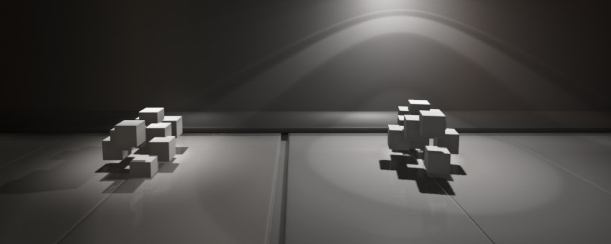
The output is a smoothed depth comparison result (if the sampler filter was Linear), which is equivalent to 2x2 Bilinear PCF:

You can also make an additional 3x3 HPCF and get the following result:

I completely forgot to mention one more problem: as mentioned earlier, the depth buffer is discrete, which means that any surface reflected in this buffer looks intermittent (due to limited accuracy), like this:

The surface begins to cast a shadow on itself, creating the wrong shadow:

This problem is solved if, when comparing, one of the depths is shifted by some small value (bias) in order to even out the problem. Usually they do something like: cD + 0.0001 <sD when checking. This method is harmful, because shifting in this way - we very easily get the effect of Peter Pan:
Peter Pan
To effectively solve the problem in DirectX11 there are standard tools, these bias values are set in Rasterizer State , the DepthBias and SlopeScaledDepthBias parameters .
Smooth point-light shadows using DirectX11 features are implemented in such a simple way.
I will not post the full code, because it is very much connected with the engine, but I’m sure to share the shaders:
DeferredShading.fx#include "..//pp_GBuffer.fxh" #include "Lights.fxh" float4 PointLightPS(float2 UV : TEXCOORD) : SV_TARGET { SurfaceData surfaceData = GetSurfaceData(UV); float3 texelPosition = GetPosition(UV); float3 texelNormal = surfaceData.Normal; float3 vL = texelPosition - LightPosition; float3 L = normalize(vL); float3 lightColor = _calculationLight(texelNormal, L); float3 lightCookie = float3(1, 1, 1); if(IsLightCookie) { float3 rL = mul(float4(L, 1), LightRotation).xyz; lightCookie = LightCubeCookie.Sample(LightCubeCookieSampler, float3(rL.xy, -rL.z) ).rgb; } float shadowed = 1; if(IsLightShadow) shadowed = _sampleCubeShadowHPCF(L, vL); //if(IsLightShadow) // shadowed = _sampleCubeShadowPCFSwizzle3x3(L, vL); float atten = _calcAtten(vL); return float4(lightColor * lightCookie * shadowed * atten, 1); } technique PointLightTechnique { pass { Profile = 10.0; PixelShader = PointLightPS; } }Lights.fxhcbuffer LightSource : register(b1) { float3 LightPosition; float LightRadius; float4 LightColor; float4x4 LightRotation; float2 LightNearFar; const bool IsLightCookie; const bool IsLightShadow; }; TextureCube<float4> LightCubeCookie : register(t3); SamplerState LightCubeCookieSampler : register(s1); TextureCube<float> LightCubeShadowMap : register(t4); SamplerComparisonState LightCubeShadowComparsionSampler : register(s2); SamplerState LightCubeShadowPointSampler : register(s3); float _calcAtten(float3 vL) { float3 lVec = vL / LightRadius; return max(0.0, 1.0 - dot(lVec,lVec)); } float3 _calculationLight(float3 N, float3 L) { return LightColor.xyz * saturate(dot(N, -L)) * LightColor.w; } float _vectorToDepth(float3 vec, float n, float f) { float3 AbsVec = abs(vec); float LocalZcomp = max(AbsVec.x, max(AbsVec.y, AbsVec.z)); float NormZComp = (f+n) / (fn) - (2*f*n)/(fn)/LocalZcomp; return (NormZComp + 1.0) * 0.5; } float _sampleCubeShadowHPCF(float3 L, float3 vL) { float sD = _vectorToDepth(vL, LightNearFar.x, LightNearFar.y); return LightCubeShadowMap.SampleCmpLevelZero(LightCubeShadowComparsionSampler, float3(L.xy, -Lz), sD).r; } float _sampleCubeShadowPCFSwizzle3x3(float3 L, float3 vL) { float sD = _vectorToDepth(vL, LightNearFar.x, LightNearFar.y); float3 forward = float3(L.xy, -Lz); float3 right = float3( forward.z, -forward.x, forward.y ); right -= forward * dot( right, forward ); right = normalize(right); float3 up = cross(right, forward ); float tapoffset = (1.0f / 512.0f); right *= tapoffset; up *= tapoffset; float3 v0; v0.x = LightCubeShadowMap.SampleCmpLevelZero(LightCubeShadowComparsionSampler, forward - right - up, sD).r; v0.y = LightCubeShadowMap.SampleCmpLevelZero(LightCubeShadowComparsionSampler, forward - up, sD).r; v0.z = LightCubeShadowMap.SampleCmpLevelZero(LightCubeShadowComparsionSampler, forward + right - up, sD).r; float3 v1; v1.x = LightCubeShadowMap.SampleCmpLevelZero(LightCubeShadowComparsionSampler, forward - right, sD).r; v1.y = LightCubeShadowMap.SampleCmpLevelZero(LightCubeShadowComparsionSampler, forward, sD).r; v1.z = LightCubeShadowMap.SampleCmpLevelZero(LightCubeShadowComparsionSampler, forward + right, sD).r; float3 v2; v2.x = LightCubeShadowMap.SampleCmpLevelZero(LightCubeShadowComparsionSampler, forward - right + up, sD).r; v2.y = LightCubeShadowMap.SampleCmpLevelZero(LightCubeShadowComparsionSampler, forward + up, sD).r; v2.z = LightCubeShadowMap.SampleCmpLevelZero(LightCubeShadowComparsionSampler, forward + right + up, sD).r; return dot(v0 + v1 + v2, .1111111f); } // UE4: https://github.com/EpicGames/UnrealEngine/blob/release/Engine/Shaders/ShadowProjectionCommon.usf static const float2 DiscSamples5[]= { // 5 random points in disc with radius 2.500000 float2(0.000000, 2.500000), float2(2.377641, 0.772542), float2(1.469463, -2.022543), float2(-1.469463, -2.022542), float2(-2.377641, 0.772543), }; float _sampleCubeShadowPCFDisc5(float3 L, float3 vL) { float3 SideVector = normalize(cross(L, float3(0, 0, 1))); float3 UpVector = cross(SideVector, L); SideVector *= 1.0 / 512.0; UpVector *= 1.0 / 512.0; float sD = _vectorToDepth(vL, LightNearFar.x, LightNearFar.y); float3 nlV = float3(L.xy, -Lz); float totalShadow = 0; [UNROLL] for(int i = 0; i < 5; ++i) { float3 SamplePos = nlV + SideVector * DiscSamples5[i].x + UpVector * DiscSamples5[i].y; totalShadow += LightCubeShadowMap.SampleCmpLevelZero( LightCubeShadowComparsionSampler, SamplePos, sD); } totalShadow /= 5; return totalShadow; }CubeDepthReslover.fxhcbuffer Params : register(b0) { float4x4 World; float4x4 View[6]; float4x4 Projection; }; struct VertexInput { float4 Position : SV_POSITION; //uint InstanceID : SV_InstanceID; }; struct VertexOutput { float4 Position : SV_POSITION; //uint InstanceID : SV_InstanceID; }; struct GeometryOutput { float4 Position : SV_POSITION; uint RTIndex : SV_RenderTargetArrayIndex; }; VertexOutput DefaultVS(VertexInput input) { VertexOutput output = (VertexOutput)0; float4 worldPosition = mul(input.Position, World); output.Position = worldPosition; //output.InstanceID = input.InstanceID; return output; } [maxvertexcount(18)] void DefaultGS( triangle VertexOutput input[3], inout TriangleStream<GeometryOutput> CubeMapStream ) { [unroll] for( int f = 0; f < 6; ++f ) { { GeometryOutput output = (GeometryOutput)0; output.RTIndex = f; [unroll] for( int v = 0; v < 3; ++v ) { float4 worldPosition = input[v].Position; float4 viewPosition = mul(worldPosition, View[f]); output.Position = mul(viewPosition, Projection); CubeMapStream.Append( output ); } CubeMapStream.RestartStrip(); } } } technique CubeDepthResolver { pass DefaultPass { Profile = 10.0; VertexShader = DefaultVS; GeometryShader = DefaultGS; PixelShader = null; } }
If you have any questions or need help - I will be happy to help, you can see the contacts in my profile.
Coming upcoming articles:
- Implement Deferred Rendered Water
- Physically-Based Rendering without using IBL
PS
Dear reader, if you like to read the articles carefully and have found something inaccurate or inaccurate, do not rush to write a comment, but rather write me a personal message, I will definitely say thank you!
Source: https://habr.com/ru/post/259679/
All Articles