"1-wire" for buttons with indication
I somehow conceived to apply such a button with a status indication in one of the constructions:
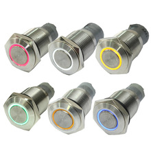
Inside - a pair of closing or switching contacts and an LED (optionally - already with a damping resistor to choose from for power supply from 5, 12, or 24 V). Everything would be fine with it, but I planned to place the button on the car dashboard, and the control unit - in the engine compartment. And I didn’t really want to pull individual wires for contact and for indication.
')
How to solve it, and what is needed for this - under the cut
As a result, this decision came to mind:

Will work with ports of explosives of the microcontroller, for which there are:
a) bidirectional mode
b) a safe limit on the output current (in the STM32 EMNIP is regulated by software)
c) a virtual port that allows you to read the signal directly from the pins (in AVR PINx)
The algorithm is as follows:
1. periodically check the port PIN bit to which the button is connected (for example, once every 20 ms)
1a at the time of the check, if the output PORT was equal to 0, we set it to 1 (the check itself — a few microseconds — is not noticeable with the eye)
2. if the PIN is found to be 0, then the button is pressed - we remember the fact of primary detection (for the anti-debugging algorithm)
2a. if at the same time there was a high level on the PORT and we found a click, we remove it until periodic check of item 1 shows a steady release of the button (3-5 consecutive checks) - since the LED will not glow due to shunting anyway contacts of the button, and to reduce the output current through the port, limited at the push of a button only by the output stage, is very useful in all senses
3. if you confirmed pressing or releasing for several verification cycles - we process it in the program, and light the LED through PORT, respectively
The disadvantage of such an inclusion is that the indicator will be extinguished during the whole time the button is held by the person - that is, if the toggle switch is implemented, then the transition from on to off visually occurs at the moment of pressing, and from off to on - at the moment of releasing - this can not quite comfortable
Now for MCs that do not know how to track the status of the port pins directly, or do not have the means to limit the output current (for example, the old 8051 families and their clones):

Here you will have to sacrifice another line of explosives tuned to the input, and divide the damping resistor into two parts. In this case, the algorithm remains the same, unless it is necessary to transfer the output port to 0 for as long as a button is pressed, but it is still desirable for autonomous systems from the point of view of reducing the consumed current. The proportion of resistor values can be chosen and not so extreme (putting the output to earth through 39 Ohms, even for milliseconds, may be harsh for some MCs) - it’s only important that the voltage drop across the LED + its lower half of the limiting resistor at a high output port level more stock than Vcc / 2
And finally, a variant of the scheme for several buttons with an indication - here you can use one input line for all, unleashing diodes:

The input port pull-up (drawn with a dotted line on the right) to exclude the weak illumination of the buttons through decoupling diodes can be turned on only at the moment of scanning the state. Scan multiple buttons naturally by turns.
Here's an idea - in practice, the truth has not yet managed to check, even drew only on a piece of paper
Inside - a pair of closing or switching contacts and an LED (optionally - already with a damping resistor to choose from for power supply from 5, 12, or 24 V). Everything would be fine with it, but I planned to place the button on the car dashboard, and the control unit - in the engine compartment. And I didn’t really want to pull individual wires for contact and for indication.
')
How to solve it, and what is needed for this - under the cut
As a result, this decision came to mind:
Will work with ports of explosives of the microcontroller, for which there are:
a) bidirectional mode
b) a safe limit on the output current (in the STM32 EMNIP is regulated by software)
c) a virtual port that allows you to read the signal directly from the pins (in AVR PINx)
The algorithm is as follows:
1. periodically check the port PIN bit to which the button is connected (for example, once every 20 ms)
1a at the time of the check, if the output PORT was equal to 0, we set it to 1 (the check itself — a few microseconds — is not noticeable with the eye)
2. if the PIN is found to be 0, then the button is pressed - we remember the fact of primary detection (for the anti-debugging algorithm)
2a. if at the same time there was a high level on the PORT and we found a click, we remove it until periodic check of item 1 shows a steady release of the button (3-5 consecutive checks) - since the LED will not glow due to shunting anyway contacts of the button, and to reduce the output current through the port, limited at the push of a button only by the output stage, is very useful in all senses
3. if you confirmed pressing or releasing for several verification cycles - we process it in the program, and light the LED through PORT, respectively
The disadvantage of such an inclusion is that the indicator will be extinguished during the whole time the button is held by the person - that is, if the toggle switch is implemented, then the transition from on to off visually occurs at the moment of pressing, and from off to on - at the moment of releasing - this can not quite comfortable
Now for MCs that do not know how to track the status of the port pins directly, or do not have the means to limit the output current (for example, the old 8051 families and their clones):
Here you will have to sacrifice another line of explosives tuned to the input, and divide the damping resistor into two parts. In this case, the algorithm remains the same, unless it is necessary to transfer the output port to 0 for as long as a button is pressed, but it is still desirable for autonomous systems from the point of view of reducing the consumed current. The proportion of resistor values can be chosen and not so extreme (putting the output to earth through 39 Ohms, even for milliseconds, may be harsh for some MCs) - it’s only important that the voltage drop across the LED + its lower half of the limiting resistor at a high output port level more stock than Vcc / 2
And finally, a variant of the scheme for several buttons with an indication - here you can use one input line for all, unleashing diodes:
The input port pull-up (drawn with a dotted line on the right) to exclude the weak illumination of the buttons through decoupling diodes can be turned on only at the moment of scanning the state. Scan multiple buttons naturally by turns.
Here's an idea - in practice, the truth has not yet managed to check, even drew only on a piece of paper
Source: https://habr.com/ru/post/259621/
All Articles