Controlling the volume of a multi-zone amplifier with an Android and Arduino application

First of all, I would like to thank 470 readers who voted for the continuation in the article about a multi-zone amplifier.
Operation of the amplifier showed that it is not very convenient to adjust the volume while being in a room that can be far enough away from the storage room where the amplifier is located with volume controls. We have to run a few times to the pantry and back to achieve the desired volume level.
Thus was born the idea of a regulator, which is always with you in your pocket, i.e. phone applications that can control the amplifier via a Wi-Fi network.
')
To implement digital control of the amplifier volume level, the mechanical potentiometer will be replaced by an electronic one (DPOT - Digital Potentiometer). Among the not very wide variety of available DPOT, the MCP41050 was chosen with a nominal value of 50 kΩ, which corresponds to the nominal value of the replaced mechanical analogue.
This is a single-channel potentiometer, therefore, for 1 stereo amplifier you will need 2 pieces. There are also dual versions of the same series (MCP42XXX), but it was technologically more convenient for me to use 2 separate ones. Consider briefly how it works.
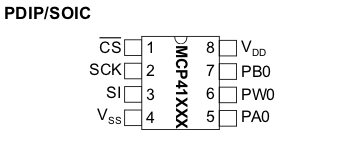
The analog part is represented by pins 5-7, pin 6 (PW0) is the engine (Wiper) of the potentiometer. Control is done through the SPI (Serial Peripheral Interface) (pins 1-3). 5V power is supplied to the Vss and Vdd terminals. Chip programming involves sequentially sending the Command Byte and Data Byte setting the position of the potentiometer slider to the 0-255 position.
Finalization of the amplifier.
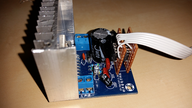
As I told in the previous article, I chose the cheapest of the ready-made amps for $ 2.7 and I did not feel sorry for killing it for the sake of the experiment. To begin, remove (carefully dispense) the mechanical potentiometer as shown in the picture:
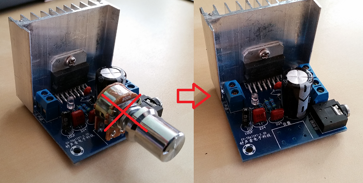
In the vacant space will be installed our dual electronic controller.
Regulator assembly.
Cut the breadboard along and then across 3 parts as shown in the picture:
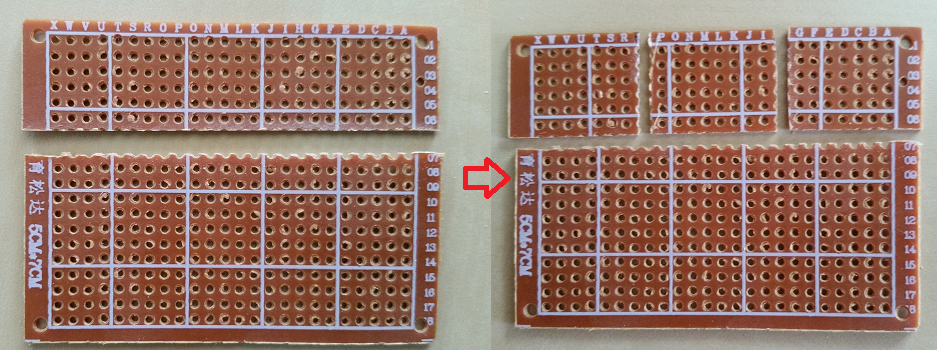
If you hold a sharp knife along the holes a couple of times, the board is easily broken by hand like a cookie. After that, you need a file to slightly trim the edges. From the resulting pieces we will need 2 small ones, they are approximately 1.5 x 2 cm in size.
Conclusions 2-4, 8 chips are connected in parallel, so it is convenient to assemble both boards in the form of a sandwich:
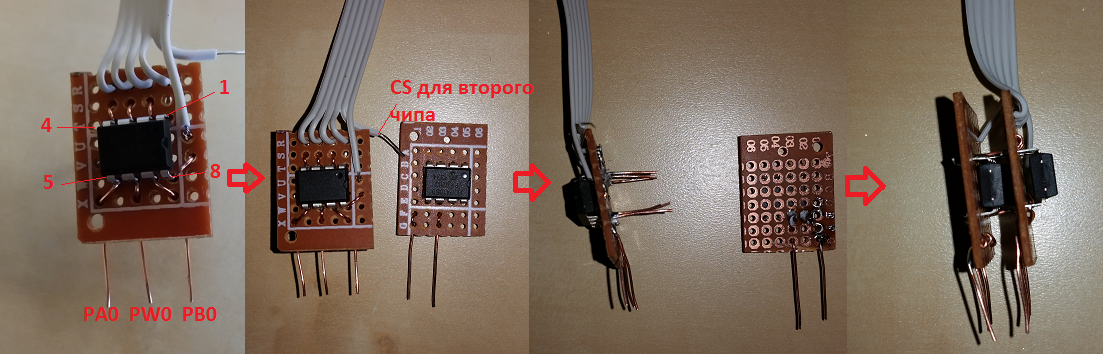
To connect the control circuit and power supply with the Arduino board, we use a piece of cable-loop. At the same time, digital control lines are located away from analog circuits in order to avoid interference.
After pre-testing, the assembled regulator is soldered to the amplifier:
As shown by testing, adding DPOT with digital control circuits to the input circuits of the amplifier did not lead to noticeable noises or interferences.
Circuit diagram

Program for Arduino.
The management method “SPI by hand” (“SPI by Hand”) described here is based on the little-scale.blogspot.it/2007/07/spi-by-hand.html . It features 2 functions.
The spi_transfer function sends a byte to the chip bit by bit.
void spi_transfer(byte working) { for(int i = 1; i <= 8; i++) // Set up a loop of 8 iterations (8 bits in a byte) { if (working > 127) { digitalWrite (POT_MOSI,HIGH) ; } // If the MSB is a 1 then set MOSI high else { digitalWrite (POT_MOSI, LOW) ; } // If the MSB is a 0 then set MOSI low digitalWrite (CLKdpot,HIGH) ; // Pulse the CLKdpot high working = working << 1 ; // Bit-shift the working byte digitalWrite(CLKdpot,LOW) ; // Pulse the CLKdpot low } } The function spi_out sends the command and data bytes to the chip which is selected by setting the logical line CS to 0.
void spi_out(int CS, byte cmd_byte, byte data_byte) { digitalWrite (CS, LOW); // Set the passed ChipSelect pin to low to start programming spi_transfer(cmd_byte); // Send the passed COMMAND BYTE delay(2); spi_transfer(data_byte); // Send the passed DATA BYTE delay(2); digitalWrite(CS, HIGH); // Set the passed ChipSelect pin to high to end programming } Since it was decided to implement the control over the local network, and not via Bluetooth, the Ethernet shield, Web server was included in the standard connection in the circuit. Running a little ahead, it should be noted that the program for the phone was created in the MIT App Inventor for which there is no TCP client implementation. Therefore, the management had to be done by sending commands in the GET request parameters.
After selecting the commands (param) and values (value) from the query string, they are sent to control our DPOTs:
param = readString.substring(6,9); value = readString.substring(10,13).toInt(); if (param=="V1L") {V1L=value; spi_out(CS1, cmd_byte, V1L);} if (param=="V1R") {V1R=value; spi_out(CS2, cmd_byte, V1R);} if (param=="MU1") {spi_out(CS1, cmd_byte, V1L/5); spi_out(CS2, cmd_byte, V1R/5);} if (param=="UM1") {spi_out(CS1, cmd_byte, V1L); spi_out(CS2, cmd_byte, V1R);} Commands V1L, V1R - set the volume of the first left / right channel corresponding to the value value which can be equal to 0 - 255.
Commands MU1, UM1 - Mute, Unmute. Temporary mute (source level / 5) and return the volume to the original value.
Sketch the whole
#include <UIPEthernet.h> #include <String.h> int CS1 = 19; // Chip Select int CS2 = 18; int CS3 = 17; int CS4 = 16; int CS5 = 15; int CS6 = 14; int CS7 = 8; int CS8 = 7; int CLKdpot = 4; // Clock pin 4 arduino int POT_MOSI = 5; // MOSI pin 5 arduino byte cmd_byte = B00010011 ; // Command byte 'write' data to POT uint8_t POTposition1 = 10; //initialize DPOT set initial position uint8_t POTposition2 = 10; uint8_t POTposition3 = 10; uint8_t POTposition4 = 10; uint8_t POTposition5 = 10; uint8_t POTposition6 = 10; uint8_t POTposition7 = 10; uint8_t POTposition8 = 10; uint8_t mac[6] = {0x00,0x01,0x02,0x03,0x04,0x05}; uint8_t ip[4] = {192, 168, 6, 25}; // IP address for the webserver uint16_t port = 80; // Use port 80 - the standard for HTTP EthernetServer server(80); String readString = String(100); String param = String(3); int value = 0; int V1L = 0; int V1R = 0; int V2L = 0; int V2R = 0; int V3L = 0; int V3R = 0; int V4L = 0; int V4R = 0; void spi_transfer(byte working) { for(int i = 1; i <= 8; i++) // Set up a loop of 8 iterations (8 bits in a byte) { if (working > 127) { digitalWrite (POT_MOSI,HIGH) ; } // If the MSB is a 1 then set MOSI high else { digitalWrite (POT_MOSI, LOW) ; } // If the MSB is a 0 then set MOSI low digitalWrite (CLKdpot,HIGH) ; // Pulse the CLKdpot high working = working << 1 ; // Bit-shift the working byte digitalWrite(CLKdpot,LOW) ; // Pulse the CLKdpot low } } void spi_out(int CS, byte cmd_byte, byte data_byte) { digitalWrite (CS, LOW); // Set the passed ChipSelect pin to low to start programming spi_transfer(cmd_byte); // Send the passed COMMAND BYTE delay(2); spi_transfer(data_byte); // Send the passed DATA BYTE delay(2); digitalWrite(CS, HIGH); // Set the passed ChipSelect pin to high to end programming } void setup() { Serial.begin(9600); pinMode (CS1, OUTPUT); pinMode (CS2, OUTPUT); pinMode (CS3, OUTPUT); pinMode (CS4, OUTPUT); pinMode (CS5, OUTPUT); pinMode (CS6, OUTPUT); pinMode (CS7, OUTPUT); pinMode (CS8, OUTPUT); pinMode (CLKdpot, OUTPUT); pinMode (POT_MOSI, OUTPUT); spi_out(CS1, cmd_byte, POTposition1); spi_out(CS2, cmd_byte, POTposition2); spi_out(CS3, cmd_byte, POTposition3); spi_out(CS4, cmd_byte, POTposition4); spi_out(CS5, cmd_byte, POTposition5); spi_out(CS6, cmd_byte, POTposition6); spi_out(CS7, cmd_byte, POTposition7); spi_out(CS8, cmd_byte, POTposition8); // start the Ethernet connection and the server: Ethernet.begin(mac, ip); server.begin(); Serial.print("server is at "); Serial.println(Ethernet.localIP()); } void loop() { // listen for incoming clients readString=""; EthernetClient client = server.available(); if (client) { Serial.println("new client"); // an http request ends with a blank line boolean currentLineIsBlank = true; while (client.connected()) { if (client.available()) { char c = client.read(); size_t pos = 0; if (readString.length() < 16) { //store characters to string readString +=c; } // if you've gotten to the end of the line (received a newline // character) and the line is blank, the http request has ended, // so you can send a reply if (c == '\n' && currentLineIsBlank) { // send a standard http response header client.println("HTTP/1.1 200 OK"); client.println("Content-Type: text/html"); client.println("Connection: close"); client.println(); client.println("<!DOCTYPE HTML>"); client.println("<html>"); client.println("</html>"); break; } if (c == '\n') { // you're starting a new line currentLineIsBlank = true; } else if (c != '\r') { // you've gotten a character on the current line currentLineIsBlank = false; } } } // give the web browser time to receive the data delay(1); // close the connection: client.stop(); Serial.println("client disconnected"); Serial.println(readString); param = readString.substring(6,9); value = readString.substring(10,13).toInt(); Serial.println(param); Serial.println(value); if (param=="V1L") {V1L=value; spi_out(CS1, cmd_byte, V1L);} if (param=="V1R") {V1R=value; spi_out(CS2, cmd_byte, V1R);} if (param=="V2L") {V2L=value; spi_out(CS3, cmd_byte, V2L);} if (param=="V2R") {V2R=value; spi_out(CS4, cmd_byte, V2R);} if (param=="V3L") {V3L=value; spi_out(CS5, cmd_byte, V3L);} if (param=="V3R") {V3R=value; spi_out(CS6, cmd_byte, V3R);} if (param=="V4L") {V4L=value; spi_out(CS7, cmd_byte, V4L);} if (param=="V4R") {V4R=value; spi_out(CS8, cmd_byte, V4R);} if (param=="MU1") { spi_out(CS1, cmd_byte, V1L/5); spi_out(CS2, cmd_byte, V1R/5); spi_out(CS3, cmd_byte, V2L/5); spi_out(CS4, cmd_byte, V2R/5); spi_out(CS5, cmd_byte, V3L/5); spi_out(CS6, cmd_byte, V3R/5); spi_out(CS7, cmd_byte, V4L/5); spi_out(CS8, cmd_byte, V4R/5); } if (param=="UM1") { spi_out(CS1, cmd_byte, V1L); spi_out(CS2, cmd_byte, V1R); spi_out(CS3, cmd_byte, V2L); spi_out(CS4, cmd_byte, V2R); spi_out(CS5, cmd_byte, V3L); spi_out(CS6, cmd_byte, V3R); spi_out(CS7, cmd_byte, V4L); spi_out(CS8, cmd_byte, V4R); } } } “Volume Control” app for Android.
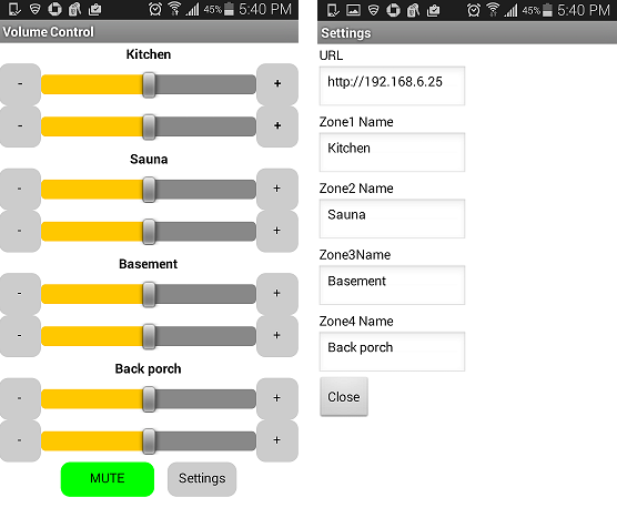
The application is created using the MIT App Inventor tool. The application has 2 screens: the main screen and the settings screen. The main screen includes 4 identical sections, one per zone. The settings screen contains controls for setting the URL to the corresponding IP address of the Arduino, as well as the names of the zones.
A few details explaining the program.
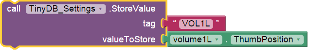
The values of the settings and the position of the volume controls are stored in TinyDB and are used when the application is initialized when it is opened. An example of saving the value of the level of the left channel of the first zone when closing an application:
As mentioned above, the WebViewer component is used to send commands using the Get method as part of a request to a web server running on the Arduino.
Sending commands as a frequently repeated operation is highlighted in the SendCommand procedure.
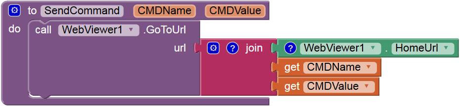
For example, when changing the position of the left channel regulator of the first zone, it will be called as
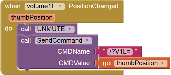
A request of the form http://192.168.6.25/?V1L=156 will be sent.
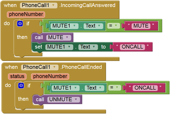
If the application is running on a smartphone, then the sound can be automatically muted when answering a call and restored when it ends:
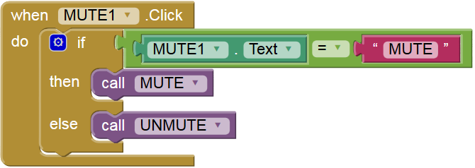
When you click on the “Mute” button, the Mute procedure is called which in turn calls SendCommand and changes the color and name of the button:
The project file for App Inventor 2 will send to those who wish on request.
In conclusion, I provide a video demonstrating the operation of the application. The delay in switching the screen is due to the fact that the application is running in MIT AI2 Companion.
Source: https://habr.com/ru/post/259579/
All Articles