Creating plug-ins for AutoCAD using the .NET API (Part 5 - Introduction to Blocks)
In the fifth part of the cycle devoted to the development of plug-ins under AutoCAD, I will tell you about creating simple blocks and placing them in a drawing.
If, when working with a drawing, it becomes necessary to create objects of the same type, then it is best to do this using the mechanism of blocks — named groups of objects that behave as a single object. General information about the blocks can be found here .
It is important to be able to clearly distinguish between two concepts: the definition of a block and the occurrence of a block . A detailed description of the differences is given here (English) and here (rus). Briefly set out the essence: when we create a new block, AutoCAD places its description in a special block table. This description is called a block definition . The block definition exists exclusively in the block table and is not displayed in the drawing. Directly on the drawing field, AutoCAD places a block reference entry — a link to the block definition. When the block definition is changed, all occurrences of the block repeat these changes. Further in the article I will sometimes omit the first word (“definition” or “entry”) and write simply “block”.
')
In the process of communicating with Autocad, I came across two types of blocks: normal and dynamic . The main feature of the second is the ability to set their elements with some “customizable” parameters (for example, the length of a line in a block or its angle of inclination). The main disadvantage of dynamic blocks is that they cannot be created using the .NET API.
I will tell about dynamic blocks another time. In the meantime, let's see how you can work with ordinary blocks.
To begin, let's create a block directly in AutoCAD. There will be no programming here - but the ability to create a block manually is useful in order to be able to at least approximately estimate the result of the plug-in. Details of the process - under the spoiler.
This section is based on the corresponding post on the Kean Walmsley blog (our example compared to the original source will be much easier). We will create the simplest block consisting of a polyline, a circle and a block of text.
To create a block and place its entry on a drawing, you must do the following:
So let's get started.
I will no longer dwell on such minor features of creating a plug-in as connecting external links, banning
Now let's understand what happens in the code.
First, we carry out preparatory operations: we obtain references to the document, its database and the
I could not find detailed information on the
Inside the transaction, we act on the algorithm outlined at the beginning of this subsection.
In the first step, we create a new entry in the block table, for which:
In the second step, we add the necessary geometric primitives to the created record. We will have three of them: a polyline, a circle and a text.
Adding a polyline and a circle to a drawing was explained in the previous article; with the text everything happens in a similar way. Adding a graphic object to a block usually takes place in three steps:
This applies to both the polyline and the circle, and to the text. What part of the code is responsible for which item is quite obvious. You can read more about adding text to a drawing here (English) and here (rus).
In the third step, we add the occurrence of the created block to the drawing. The procedure here is:
Let us dwell a little bit more on the constructor of the
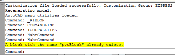
If in the previous example execute the HabrCommand command, then remove the appeared block from the drawing and execute the HabrCommand again, we will see the message “A block with the name„ pvtBlock “already exists”, and nothing will appear on the drawing. To use a previously created block definition, you need to know the
If we now execute the HabrCommand command, then remove the block that appears from the drawing and rerun the HabrCommand command, the occurrence of our block will reappear on the drawing. In this case, a new block definition will not be created - the plugin will take the record that already exists in the block table.
In the
If in the first example we immediately opened the block table for writing (
Where the block will appear in the drawing, itis impossible to predict in advance it depends on two things:
In our example, the base point is located in the center of the block.
Note that when creating a block definition, we never set the base point anywhere explicitly - in such a case, AutoCAD assumes that the base point is the origin. In our example, the "center" of the shape was specially selected so that it coincided with the center of coordinates.
You can manually change the base definition point of a block using the block editor (as described in the first section of the post) or using the .NET API. In the latter case, the
The numbers -50 and -125 are the minimum coordinates of our block along the X and Y axes, respectively (such coordinates are the lower left vertex of the polyline, which forms the outer boundary of our block).
Now let's deal with the insertion point of the block. It is set for each block entry and shows where its base point will be after inserting the block. This property is set in the class constructor
The block insertion point can also be changed using the
The effect will be the same as when defining a point directly in the class constructor
We all love blocks here, so let's add a couple of blocks to our block to simplify the drawing, while we simplify the drawing.
Adding a block to a block definition is easy. The main feature is that if we add not a geometric primitive to the block, but an entry of an auxiliary block, then we definitely need to ensure that the definition of this auxiliary block is in the table of document blocks.
By and large, there is nothing to comment here: we simply add a definition of an auxiliary block to the block table, and then create an entry for the auxiliary block and give it the coordinates of the insertion point.
As a simple independent exercise, readers are invited to paint the elements of the block and bring their size and location in accordance with the Order number 1500 .
There are two main reasons ... Let's start with the second.
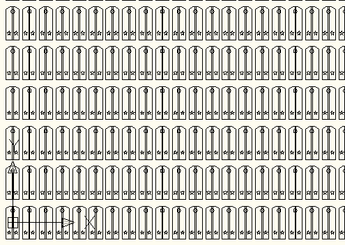
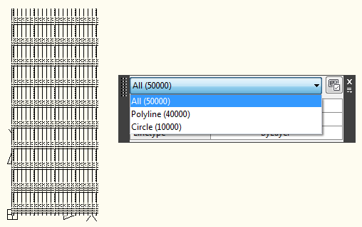
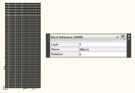
When a drawing contains a large number of objects of the same type, using blocks greatly reduces the size of the drawing file. The following code will help us to feel this:
The code is very simple: there are two procedures -
This is followed by two commands - HabrCommand_DrawFigures and HabrCommand_DrawBlocks . The first draws 10,000 sets of shapes in the drawing, the second draws 10,000 entries of the block.
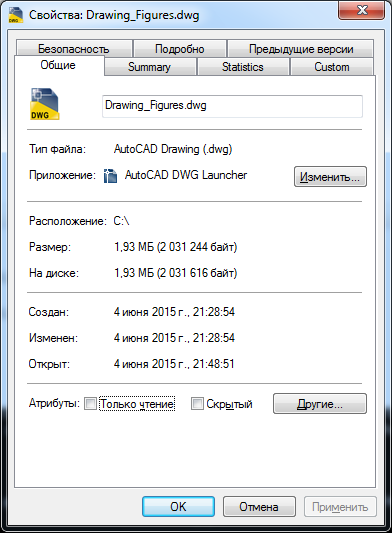
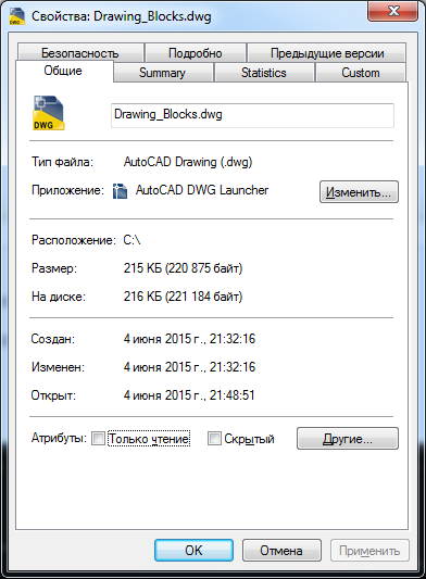
Run AutoCAD, execute the first command, save the drawing. Then close AutoCAD and repeat the same procedure for the second command. As a result, we get two dwg-file. Let's compare their sizes.
Some increase in the size of the drawing file is not good, but not so terrible: Russia is big, there is enough space for everyone. However, there are problems and more serious.
Imagine that in the aforementioned Order №1500 made an addition, strictly regulating the location of the buttons on the chase, and we need to move on all shoulder straps a circle slightly higher from the current position.
If we used blocks, the problem is solved in several lines of code: we simply open the definition of the block, find a circle there and shift its center to the desired point. Since all occurrences of the block refer to the same definition, after the execution of the command, they will all be updated automatically.
A small detail: AutoCAD does update all the occurrences of the blocks, but to see it, you need to run the REGEN command :
Of course, a similar operation can be rotated in the case of geometric shapes, not block occurrences, but then you have to work with the whole drawing and change the coordinates of the center of the circle not once, but ten thousand. I did not conduct tests, but I think that this procedure will take a little longer than editing the block definition.
On the other hand, each coin has obverse and reverse, and the use of blocks imposes its own limitations.
For example, if it is necessary to replace the lieutenant shoulder strap, located in the eleventh row and forty-second column, with a captain, then using blocks in no normal way, we cannot do it.
It is necessary either to create a new block for the captain, or to finish drawing asterisks manually, or to resort to some additional distortions.
A brief conclusion (where would it be without it): the use of blocks can save a lot of time and effort, but they must be applied reasonably, if necessary.
On this I, perhaps, complete. Next time I will tell about the search and editing of objects in the drawing. As always, I will be glad to any comments, comments and suggestions - in the comments or drugs.
Thanks for attention!
public static string disclaimer = " AutoCAD. – ." Introduction
If, when working with a drawing, it becomes necessary to create objects of the same type, then it is best to do this using the mechanism of blocks — named groups of objects that behave as a single object. General information about the blocks can be found here .
It is important to be able to clearly distinguish between two concepts: the definition of a block and the occurrence of a block . A detailed description of the differences is given here (English) and here (rus). Briefly set out the essence: when we create a new block, AutoCAD places its description in a special block table. This description is called a block definition . The block definition exists exclusively in the block table and is not displayed in the drawing. Directly on the drawing field, AutoCAD places a block reference entry — a link to the block definition. When the block definition is changed, all occurrences of the block repeat these changes. Further in the article I will sometimes omit the first word (“definition” or “entry”) and write simply “block”.
')
Nb:
I must say that I personally like the translation of a “block copy” much more than the “block entry”. But since it is so written in the documentation ...
As they say, honor your father, honor your mother, and honor the operating manual.
As they say, honor your father, honor your mother, and honor the operating manual.
In the process of communicating with Autocad, I came across two types of blocks: normal and dynamic . The main feature of the second is the ability to set their elements with some “customizable” parameters (for example, the length of a line in a block or its angle of inclination). The main disadvantage of dynamic blocks is that they cannot be created using the .NET API.
I will tell about dynamic blocks another time. In the meantime, let's see how you can work with ordinary blocks.
Creating a block manually using AutoCAD
To begin, let's create a block directly in AutoCAD. There will be no programming here - but the ability to create a block manually is useful in order to be able to at least approximately estimate the result of the plug-in. Details of the process - under the spoiler.
If the reader is already familiar with editing blocks in AutoCAD, then he will not learn anything new from this section.
So, firstly, you need to add elements to the drawing, which we will combine into a block. To begin with, add a simple circle to the block.
In the AutoCAD command line, execute the CIRCLE command, then specify the center and radius. A circle will appear on the drawing:

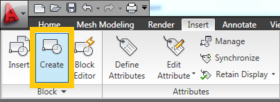
Select the circle and execute the BLOCK command. A block creation menu will appear on the screen. Pressing the “Create” button on the “Block” panel will lead to a similar result:
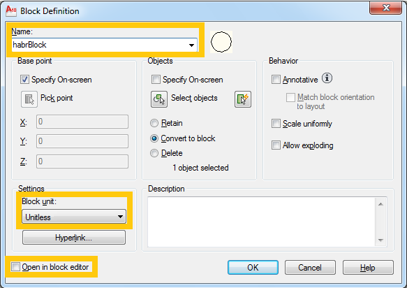
Set the name of the block, set the unit of measure “Unitless” and uncheck the box “Open in Block Editor”, then click “OK”:
After that, AutoCAD will ask you to specify a point on the drawing, which will be the base for the block. Usually, the center of the block or its lower left corner is set as this point. We indicate the center point of the circle as the base point.
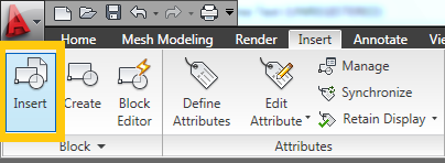
We have completed the creation of the block. The first block entry will be added to the drawing automatically and will replace the elements from which this block was created. To add several occurrences of a created block to a drawing, you can use the INSERT command or the button of the same name in the “Block” panel:
After executing the command or pressing the button, the block insertion window will appear on the screen:
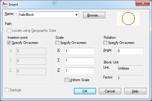
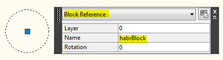
Select the desired block in the list, click "OK", specify the insertion point - and the block appears in the drawing. You can make sure that this is a block by selecting the object and looking at the properties window:
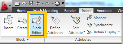
To edit blocks, use the editor, which is called by the BEDIT command or the corresponding button on the “Block” panel:
After executing a command or pressing the mentioned button, a window for selecting a block definition will appear on the screen:

In this window, you must select a definition that we will edit, and click "OK". After that, AutoCAD will open the block editor. Let's go over the most important, in my opinion, important editor panel buttons:

Inside the editor, you can add new objects to the block definition and delete unnecessary ones. Editing a block is similar to editing a regular drawing.
This completes the brief excursion into the creation of blocks in AutoCAD. You can go to the code. :-)
In the AutoCAD command line, execute the CIRCLE command, then specify the center and radius. A circle will appear on the drawing:
Select the circle and execute the BLOCK command. A block creation menu will appear on the screen. Pressing the “Create” button on the “Block” panel will lead to a similar result:
Set the name of the block, set the unit of measure “Unitless” and uncheck the box “Open in Block Editor”, then click “OK”:
Nb:
The choice of units of measurement allows you to set the block size, which will be automatically recalculated in different measurement systems (European, with meters and millimeters - and American, with feet and inches). If you set the value to "Unitless", the block will use the units that are installed in the drawing. I have always set the value “Unitless”; good or bad - I do not know.
After that, AutoCAD will ask you to specify a point on the drawing, which will be the base for the block. Usually, the center of the block or its lower left corner is set as this point. We indicate the center point of the circle as the base point.
We have completed the creation of the block. The first block entry will be added to the drawing automatically and will replace the elements from which this block was created. To add several occurrences of a created block to a drawing, you can use the INSERT command or the button of the same name in the “Block” panel:
After executing the command or pressing the button, the block insertion window will appear on the screen:
Select the desired block in the list, click "OK", specify the insertion point - and the block appears in the drawing. You can make sure that this is a block by selecting the object and looking at the properties window:
To edit blocks, use the editor, which is called by the BEDIT command or the corresponding button on the “Block” panel:
After executing a command or pressing the mentioned button, a window for selecting a block definition will appear on the screen:
In this window, you must select a definition that we will edit, and click "OK". After that, AutoCAD will open the block editor. Let's go over the most important, in my opinion, important editor panel buttons:
- Save Block - save all changes made. After closing the block editor, all block occurrences placed on the drawing will be updated according to the changes in the block definition.
- Authoring Palettes - show or hide the attribute window. This window is useful when working with dynamic blocks.
- Point - in this pop-up submenu there is a “Basepoint” item, with which you can set a new base point for a block.
- Close Block Editor - close the block editor. All unsaved changes will be lost.
Inside the editor, you can add new objects to the block definition and delete unnecessary ones. Editing a block is similar to editing a regular drawing.
This completes the brief excursion into the creation of blocks in AutoCAD. You can go to the code. :-)
Block creation using the AutoCAD .NET API
An example of creating a simple block
This section is based on the corresponding post on the Kean Walmsley blog (our example compared to the original source will be much easier). We will create the simplest block consisting of a polyline, a circle and a block of text.
a little about sausage cuts
By the way, since I started talking about sausage trimmings ...
Over the past couple of years (God, how time flies!) A lot of good things have happened. In particular, the Best and Greatest Company In The World still released a free professional version of Visual Studio.
Yes, Visual Studio Community Edition takes up more space than Express, and its interface is a bit more complicated - but sooner or later the developer usually needs to work with IDE add-ons, and they are not supported in Express versions. So it goes.
A real-life example: the author of these lines had fun writing a plugin in VS Express, and nothing foreshadowed trouble ... until the task to add an installer came up (a msi file created using Wix technology). As a result, all the installer code had to be written in Notepad ++, every minute referring to the documentation, and compiled manually.
And in Visual Studio Professional you could just plug in a plug-in for working with Wix and do everything directly in the IDE - with hints, code completion and compilation right in the project. Can. Would…
In general, if you work in a company that has no more than 250 PCs and an annual income of less than $ 1,000,000, I highly recommend that if you have a couple of extra, meaningless hours of life, you can spend it on installing this product and continue to work with it.
If there are no meaningless hours in your life, then realize that everything is perishable, life is pain, and dragging out your existence without the established Visual Studio Community Edition only means increasing the entropy of this world.
To create a block and place its entry on a drawing, you must do the following:
- Create a new entry in the block table (block definition).
- Add the necessary geometric objects to the block definition.
- Add a block entry to the drawing.
So let's get started.
I will no longer dwell on such minor features of creating a plug-in as connecting external links, banning
CopyLocal , specifying the version of .NET, and the like — this has been discussed many times in past posts of the cycle. In this example, we will need references to AcMgd and AcDBMgd libraries . There will be little code; Immediately bring it all, and then analyze the details.Code:
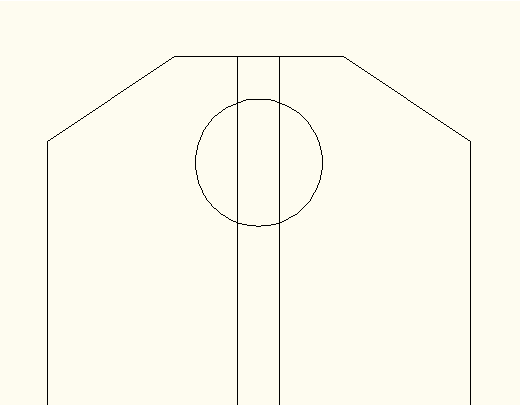
using System; using System.IO; using Autodesk.AutoCAD.Runtime; using Autodesk.AutoCAD.DatabaseServices; using Autodesk.AutoCAD.Geometry; using Autodesk.AutoCAD.ApplicationServices; using Autodesk.AutoCAD.EditorInput; using acad = Autodesk.AutoCAD.ApplicationServices.Application; namespace HabrPlug_SimpleBlock { public class ClassMyAutoCADDLL_SimpleBlock { public class Commands : IExtensionApplication { // AutoCAD "HabrCommand" [CommandMethod("HabrCommand")] public void HabrCommand() { // Document doc = Application.DocumentManager.MdiActiveDocument; Database db = doc.Database; // "Editor" AutoCAD Editor ed = doc.Editor; // const string blockName = "pvtBlock"; // Transaction tr = db.TransactionManager.StartTransaction(); using (tr) { //*** // 1 - //*** // BlockTable bt = (BlockTable)tr.GetObject(db.BlockTableId, OpenMode.ForWrite); // , // - if (bt.Has(blockName)) { ed.WriteMessage("\nA block with the name \"" + blockName + "\" already exists."); return; } // , BlockTableRecord btr = new BlockTableRecord(); btr.Name = blockName; // , // ID ( ) ObjectId btrId = bt.Add(btr); tr.AddNewlyCreatedDBObject(btr, true); //*** // 2 - //*** // Polyline poly = new Polyline(); poly.SetDatabaseDefaults(); poly.AddVertexAt(0, new Point2d(-50, -125), 0, 0, 0); poly.AddVertexAt(1, new Point2d(-50, 105), 0, 0, 0); poly.AddVertexAt(2, new Point2d(-20, 125), 0, 0, 0); poly.AddVertexAt(3, new Point2d(20, 125), 0, 0, 0); poly.AddVertexAt(4, new Point2d(50, 105), 0, 0, 0); poly.AddVertexAt(5, new Point2d(50, -125), 0, 0, 0); poly.AddVertexAt(6, new Point2d(-50, -125), 0, 0, 0); // btr.AppendEntity(poly); tr.AddNewlyCreatedDBObject(poly, true); // Circle cir = new Circle(); cir.SetDatabaseDefaults(); cir.Center = new Point3d(0, 90, 0); cir.Radius = 15; // btr.AppendEntity(cir); tr.AddNewlyCreatedDBObject(cir, true); // DBText text = new DBText(); text.Position = new Point3d(-25, -95, 0); text.Height = 35; text.TextString = "BC"; // btr.AppendEntity(text); tr.AddNewlyCreatedDBObject(text, true); //*** // 3 - //*** // BlockTableRecord ms = (BlockTableRecord)tr.GetObject(bt[BlockTableRecord.ModelSpace], OpenMode.ForWrite); // , ID BlockReference br = new BlockReference(Point3d.Origin, btrId); // ms.AppendEntity(br); tr.AddNewlyCreatedDBObject(br, true); // tr.Commit(); } } // Initialize() Terminate() , IExtensionApplication public void Initialize() { } public void Terminate() { } } } } After loading the plugin and executing the HabrCommand command, we get the following image: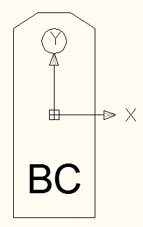
Now let's understand what happens in the code.
First, we carry out preparatory operations: we obtain references to the document, its database and the
Editor property, set the name of the new block, and begin the transaction. There is nothing new in this, except perhaps Editor properties.I could not find detailed information on the
Editor class. I would be glad if someone from more knowledgeable people prompts a link to the imputed description of this class and its methods (or at least where to find it in the ObjectARX Reference). In this example, the Editor class is used only to display a message that a block with the same name already exists in the database. In AutoCAD, this message looks like this:Inside the transaction, we act on the algorithm outlined at the beginning of this subsection.
In the first step, we create a new entry in the block table, for which:
- open the block table (request write access, since we will make changes);
- check if there is a block with the same name in the table (when trying to create a block with a name that is already in the block table, we will get the exception
eDuplicateRecordName, which we absolutely do not need); - create a new block definition;
- set the created block definition name;
- Add the created block definition to the block table and to the transaction.
In the second step, we add the necessary geometric primitives to the created record. We will have three of them: a polyline, a circle and a text.
Adding a polyline and a circle to a drawing was explained in the previous article; with the text everything happens in a similar way. Adding a graphic object to a block usually takes place in three steps:
- the required object is created;
- properties of this object are set;
- The created object is added to the block definition and to the transaction.
This applies to both the polyline and the circle, and to the text. What part of the code is responsible for which item is quite obvious. You can read more about adding text to a drawing here (English) and here (rus).
In the third step, we add the occurrence of the created block to the drawing. The procedure here is:
- opens the model space for recording;
- a new block entry is created;
- the created block entry is added to the model space and to the transaction.
Let us dwell a little bit more on the constructor of the
BlockReference class used to create a new block entry. This constructor takes two parameters: the block placement point (the base entry point of the block will be combined with this point) and the block definition ID. In other words, we need to tell AutoCAD which block we want to see and where . In our example, the origin of the block is the origin ( Point3d.Origin ), and we saved the block definition ID in the first step when creating this definition.Using blocks already present in the document block table
If in the previous example execute the HabrCommand command, then remove the appeared block from the drawing and execute the HabrCommand again, we will see the message “A block with the name„ pvtBlock “already exists”, and nothing will appear on the drawing. To use a previously created block definition, you need to know the
ObjectID this definition. In our case, the code can be rewritten as:Command Code:
[CommandMethod("HabrCommand")] public void HabrCommand() { // Document doc = Application.DocumentManager.MdiActiveDocument; Database db = doc.Database; // "Editor" AutoCAD Editor ed = doc.Editor; // const string blockName = "pvtBlock"; // Transaction tr = db.TransactionManager.StartTransaction(); using (tr) { //*** // 1 - ( ID ) //*** // BlockTable bt = (BlockTable)tr.GetObject(db.BlockTableId, OpenMode.ForRead); // , // - ID ObjectId btrId; if (bt.Has(blockName)) { btrId = bt[blockName]; } else { // bt.UpgradeOpen(); // , BlockTableRecord btr = new BlockTableRecord(); btr.Name = blockName; // , ID btrId = bt.Add(btr); // tr.AddNewlyCreatedDBObject(btr, true); //*** // 2 - //*** // Polyline poly = new Polyline(); poly.SetDatabaseDefaults(); poly.AddVertexAt(0, new Point2d(-50, -125), 0, 0, 0); poly.AddVertexAt(1, new Point2d(-50, 105), 0, 0, 0); poly.AddVertexAt(2, new Point2d(-20, 125), 0, 0, 0); poly.AddVertexAt(3, new Point2d(20, 125), 0, 0, 0); poly.AddVertexAt(4, new Point2d(50, 105), 0, 0, 0); poly.AddVertexAt(5, new Point2d(50, -125), 0, 0, 0); poly.AddVertexAt(6, new Point2d(-50, -125), 0, 0, 0); // btr.AppendEntity(poly); tr.AddNewlyCreatedDBObject(poly, true); // Circle cir = new Circle(); cir.SetDatabaseDefaults(); cir.Center = new Point3d(0, 90, 0); cir.Radius = 15; // btr.AppendEntity(cir); tr.AddNewlyCreatedDBObject(cir, true); // DBText text = new DBText(); text.Position = new Point3d(-33, -95, 0); text.Height = 35; text.TextString = "BC"; // btr.AppendEntity(text); tr.AddNewlyCreatedDBObject(text, true); } //*** // 3 - //*** // BlockTableRecord ms = (BlockTableRecord)tr.GetObject(bt[BlockTableRecord.ModelSpace], OpenMode.ForWrite); // , ID BlockReference br = new BlockReference(Point3d.Origin, btrId); // ms.AppendEntity(br); tr.AddNewlyCreatedDBObject(br, true); // tr.Commit(); } } If we now execute the HabrCommand command, then remove the block that appears from the drawing and rerun the HabrCommand command, the occurrence of our block will reappear on the drawing. In this case, a new block definition will not be created - the plugin will take the record that already exists in the block table.
In the
UpgradeOpen() example, I used the UpgradeOpen() method for a UpgradeOpen() , which quite often appears in the examples and documentation. Let's see how it works.If in the first example we immediately opened the block table for writing (
OpenMode.ForWrite ), now we first open it only for reading ( OpenMode.ForRead ). This is enough for us to view the table and find out whether it contains a block with our name. If there is such a block, then we can read its ObjectID , for which, again, we only have access for reading. If there is no block with our name in the table, then we need to add it, and for this we need write access. To get this access, the UpgradeOpen() method is used - after calling this method we can work with the block table, as if we opened it with the OpenMode.ForWrite access OpenMode.ForWrite .Nb:
Using
UpgradeOpen() is probably good practice. At least Kean Walmsley does exactly that. But I don’t have detailed information about what treasures and life benefits come to those who use UpgradeOpen() . I myself did not use this construction in my work and did not feel any particular disappointment about this. If someone can submit their position on the use of UpgradeOpen() - I will be glad to see it in the comments or drugs.Changing the position of the block insert
Where the block will appear in the drawing, it
- from the base point specified in the block definition;
- from the insertion point specified in the block entry.
In our example, the base point is located in the center of the block.
Picture: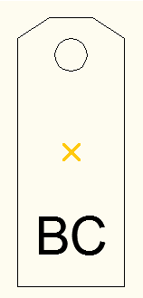
Note that when creating a block definition, we never set the base point anywhere explicitly - in such a case, AutoCAD assumes that the base point is the origin. In our example, the "center" of the shape was specially selected so that it coincided with the center of coordinates.
You can manually change the base definition point of a block using the block editor (as described in the first section of the post) or using the .NET API. In the latter case, the
Originclass property is used for this purpose BlockTableRecord. As an example, let's move the base definition point of a block to the bottom left corner. To do this, after specifying the block name, set the property Origin: // btr.Name = blockName; // btr.Origin = new Point3d(-50, -125, 0); The numbers -50 and -125 are the minimum coordinates of our block along the X and Y axes, respectively (such coordinates are the lower left vertex of the polyline, which forms the outer boundary of our block).
Result: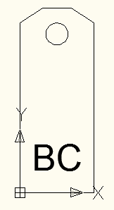
.
.
Now let's deal with the insertion point of the block. It is set for each block entry and shows where its base point will be after inserting the block. This property is set in the class constructor
BlockReference- for example, like this: BlockReference br = new BlockReference(new Point3d(150, 150, 0), btrId); After a simultaneous change of the base point and the insertion point, we get the following picture:
.
.
The block insertion point can also be changed using the
Positionclass property BlockReference: BlockReference br = new BlockReference(Point3d.Origin, btrId); br.Position = new Point3d(150, 150, 0); The effect will be the same as when defining a point directly in the class constructor
BlockReference.Using blocks inside a block
We all love blocks here, so let's add a couple of blocks to our block to simplify the drawing, while we simplify the drawing.
Yo dawg!
Adding a block to a block definition is easy. The main feature is that if we add not a geometric primitive to the block, but an entry of an auxiliary block, then we definitely need to ensure that the definition of this auxiliary block is in the table of document blocks.
Command Code:
[CommandMethod("HabrCommand")] public void HabrCommand() { // Document doc = Application.DocumentManager.MdiActiveDocument; Database db = doc.Database; // "Editor" AutoCAD Editor ed = doc.Editor; // const string blockName = "ltBlock"; // const string auxBlockName = "starBlock"; // Transaction tr = db.TransactionManager.StartTransaction(); using (tr) { // BlockTable bt = (BlockTable)tr.GetObject(db.BlockTableId, OpenMode.ForWrite); //*** // 0 - ( ID ) //*** // , // - ID ObjectId btrIdAux; if (bt.Has(auxBlockName)) { btrIdAux = bt[auxBlockName]; } else { // , BlockTableRecord btr = new BlockTableRecord(); btr.Name = auxBlockName; // , ID btrIdAux = bt.Add(btr); // tr.AddNewlyCreatedDBObject(btr, true); // Polyline poly = new Polyline(); poly.SetDatabaseDefaults(); poly.AddVertexAt(0, new Point2d(0, -6), 0, 0, 0); poly.AddVertexAt(1, new Point2d(-9, -12), 0, 0, 0); poly.AddVertexAt(2, new Point2d(-7, -2), 0, 0, 0); poly.AddVertexAt(3, new Point2d(-14, 6), 0, 0, 0); poly.AddVertexAt(4, new Point2d(-5, 6), 0, 0, 0); poly.AddVertexAt(5, new Point2d(0, 15), 0, 0, 0); poly.AddVertexAt(6, new Point2d(5, 6), 0, 0, 0); poly.AddVertexAt(7, new Point2d(14, 6), 0, 0, 0); poly.AddVertexAt(8, new Point2d(7, -2), 0, 0, 0); poly.AddVertexAt(9, new Point2d(9, -12), 0, 0, 0); poly.AddVertexAt(10, new Point2d(0, -6), 0, 0, 0); // btr.AppendEntity(poly); tr.AddNewlyCreatedDBObject(poly, true); } //*** // ( ID ) //*** //*** // 1 - ( ID ) //*** // , // - ID ObjectId btrId; if (bt.Has(blockName)) { btrId = bt[blockName]; } else { // , BlockTableRecord btr = new BlockTableRecord(); btr.Name = blockName; // , ID btrId = bt.Add(btr); // tr.AddNewlyCreatedDBObject(btr, true); //*** // 2 - //*** // Polyline polyExt = new Polyline(); polyExt.SetDatabaseDefaults(); polyExt.AddVertexAt(0, new Point2d(-50, -125), 0, 0, 0); polyExt.AddVertexAt(1, new Point2d(-50, 105), 0, 0, 0); polyExt.AddVertexAt(2, new Point2d(-20, 125), 0, 0, 0); polyExt.AddVertexAt(3, new Point2d(20, 125), 0, 0, 0); polyExt.AddVertexAt(4, new Point2d(50, 105), 0, 0, 0); polyExt.AddVertexAt(5, new Point2d(50, -125), 0, 0, 0); polyExt.AddVertexAt(6, new Point2d(-50, -125), 0, 0, 0); // btr.AppendEntity(polyExt); tr.AddNewlyCreatedDBObject(polyExt, true); // Polyline polyIn = new Polyline(); polyIn.SetDatabaseDefaults(); polyIn.AddVertexAt(0, new Point2d(-5, -125), 0, 0, 0); polyIn.AddVertexAt(1, new Point2d(-5, 125), 0, 0, 0); polyIn.AddVertexAt(2, new Point2d(5, 125), 0, 0, 0); polyIn.AddVertexAt(3, new Point2d(5, -125), 0, 0, 0); // btr.AppendEntity(polyIn); tr.AddNewlyCreatedDBObject(polyIn, true); // Circle cir = new Circle(); cir.SetDatabaseDefaults(); cir.Center = new Point3d(0, 90, 0); cir.Radius = 15; // btr.AppendEntity(cir); tr.AddNewlyCreatedDBObject(cir, true); // BlockReference starLeft = new BlockReference(new Point3d(-27, -75, 0), btrIdAux); btr.AppendEntity(starLeft); tr.AddNewlyCreatedDBObject(starLeft, true); BlockReference starRight = new BlockReference(new Point3d(27, -75, 0), btrIdAux); btr.AppendEntity(starRight); tr.AddNewlyCreatedDBObject(starRight, true); } //*** // 3 - //*** // BlockTableRecord ms = (BlockTableRecord)tr.GetObject(bt[BlockTableRecord.ModelSpace], OpenMode.ForWrite); // , ID BlockReference br = new BlockReference(new Point3d(150, 150, 0), btrId); // ms.AppendEntity(br); tr.AddNewlyCreatedDBObject(br, true); // tr.Commit(); } } Result: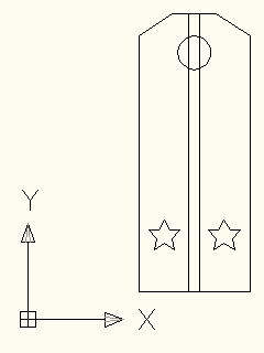
By and large, there is nothing to comment here: we simply add a definition of an auxiliary block to the block table, and then create an entry for the auxiliary block and give it the coordinates of the insertion point.
As a simple independent exercise, readers are invited to paint the elements of the block and bring their size and location in accordance with the Order number 1500 .
Sample: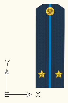
Why use blocks?
There are two main reasons ... Let's start with the second.
The second reason
When a drawing contains a large number of objects of the same type, using blocks greatly reduces the size of the drawing file. The following code will help us to feel this:
Plugin code:
using System; using System.IO; using Autodesk.AutoCAD.Runtime; using Autodesk.AutoCAD.DatabaseServices; using Autodesk.AutoCAD.Geometry; using Autodesk.AutoCAD.ApplicationServices; using Autodesk.AutoCAD.EditorInput; using acad = Autodesk.AutoCAD.ApplicationServices.Application; namespace HabrPlug_SimpleBlock { public class ClassMyAutoCADDLL_SimpleBlock { public class Commands : IExtensionApplication { // , public void drawFigure(double x, double y) { // Document doc = Application.DocumentManager.MdiActiveDocument; Database db = doc.Database; // Transaction tr = db.TransactionManager.StartTransaction(); using (tr) { // BlockTable bt = (BlockTable)tr.GetObject(db.BlockTableId, OpenMode.ForWrite); // BlockTableRecord ms = (BlockTableRecord)tr.GetObject(bt[BlockTableRecord.ModelSpace], OpenMode.ForWrite); // Polyline polyExt = new Polyline(); polyExt.SetDatabaseDefaults(); polyExt.AddVertexAt(0, new Point2d(x - 50, y - 125), 0, 0, 0); polyExt.AddVertexAt(1, new Point2d(x - 50, y + 105), 0, 0, 0); polyExt.AddVertexAt(2, new Point2d(x - 20, y + 125), 0, 0, 0); polyExt.AddVertexAt(3, new Point2d(x + 20, y + 125), 0, 0, 0); polyExt.AddVertexAt(4, new Point2d(x + 50, y + 105), 0, 0, 0); polyExt.AddVertexAt(5, new Point2d(x + 50, y - 125), 0, 0, 0); polyExt.AddVertexAt(6, new Point2d(x - 50, y - 125), 0, 0, 0); // ms.AppendEntity(polyExt); tr.AddNewlyCreatedDBObject(polyExt, true); // Polyline polyIn = new Polyline(); polyIn.SetDatabaseDefaults(); polyIn.AddVertexAt(0, new Point2d(x - 5, y - 125), 0, 0, 0); polyIn.AddVertexAt(1, new Point2d(x - 5, y + 125), 0, 0, 0); polyIn.AddVertexAt(2, new Point2d(x + 5, y + 125), 0, 0, 0); polyIn.AddVertexAt(3, new Point2d(x + 5, y - 125), 0, 0, 0); // ms.AppendEntity(polyIn); tr.AddNewlyCreatedDBObject(polyIn, true); // Circle cir = new Circle(); cir.SetDatabaseDefaults(); cir.Center = new Point3d(x, y + 90, 0); cir.Radius = 15; // ms.AppendEntity(cir); tr.AddNewlyCreatedDBObject(cir, true); // , Polyline starLeft= new Polyline(); starLeft.SetDatabaseDefaults(); starLeft.AddVertexAt(0, new Point2d(x - 27, y - 75 - 6), 0, 0, 0); starLeft.AddVertexAt(1, new Point2d(x - 27 - 9, y - 75 - 12), 0, 0, 0); starLeft.AddVertexAt(2, new Point2d(x - 27 - 7, y - 75 - 2), 0, 0, 0); starLeft.AddVertexAt(3, new Point2d(x - 27 - 14, y - 75 + 6), 0, 0, 0); starLeft.AddVertexAt(4, new Point2d(x - 27 - 5, y - 75 + 6), 0, 0, 0); starLeft.AddVertexAt(5, new Point2d(x - 27, y - 75 + 15), 0, 0, 0); starLeft.AddVertexAt(6, new Point2d(x - 27 + 5, y - 75 + 6), 0, 0, 0); starLeft.AddVertexAt(7, new Point2d(x - 27 + 14, y - 75 + 6), 0, 0, 0); starLeft.AddVertexAt(8, new Point2d(x - 27 + 7, y - 75 - 2), 0, 0, 0); starLeft.AddVertexAt(9, new Point2d(x - 27 + 9, y - 75 - 12), 0, 0, 0); starLeft.AddVertexAt(10, new Point2d(x - 27, y - 75 - 6), 0, 0, 0); ms.AppendEntity(starLeft); tr.AddNewlyCreatedDBObject(starLeft, true); Polyline starRight = new Polyline(); starRight.SetDatabaseDefaults(); starRight.AddVertexAt(0, new Point2d(x + 27, y - 75 - 6), 0, 0, 0); starRight.AddVertexAt(1, new Point2d(x + 27 - 9, y - 75 - 12), 0, 0, 0); starRight.AddVertexAt(2, new Point2d(x + 27 - 7, y - 75 - 2), 0, 0, 0); starRight.AddVertexAt(3, new Point2d(x + 27 - 14, y - 75 + 6), 0, 0, 0); starRight.AddVertexAt(4, new Point2d(x + 27 - 5, y - 75 + 6), 0, 0, 0); starRight.AddVertexAt(5, new Point2d(x + 27, y - 75 + 15), 0, 0, 0); starRight.AddVertexAt(6, new Point2d(x + 27 + 5, y - 75 + 6), 0, 0, 0); starRight.AddVertexAt(7, new Point2d(x + 27 + 14, y - 75 + 6), 0, 0, 0); starRight.AddVertexAt(8, new Point2d(x + 27 + 7, y - 75 - 2), 0, 0, 0); starRight.AddVertexAt(9, new Point2d(x + 27 + 9, y - 75 - 12), 0, 0, 0); starRight.AddVertexAt(10, new Point2d(x + 27, y - 75 - 6), 0, 0, 0); ms.AppendEntity(starRight); tr.AddNewlyCreatedDBObject(starRight, true); // tr.Commit(); } } // , public void drawBlock(double x, double y) { // Document doc = Application.DocumentManager.MdiActiveDocument; Database db = doc.Database; // "Editor" AutoCAD Editor ed = doc.Editor; // const string blockName = "ltBlock"; const string auxBlockName = "starBlock"; // Transaction tr = db.TransactionManager.StartTransaction(); using (tr) { // BlockTable bt = (BlockTable)tr.GetObject(db.BlockTableId, OpenMode.ForWrite); //*** // 0 - ( ID ) //*** ObjectId btrIdAux; if (bt.Has(auxBlockName)) { btrIdAux = bt[auxBlockName]; } else { // , BlockTableRecord btr = new BlockTableRecord(); btr.Name = auxBlockName; // , ID btrIdAux = bt.Add(btr); // tr.AddNewlyCreatedDBObject(btr, true); // Polyline poly = new Polyline(); poly.SetDatabaseDefaults(); poly.AddVertexAt(0, new Point2d(0, -6), 0, 0, 0); poly.AddVertexAt(1, new Point2d(-9, -12), 0, 0, 0); poly.AddVertexAt(2, new Point2d(-7, -2), 0, 0, 0); poly.AddVertexAt(3, new Point2d(-14, 6), 0, 0, 0); poly.AddVertexAt(4, new Point2d(-5, 6), 0, 0, 0); poly.AddVertexAt(5, new Point2d(0, 15), 0, 0, 0); poly.AddVertexAt(6, new Point2d(5, 6), 0, 0, 0); poly.AddVertexAt(7, new Point2d(14, 6), 0, 0, 0); poly.AddVertexAt(8, new Point2d(7, -2), 0, 0, 0); poly.AddVertexAt(9, new Point2d(9, -12), 0, 0, 0); poly.AddVertexAt(10, new Point2d(0, -6), 0, 0, 0); // btr.AppendEntity(poly); tr.AddNewlyCreatedDBObject(poly, true); } //*** // 1 - ( ID ) //*** // , // - ID ObjectId btrId; if (bt.Has(blockName)) { btrId = bt[blockName]; } else { // , BlockTableRecord btr = new BlockTableRecord(); btr.Name = blockName; // , ID btrId = bt.Add(btr); // tr.AddNewlyCreatedDBObject(btr, true); //*** // 2 - //*** // Polyline polyExt = new Polyline(); polyExt.SetDatabaseDefaults(); polyExt.AddVertexAt(0, new Point2d(-50, -125), 0, 0, 0); polyExt.AddVertexAt(1, new Point2d(-50, 105), 0, 0, 0); polyExt.AddVertexAt(2, new Point2d(-20, 125), 0, 0, 0); polyExt.AddVertexAt(3, new Point2d(20, 125), 0, 0, 0); polyExt.AddVertexAt(4, new Point2d(50, 105), 0, 0, 0); polyExt.AddVertexAt(5, new Point2d(50, -125), 0, 0, 0); polyExt.AddVertexAt(6, new Point2d(-50, -125), 0, 0, 0); // btr.AppendEntity(polyExt); tr.AddNewlyCreatedDBObject(polyExt, true); // Polyline polyIn = new Polyline(); polyIn.SetDatabaseDefaults(); polyIn.AddVertexAt(0, new Point2d(-5, -125), 0, 0, 0); polyIn.AddVertexAt(1, new Point2d(-5, 125), 0, 0, 0); polyIn.AddVertexAt(2, new Point2d(5, 125), 0, 0, 0); polyIn.AddVertexAt(3, new Point2d(5, -125), 0, 0, 0); // btr.AppendEntity(polyIn); tr.AddNewlyCreatedDBObject(polyIn, true); // Circle cir = new Circle(); cir.SetDatabaseDefaults(); cir.Center = new Point3d(0, 90, 0); cir.Radius = 15; // btr.AppendEntity(cir); tr.AddNewlyCreatedDBObject(cir, true); // BlockReference starLeft = new BlockReference(new Point3d(-27, -75, 0), btrIdAux); btr.AppendEntity(starLeft); tr.AddNewlyCreatedDBObject(starLeft, true); BlockReference starRight = new BlockReference(new Point3d(27, -75, 0), btrIdAux); btr.AppendEntity(starRight); tr.AddNewlyCreatedDBObject(starRight, true); } //*** // 3 - //*** // BlockTableRecord ms = (BlockTableRecord)tr.GetObject(bt[BlockTableRecord.ModelSpace], OpenMode.ForWrite); // , ID BlockReference br = new BlockReference(new Point3d(x, y, 0), btrId); // ms.AppendEntity(br); tr.AddNewlyCreatedDBObject(br, true); // tr.Commit(); } } // AutoCAD "HabrCommand_DrawFigures" [CommandMethod("HabrCommand_DrawFigures")] public void HabrCommand_DrawFigures() { for (int x = 0; x < 100; x++) { for (int y = 0; y < 100; y++) { drawFigure(125 * x, 300 * y); } } } // AutoCAD "HabrCommand_DrawBlocks" [CommandMethod("HabrCommand_DrawBlocks")] public void HabrCommand_DrawBlocks() { for (int x = 0; x < 100; x++) { for (int y = 0; y < 100; y++) { drawBlock(125 * x, 300 * y); } } } // Initialize() Terminate() , IExtensionApplication public void Initialize() { } public void Terminate() { } } } } The code is very simple: there are two procedures -
drawFigure(double x, double y)and drawBlock(double x, double y). The first draws a set of shapes at a given point that exactly repeats our block, and the second creates an entry of our block at a given point.This is followed by two commands - HabrCommand_DrawFigures and HabrCommand_DrawBlocks . The first draws 10,000 sets of shapes in the drawing, the second draws 10,000 entries of the block.
Work results
:

:
:
:
:
:
:
:
:
Run AutoCAD, execute the first command, save the drawing. Then close AutoCAD and repeat the same procedure for the second command. As a result, we get two dwg-file. Let's compare their sizes.
The end is a bit predictable:
:
:
:
First reason
Some increase in the size of the drawing file is not good, but not so terrible: Russia is big, there is enough space for everyone. However, there are problems and more serious.
Imagine that in the aforementioned Order №1500 made an addition, strictly regulating the location of the buttons on the chase, and we need to move on all shoulder straps a circle slightly higher from the current position.
If we used blocks, the problem is solved in several lines of code: we simply open the definition of the block, find a circle there and shift its center to the desired point. Since all occurrences of the block refer to the same definition, after the execution of the command, they will all be updated automatically.
Command Code:
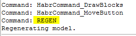
[CommandMethod("HabrCommand_MoveButton")] public void HabrCommand_MoveButton() { // Document doc = Application.DocumentManager.MdiActiveDocument; Database db = doc.Database; // "Editor" AutoCAD Editor ed = doc.Editor; // const string blockName = "ltBlock"; // Transaction tr = db.TransactionManager.StartTransaction(); using (tr) { // BlockTable bt = (BlockTable)tr.GetObject(db.BlockTableId, OpenMode.ForWrite); // , // - if (!bt.Has(blockName)) { ed.WriteMessage("Block not found!"); return; } else { // BlockTableRecord btr = tr.GetObject(bt[blockName], OpenMode.ForWrite) as BlockTableRecord; // ID foreach (ObjectId id in btr) { // ID , DBObject obj = tr.GetObject(id, OpenMode.ForRead); // - (Circle), if (obj.GetType() == typeof(Circle)) { obj.UpgradeOpen(); (obj as Circle).Center = new Point3d(0, 100, 0); } } // tr.Commit(); } } A small detail: AutoCAD does update all the occurrences of the blocks, but to see it, you need to run the REGEN command :
Result:
BEFORE:

:
:
Of course, a similar operation can be rotated in the case of geometric shapes, not block occurrences, but then you have to work with the whole drawing and change the coordinates of the center of the circle not once, but ten thousand. I did not conduct tests, but I think that this procedure will take a little longer than editing the block definition.
On the other hand, each coin has obverse and reverse, and the use of blocks imposes its own limitations.
For example, if it is necessary to replace the lieutenant shoulder strap, located in the eleventh row and forty-second column, with a captain, then using blocks in no normal way, we cannot do it.
It is necessary either to create a new block for the captain, or to finish drawing asterisks manually, or to resort to some additional distortions.
A brief conclusion (where would it be without it): the use of blocks can save a lot of time and effort, but they must be applied reasonably, if necessary.
On this I, perhaps, complete. Next time I will tell about the search and editing of objects in the drawing. As always, I will be glad to any comments, comments and suggestions - in the comments or drugs.
Thanks for attention!
Source: https://habr.com/ru/post/259303/
All Articles