The implementation of weather effects. Precipitation
The task of correctly simulating weather effects has been stretching from the very beginning of the gaming industry. The weather is an integral part of our life, which means that games without weather effects are not quite complete. That is why a rare game does without at least a very primitive weather simulation. Since the task is very old, there are many outdated solutions that are still being used, despite the obviously low efficiency. And if the usual fog is simple, then the implementation of precipitation causes some difficulties.
So, what is rain or snow in the real world?
These are billions of small particles that more or less evenly fill the space from the earth itself to the clouds. In case we had unlimited computational resources - all that would have to be done to simulate precipitation - to process this billion particles, evenly distributed over the location. However, our computing power is very limited and even a million particles in real time can be counted only if the location consists of only precipitation, no landscape, objects and everything else. What to say about the billion.
')
In this regard, in the process of implementing precipitation we face three separate tasks:
- Reducing the number of particles from a billion to an acceptable 20-50 thousand.
- Reducing the amount of computation per particle to the minimum.
- Transfer all calculations to the GPU.
To begin, consider how we will achieve this:
We will reduce the number of particles on the basis of a simple conclusion: the observer does not see the entire billion particles. He does not see the particles behind him, too far below and above. This already cuts the number of particles by 3-4 times. But 200 million is a bit too much. Here we come to the aid of a little trick. The fact is that the particles are very small and in reality, at a distance of several meters, they turn into a uniform veil. Therefore, “honestly” we need to draw only particles in front of an observer at a distance of about 10 meters. 50,000 particles in such conditions is enough to create the appearance of very dense snowfall. Also, it is important to understand that in the real world, the particle size is measured in millimeters. In the case of a computer simulation, we can safely increase the particle size to a few centimeters and it will still look good, because the observer has no opportunity to examine the particles and compare their sizes with the objects around.
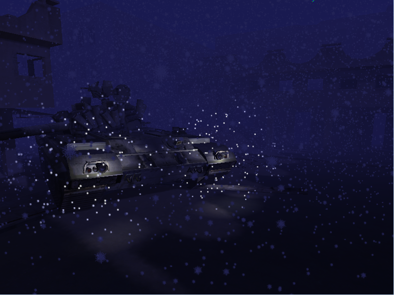
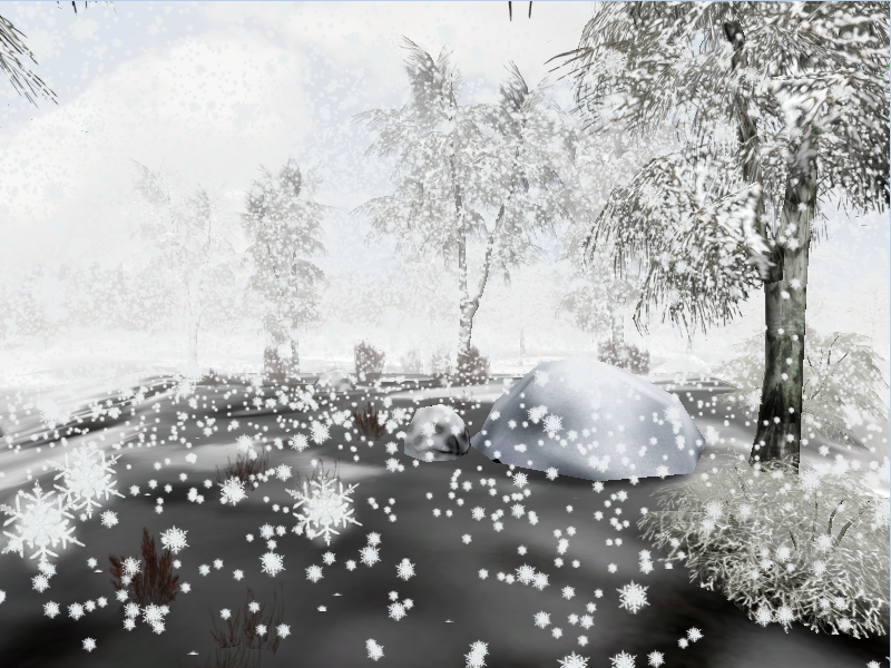
Here is the location with precipitations in the form of snow with the following settings: The number of particles is 25,000 within 15 meters, the particle size is 10 centimeters, at a distance of 20 to 100 meters a white mist with a density of 80%.
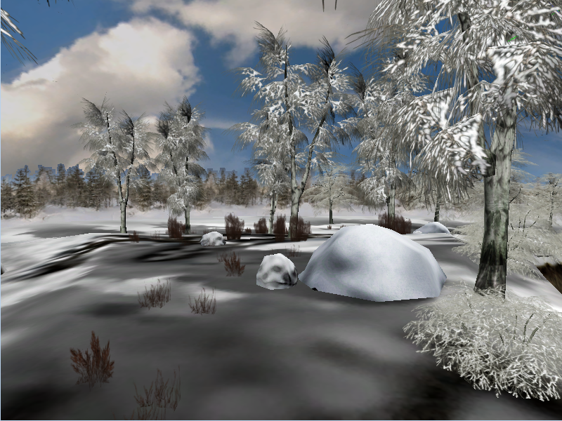
Here is the same location with disabled rainfall:
Despite the fact that the particle size is unnaturally large, the observer perceives this as absolutely normal - he cannot estimate the distance to the particle, and it seems that large particles are large because they are very close. Although in reality it is not.
The second important task is to reduce the calculations for each particle to a minimum. Even 25,000 particles in each frame is a sizeable load. Therefore, even a small optimization matters. So, let us remember: what calculations we need to carry out over a particle, if we consider it honestly:
- Appearance in random xy volume coordinates
- Acceleration due to gravity
- Z air resistance
- Air resistance X, Y (wind)
- Intersection with the geometry (so that the particles do not pass through obstacles, for example, the roof of the house where the observer is located).
These parameters are very important if we are working on an exact simulation. However, in games, the visual component is important for us, not the accuracy of a physical simulation. The observer does not have the ability to trace the behavior of one particular particle, so you can safely get rid of randomness and fair calculation. Even if a particle goes from cycle to cycle the same way without changes - the observer will not notice this, since 24999 particles will move alongside their own paths (even if they are looped).
Therefore:
- Particles always appear in the same coordinates relative to the block. These coordinates are the coordinates transmitted via the vertex buffer.
- Acceleration and resistance in Z, we ignore and believe that they overlap each other. That is, the particle moves at a constant speed.
- Ignore honest calculations and simply add the wind speed * time to the initial XY coordinates of the particle.
- We bake all static geometry in the height map and simply check the Z-position of the particle and the height of the particle in the XY coordinates. If the particle has dropped below the height at this point - we do not draw it.
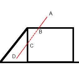
It is worth noting that the simplified intersection with the geometry does not always work, and sometimes it can even create artifacts. Visually, it looks like the appearance of particles from the void.
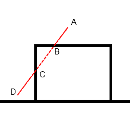
Our particle begins its journey at point “A” located above the house, and as long as it descends to point “B”, everything is fine. It is above geometry. As soon as she crossed the height “B”, she became invisible, because is under the roof. This continues until it passes point “C”. Due to the influence of the wind, the particle moved outside the house and again turned out to be higher than the geometry, as a result of which it again becomes visible. Visually, it looks like the particles "appear" from the wall of the house. This is a rather unpleasant artifact and it is worth bearing in mind that it exists. If we try to “honestly” calculate the intersection of the particle vector with the geometry, we risk very much slowing down the operation of the precipitation system. But there is a fairly simple hint: modify the height map in accordance with the deviation of particles due to wind:
The only disadvantage of this solution is that you will have to rebuild the height map when the wind changes.
Igrostroy has always been a compromise between artifacts and speed, and this case is just one of the examples of such a compromise. The artifact is the more noticeable, the higher the wind speed.
The last stage of optimization is the transfer of calculations to the GPU. Actually, we didn’t have any special calculations after the previous step.
XY coordinates are calculated from the origin coordinates plus the offset added by the wind:
XY = Start.xy + Wind * Time;
The Z coordinate is calculated by subtracting from the initial coordinate of the fall velocity multiplied by the time:
Z = Start.z - Speed * Time
Well, and the last thing - the visibility of a particle is determined by comparing the obtained Z coordinate with the height of the geometry at this point:
IsVisible = MapHeight (XY) <Z
All these three operations are easily transferred to the GPU. There is also a calculation of transparency, taking into account the distance from the observer, the use of lighting, and other trifles. But they are already used on the GPU and, obviously, will not become a problem during the transfer.
Before proceeding to the description of the specific implementation of all of the above, it is worthwhile to dwell on another important aspect of the implementation. Namely, on determining where in the world to draw the block of particles we created and what shape it should be.
The first thing that comes to mind during implementation is part of a cylinder, centered on the coordinates of the observer and sliced along the edges of the frustum.
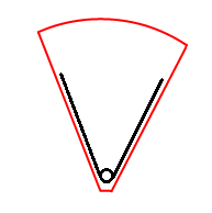
This is a very seductive option, because generating particles only within the resulting piece of the cylinder, we can only work with the zone that the observer sees. That is, almost all 50,000 generated particles will be on the screen! Very economical! But everything breaks down when we give the observer the opportunity to move and rotate the camera. In order for the particles to remain inside the frustum, we will have to move the cylinder along with the observer. That is, regardless of how the observer moves and turns - he always sees the same particles! This is no good. Therefore, we will dwell on another variant, there are quite a lot of degenerate particles in it, but at the same time the rotation and movement of the camera does not break the work of the particle system and when moving and rotating the camera it seems that we see new particles, although in reality this is all the same block particles.
The idea is that we work with a zone in the form of a cube. During initial initialization, particles are randomly placed on the XoY plane in accordance with the dimensions of the cube.
The coordinates of the particles fill a square piece at the origin of the world the size of a block:
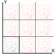
Black dots mark the coordinates of the particles as is. Red - these are the same particles, only offset by the block size. How it works: we have a frustum observer. We take and enter our cube in frustum. The main conditions for inscribing three:
1) The block does not rotate. Entry is carried out only by movement.
2) The coordinates of the observer should be contained in the block.
3) The distance from the observer to the intersection of both faces of the frustum with the sides of the block should be the same as possible.
After fitting the block into the frustum, we get something like this:

Frustum is much bigger than our block, but it doesn't matter, because particles must be only in the first few meters of the observer.
After we have obtained the coordinates of the inscribed block, we assume the XY coordinates for each particle, taking into account the application of the wind. For simplicity, in this example, I will assume that there is no wind and, accordingly, the coordinates of the particles have not changed their XY coordinates.
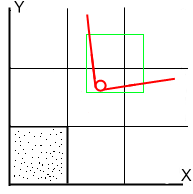
We displace each particle so that it falls into the inscribed block. To do this, we shift the particles along X and Y, but do not shift them smoothly, but in increments equal to the size of the block.
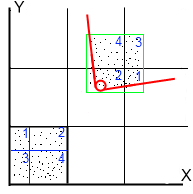
It turns out that the particles do not move each by itself, but in blocks. For example, particles trapped in block “1” will move along X by 2 sizes, and along Y by 1.
Thus, all particles will be inside the zone on their projections in accordance with the displacement on the grid.
Moving, the observer will shift the zone and the particles, respectively, will move to new projections.
For example, if the observer moves from X to the right from the current position, blocks “4” and “2” will decrease, and blocks “3” and “1”, on the contrary, will increase. Particles that have fallen out of the zone to the left jump to the right. As a result, moving, the observer will see all new particles, although in reality these are old particles that have fallen out of the zone. The same situation with rotation, only the zone will change not because of a change in the position of the observer, but because of a change in the frustum boundaries.
Practical implementation
All precipitation particles are drawn in one DIP. The vertex buffer is initialized once statically and no longer changes. Each particle is represented by one vertex, with random XY within the block. Geometric shader creates a particle from the vertex. Made on the example of snow. For a rain it is necessary to do not spherical billboards, but cylindrical. And, accordingly, the particle is not square, but rectangular.
Globally for all particles we need the following data:
mat4 ModelViewProjectionMatrix; - a projection-model-specific matrix for transferring coordinates from model space to camera space and projecting onto the screen plane;
float time; - global time in seconds;
float speed; - particle falling speed;
float top; - the height from which particles begin to fall;
float bottom; - the height at which the particles end to fall;
float circleTime; - time during which the particle moves from the highest point to the lowest;
vec2 Wind; - wind speed;
float TileSize; - block size;
vec2 border; - block coordinates. The upper left corner of the block. The bottom right is Border + vec2 (TileSize, TileSize);
float ParticleSize; - particle size;
sampler2D Texture; - particle texture.
Attributes of each particle:
vec2 Position; - position. This value is set randomly within the block. Z-coordinate is not specified, because it is calculated inside the shader;
float TimeShift; - particle displacement in time relative to 0. The value is set randomly within CircleTime.
Adding this value to Time, we get a random starting position of the particle;
float speedscale; - random value ranging from 0.9 - 1.1. Multiplying this Speed value, we get a slightly different speed for each particle.
Vertex shader:
uniform mat4 ModelViewProjectionMatrix; uniform float Time; uniform float Speed; uniform float Top; uniform float Bottom; uniform float CircleTime; // (Top-Bottom)/Speed uniform vec2 Wind; uniform float TileSize; uniform vec2 Border; in vec2 Position; in float TimeShift; in float SpeedScale; out vec4 Position3D; void main(void) { float ParticleCircleTime = CircleTime / SpeedScale; float CurrentProgress = mod(Time + TimeShift, ParticleCircleTime); vec3 Pos = vec3(Position.xy + Wind*CurrentProgress , Top - Speed*SpeedScale*CurrentProgress); Pos.x = mod(Pos.x, TileSize); Pos.y = mod(Pos.y, TileSize); float c; c = floor(Border.x/TileSize); if (c*TileSize+Pos.x < Border.x) Pos.x = Pos.x + (c+1)*TileSize; else Pos.x = Pos.x + c*TileSize; c = floor(Border.y/TileSize); if (c*TileSize+Pos.y < Border.y) Pos.y = Pos.y + (c+1)*TileSize; else Pos.y = Pos.y + c*TileSize; Position3D = ModelViewProjectionMatrix * vec4(Pos,1.0); } Geometric Shader:
layout(points) in; layout(triangle_strip, max_vertices=12) out; const vec3 up = vec3(0.0,1.0,0.0); const vec3 right = vec3(1.0,0.0,0.0); uniform vec2 ParticleSize; in vec4 Position3D []; out float TexCoordX; out float TexCoordY; void main(void) { vec3 u = up * vec3(ParticleSize.y); vec3 r = right * vec3(ParticleSize.x); vec3 p = Position3D[0].xyz; float w = Position3D[0].w; gl_Position = vec4 ( p - u - r, w ); TexCoordX = 0.0; TexCoordY = 1.0; EmitVertex (); gl_Position = vec4 ( p - u + r, w ); TexCoordX = 1.0; TexCoordY = 1.0; EmitVertex (); gl_Position = vec4 ( p + u + r, w ); TexCoordX = 1.0; TexCoordY = 0.0; EmitVertex (); EndPrimitive (); // 1st triangle gl_Position = vec4 ( p + u + r, w ); TexCoordX = 1.0; TexCoordY = 0.0; EmitVertex (); gl_Position = vec4 ( p + u - r, w ); TexCoordX = 0.0; TexCoordY = 0.0; EmitVertex (); gl_Position = vec4 ( p - u - r, w ); TexCoordX = 0.0; TexCoordY = 1.0; EmitVertex (); EndPrimitive (); // 2nd triangle } Fragment Shader:
uniform sampler2D Texture; in float TexCoordX; in float TexCoordY; out vec4 color; void main(void) { color = texture(Texture, vec2(TexCoordX, TexCoordY)); } Let's take a closer look at what the given shaders do.
All basic operations are performed in the vertex shader. The geometric shader unpacks a point into a volume particle, and a fragmentary one simply applies a texture. Due to the simplicity of the code, the geometry and fragment shader will not be considered.
Consider the vertex shader:
The first thing we need to do is find out what position the particle is in right now. Our position is tied to time, so we must calculate time. This is done by two operations:
float ParticleCircleTime = CircleTime / SpeedScale;
float CurrentProgress = mod (Time + TimeShift, ParticleCircleTime);
The first line gives the total cycle time to the cycle of a particular particle. Since the cycle depends on the speed, and the speeds differ on SpeedScale, then all we need to do is to divide the total cycle time by the speed factor.
The second line we get the current global time of the particle, divide by the time of one cycle and get the remainder of the CurrentProgress division. This is the time elapsed from the start of the current cycle for a particular particle.
The next stage is the calculation of the position in accordance with the past time. To calculate XY, you need to add to the starting position the offset from the wind; for Z, subtract the speed of fall multiplied by time.
vec3 Pos = vec3 (Position.xy + Wind * CurrentProgress, Top - Speed * SpeedScale * CurrentProgress);
Since the particle could fly out of the block because of the wind, we need to return it to the block:
Pos.x = mod (Pos.x, TileSize);
Pos.y = mod (Pos.y, TileSize);
As a result, we get the coordinates of the particle within the block.
However, we need the particles to be not at the origin, but around the observer! In this regard, we move the particles to the zone described around the frustum:
c = floor (Border.x / TileSize);
if (c * TileSize + Pos.x <Border.x)
Pos.x = Pos.x + (c + 1) * TileSize;
else
Pos.x = Pos.x + c * TileSize;
c = floor (Border.y / TileSize);
if (c * TileSize + Pos.y <Border.y)
Pos.y = Pos.y + (c + 1) * TileSize;
else
Pos.y = Pos.y + c * TileSize;
The resulting coordinates are projected onto the screen: Position3D = ModelViewProjectionMatrix * vec4 (Pos, 1.0);
Next, the geometric shader will unpack the vertex into a particle.
The code is the simplest implementation of snow. Adding global illumination, point sources of light and intersection with geometry are quite simple tasks, I think you will cope with them yourself. Also do not forget that particles alone are not enough to create rainfall or snowfall, since not very many particles. In this situation will help the fog, through which creates a feeling of snow or rain shroud.
Note:
This article was written in the framework of the unpublished book several years ago.
After completing work on a fairly large project, I looked back and saw that over the years of development there were tasks that could be interesting to talk about. As a result, a book appeared. The book was written and edited in 2012, but was not published anywhere, because its target audience was not clear.
Today I came across the text of this book and thought that maybe some chapters from it would be interesting for the Habr community.
As a test, I publish a chapter on the implementation of weather effects. If the article is positively received by the community, I will publish a couple more chapters later.
Source: https://habr.com/ru/post/259255/
All Articles