Remote control for photography with geotags based on LinkIt One
By the will of fate, I came across a sample of quite an interesting LinkIt One board from Mediatek. This is a single board computer with an impressive array of peripherals prepared for use in wearable devices and IoT projects.
In order to get a “combat” experience with this controller, we have developed an uncomplicated console that connects to the SLR camera, takes pictures and records the coordinates of the shooting point.
In this article I will talk about the resulting device and share our impressions of working with LinkIt One.
')
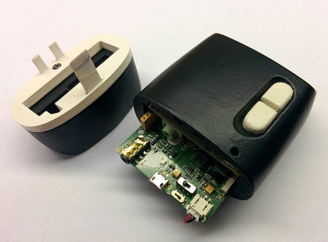
Everyone knows that in EXIF photos you can add a geotag with the coordinates of the location of the image. This is now no surprise. Any smartphone easily copes with this task. On the other hand, not every (even professional) camera has this option. It is clear that the smartphone has everything that is needed to determine geolocation, and the camera requires at least an additional GPS module. Yes, and professional photographers rarely need this. But what to do if you still need to shoot a lot and know where the pictures were taken?
For this we made our remote. It connects to the standard camera connector, which is specifically designed for this purpose. The user presses a button, the remote closes the optocoupler for shooting and records the time and coordinates. If the time on the camera is set correctly, then it will be easy to compare the pictures with the coordinates.
But in practice, it is much easier to install an application on a smartphone that records a GPS track continuously while shooting, and then do the same thing as with the remote control. Why then do a separate device?
In fact, the main goal of the project is not even the remote control itself, but to gain real experience with the LinkIt One board, to which we will return later.
The basis of the console is the LinkIt One board, for which I made a special shield for taking pictures.
From the hardware point of view, the consoles for photographing are extremely simple. They are connected to the camera with a jack-type connector with a diameter of 2.5 mm. There are three contacts in it - earth, half press and full press. In the console is a simple button that closes the signal contacts with the ground. Therefore, on our shield for photography, first of all, there is a dual-channel optocoupler PVT322 . She closes these contacts.
Secondly, I installed a three-color LED that allows you to understand the condition of the receiver. That is, at the start he needs time until he finds satellites and at this time shooting is impossible. The charge level is determined by the same LED.
Also on the shield are two buttons for controlling the remote (shooting and battery control), a connector for connecting the camera and a GPS antenna from the LinkIt One kit.

The scheme is extremely simple. I can only say that I connected all the loads (RGB-LED and optocoupler) through BCR108E6327 logical transistors. Schild's board attached at the end of the article, in case someone wants to repeat the device.
We also managed to make an unplanned case for him unplanned. When I was working on a project, I met an aspiring graphic designer who was interested in 3D printing and industrial design. Here is his profile in SketchUp's warehouse. Without hesitation, he agreed to help.
He, like me, used SketchUp for this, but at his much higher level. This program is quite simple, but armed with plug-ins, in the hands of a professional, it can work wonders. Look at the body of the resulting remote can be in the online viewer here .
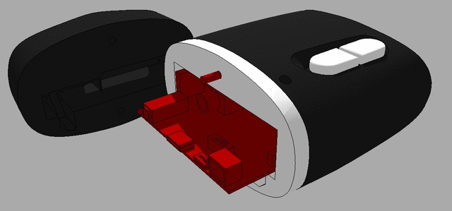
Of course, we printed it out, cleaned it up, painted it, collected it and got the following:
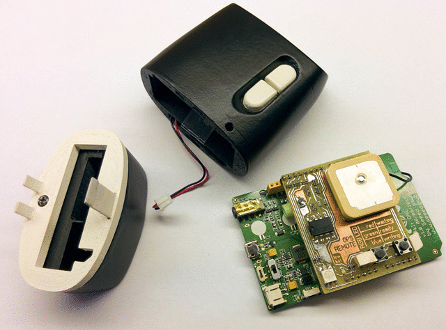
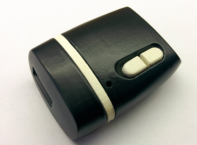
With the hull, over, there are problems. The fact is that the designer came to the rescue later than I did the electronics. The photo connector is recessed deep into the console, and the toggle switches on the LinkIt One itself are not available when the remote is closed. In general, the body was not perfect, but quite nice and usable.
Immediately after turning on, the remote determines its location. At this time, the indicator LED flashes red and shooting is not possible. After the position becomes known, the LED starts flashing green. Pressing the right button takes a picture, coordinates are recorded in the memory, and the LED for this time lights up in blue.
The second button is responsible for the battery. After pressing it for one second a green or red LED lights up. If green, then the charge is more than 20%, if red - then less.
There are two problems due to the hull. Firstly: you can get close to the power supply tumbler by opening the lid. It may be easier not to turn it off, but we have not checked how long the battery is enough. Secondly: the board has a switch responsible for the computer mode: either UART or Mass Storage. And in the Mass Storage mode, the program does not start when disconnected from the PC. This means that you need to switch this switch when you need to download data from the remote.
All this is easier to see once:
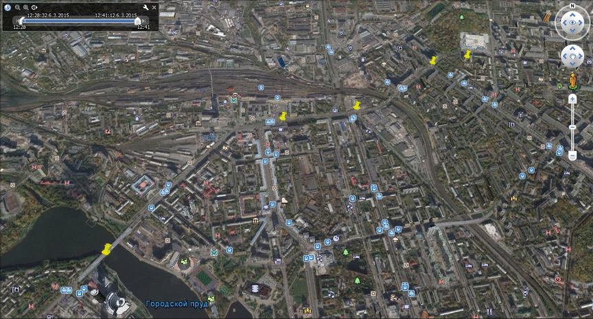
Remote parse NMEA messages that the receiver sends and saves them in kml format. The recorded file can be downloaded by connecting the console to a computer, and you can view the content in Google Earth:
And now a little more about the heart of the remote.
At first glance, this is just another Arduino clone, but when you start to understand, everything turns out to be much less prosaic.
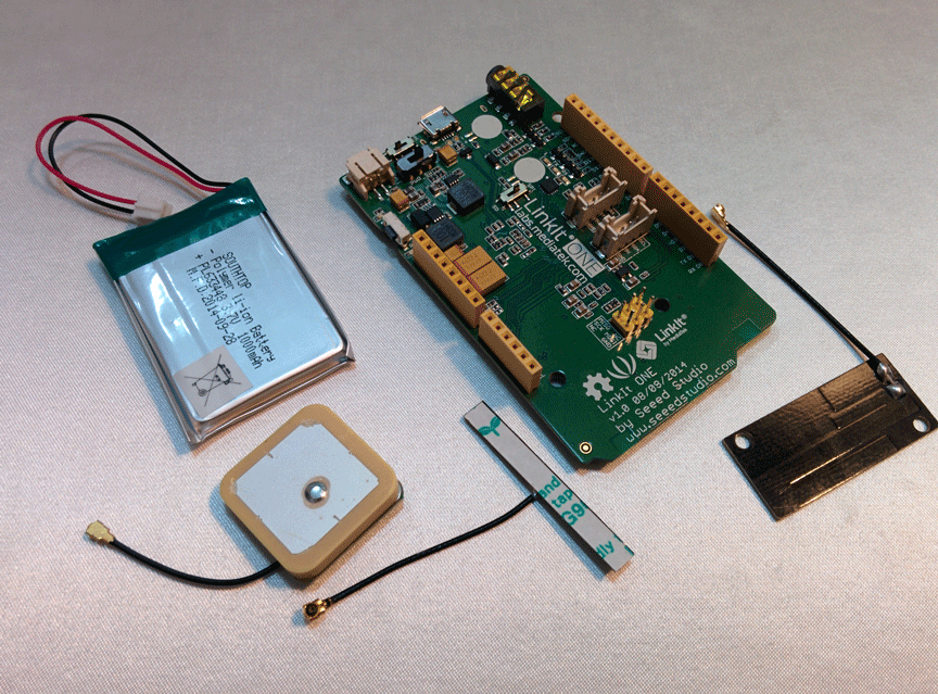
Details on technical specifications can be found on the wiki and in the Developer's Guide . I just list the distinctive features:
In fact, there is a lot of pleasant things on the board that are already implemented in the API. Work with GSM, GPS, Bluetooth, I2C, SPI, 3xUART, work as MP3 files, battery, etc. The idea of the board itself is that it already has everything you need. But because of this, LinkIt One is not very convenient in the context of controlling any external hardware in real time. Specialized RTOS runs on it, but the timings are still floating. Logic levels GPIO - 3.3V. Three analog inputs, two PWM outputs (and only servos can be connected to them). That is, there is a risk of iron that it is not compatible with some ready-made solutions.
Working with it is supposed to be in the Arduino IDE. To it you will need to install an additional SDK which implements some of the functions of the Processing / Wiring language and many special functions for LinkIt One. In fact, all software for this board is developed in C ++. Right in the environment you can see a lot of ready-made code examples. Documentation is over, while relatively little. For example, I could not find any description of the power supply circuit board, nor its overall dimensions. And Google constantly gives when searching for links to LinkedIn.
You can buy a fee on Seeedstudio.com for $ 79. The board is sold in a nice box with instructions, three antennas and a battery.
I also did a little benchmark.
Next, I will provide quick start instructions for Windows and Linux. This may seem interesting only to those who really will work with her or are planning to do it.
First of all, you need to upgrade the Arduino IDE to work with LinkIt One. Manufacturers recommend to download the SDK and the latest version of the Arduino IDE, and then run the SDK and specify the folder with the medium. But with the move, I did not succeed. Instead, I downloaded the already deployed environment for programming LinkIt One.
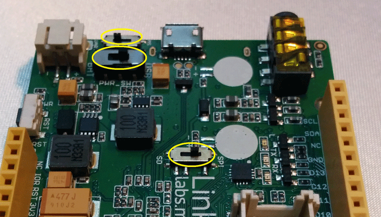
At the top of the board there are three switches responsible for the mode of operation of the board. The first switch sets the initialization method in the system (as a COM port or as USB Mass Storage). The second sets the power mode: USB or battery. The third is the connection to the SPI SD card or slot. Before connecting the board to the computer, you must set these switches as shown in the photo:
Then you can connect the board to the computer. Immediately after connecting, two unknown devices will appear in the device manager:

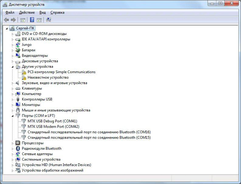
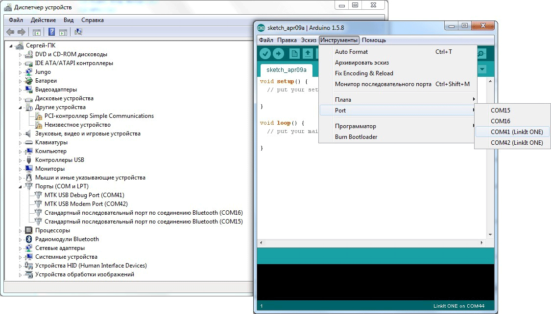
Now you need to install the driver. The installer is in the folder ... \ Arduino-LinkIt-ONE-IDE-master \ drivers \ mtk. Just run InstallDriver.exe and wait. Two COM ports will appear in the device manager at once:
This completes the installation. Just in case I updated the firmware of the board to the latest version. How to do this is described in the wiki (in short, you just need to run FirmwareUpdate.exe).
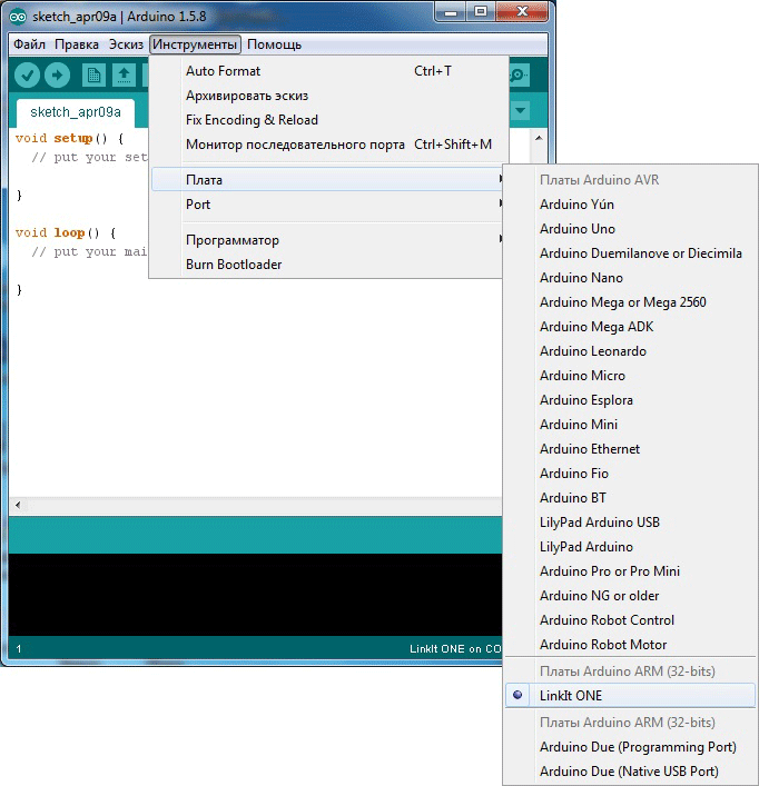
You can start loading an example with a flashing LED. Launch the Arduino IDE and select the LinkIt One board:
Now select the COM port. It is necessary to specify the port that is displayed in the Device Manager as Debug Port!
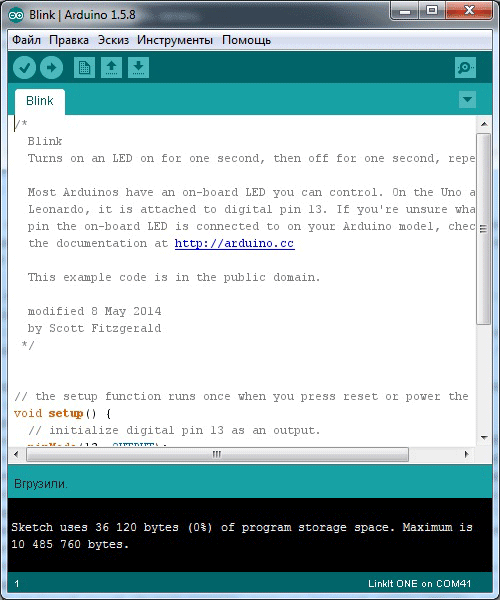
Then open the finished Blink example and click on the “Download” button. If everything is done correctly, the environment will issue a corresponding message about it (note the percentage of used memory):
After the download is complete, the user LED on the board will flash:

Mediatek only supports Windows, but you can also work under Linux if you wish. This will require:
This is all very inconvenient and seriously develop something in this mode does not work. But for one project for the evening this decision.
Overall, the experience with LinkIt One is positive. There are, of course, roughness. The feeling is that you are working with something slightly unfinished, as always when mastering something new. But on the other hand, it can really help to quickly launch even a relatively complex project.
Files to download:
Shield for LinkIt One
3D model of the case
Sample kml file
Source code of the console program
This is the only repository of articles from my site ( 1 and 2 ).
In order to get a “combat” experience with this controller, we have developed an uncomplicated console that connects to the SLR camera, takes pictures and records the coordinates of the shooting point.
In this article I will talk about the resulting device and share our impressions of working with LinkIt One.
')

The idea of creating a remote
Everyone knows that in EXIF photos you can add a geotag with the coordinates of the location of the image. This is now no surprise. Any smartphone easily copes with this task. On the other hand, not every (even professional) camera has this option. It is clear that the smartphone has everything that is needed to determine geolocation, and the camera requires at least an additional GPS module. Yes, and professional photographers rarely need this. But what to do if you still need to shoot a lot and know where the pictures were taken?
For this we made our remote. It connects to the standard camera connector, which is specifically designed for this purpose. The user presses a button, the remote closes the optocoupler for shooting and records the time and coordinates. If the time on the camera is set correctly, then it will be easy to compare the pictures with the coordinates.
But in practice, it is much easier to install an application on a smartphone that records a GPS track continuously while shooting, and then do the same thing as with the remote control. Why then do a separate device?
In fact, the main goal of the project is not even the remote control itself, but to gain real experience with the LinkIt One board, to which we will return later.
The hardware part of the remote for photography
The basis of the console is the LinkIt One board, for which I made a special shield for taking pictures.
From the hardware point of view, the consoles for photographing are extremely simple. They are connected to the camera with a jack-type connector with a diameter of 2.5 mm. There are three contacts in it - earth, half press and full press. In the console is a simple button that closes the signal contacts with the ground. Therefore, on our shield for photography, first of all, there is a dual-channel optocoupler PVT322 . She closes these contacts.
Secondly, I installed a three-color LED that allows you to understand the condition of the receiver. That is, at the start he needs time until he finds satellites and at this time shooting is impossible. The charge level is determined by the same LED.
Also on the shield are two buttons for controlling the remote (shooting and battery control), a connector for connecting the camera and a GPS antenna from the LinkIt One kit.

The scheme is extremely simple. I can only say that I connected all the loads (RGB-LED and optocoupler) through BCR108E6327 logical transistors. Schild's board attached at the end of the article, in case someone wants to repeat the device.
Housing for remote
We also managed to make an unplanned case for him unplanned. When I was working on a project, I met an aspiring graphic designer who was interested in 3D printing and industrial design. Here is his profile in SketchUp's warehouse. Without hesitation, he agreed to help.
He, like me, used SketchUp for this, but at his much higher level. This program is quite simple, but armed with plug-ins, in the hands of a professional, it can work wonders. Look at the body of the resulting remote can be in the online viewer here .

Of course, we printed it out, cleaned it up, painted it, collected it and got the following:


With the hull, over, there are problems. The fact is that the designer came to the rescue later than I did the electronics. The photo connector is recessed deep into the console, and the toggle switches on the LinkIt One itself are not available when the remote is closed. In general, the body was not perfect, but quite nice and usable.
Remote operation
Immediately after turning on, the remote determines its location. At this time, the indicator LED flashes red and shooting is not possible. After the position becomes known, the LED starts flashing green. Pressing the right button takes a picture, coordinates are recorded in the memory, and the LED for this time lights up in blue.
The second button is responsible for the battery. After pressing it for one second a green or red LED lights up. If green, then the charge is more than 20%, if red - then less.
There are two problems due to the hull. Firstly: you can get close to the power supply tumbler by opening the lid. It may be easier not to turn it off, but we have not checked how long the battery is enough. Secondly: the board has a switch responsible for the computer mode: either UART or Mass Storage. And in the Mass Storage mode, the program does not start when disconnected from the PC. This means that you need to switch this switch when you need to download data from the remote.
All this is easier to see once:
Remote parse NMEA messages that the receiver sends and saves them in kml format. The recorded file can be downloaded by connecting the console to a computer, and you can view the content in Google Earth:

And now a little more about the heart of the remote.
What is LinkIt One?
At first glance, this is just another Arduino clone, but when you start to understand, everything turns out to be much less prosaic.

Details on technical specifications can be found on the wiki and in the Developer's Guide . I just list the distinctive features:
- 260MHz ARM Processor with 16MB Flash and 4MB RAM
- Slot for installing an SD memory card up to 32GB
- Built-in modules with external antennas: WiFi, Bluetooth, GPS / GLONASS, GSM (there is a SIM card slot on the board)
- Powered by 1Ah battery. This is done well: it charges from USB, and the API lets you know the remaining charge
- Audio jack. Headphone and microphone
- Arduino compatibility. More on this below.
In fact, there is a lot of pleasant things on the board that are already implemented in the API. Work with GSM, GPS, Bluetooth, I2C, SPI, 3xUART, work as MP3 files, battery, etc. The idea of the board itself is that it already has everything you need. But because of this, LinkIt One is not very convenient in the context of controlling any external hardware in real time. Specialized RTOS runs on it, but the timings are still floating. Logic levels GPIO - 3.3V. Three analog inputs, two PWM outputs (and only servos can be connected to them). That is, there is a risk of iron that it is not compatible with some ready-made solutions.
Working with it is supposed to be in the Arduino IDE. To it you will need to install an additional SDK which implements some of the functions of the Processing / Wiring language and many special functions for LinkIt One. In fact, all software for this board is developed in C ++. Right in the environment you can see a lot of ready-made code examples. Documentation is over, while relatively little. For example, I could not find any description of the power supply circuit board, nor its overall dimensions. And Google constantly gives when searching for links to LinkedIn.
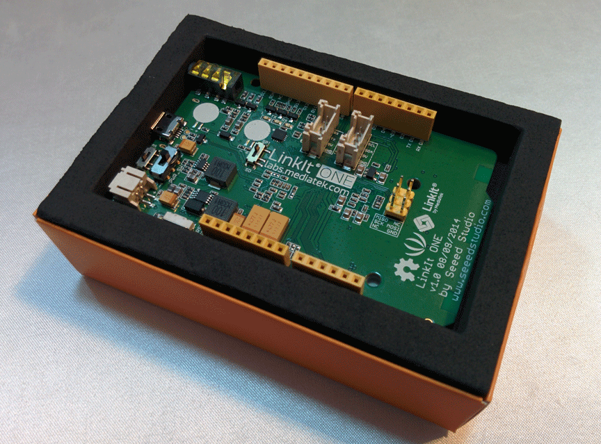
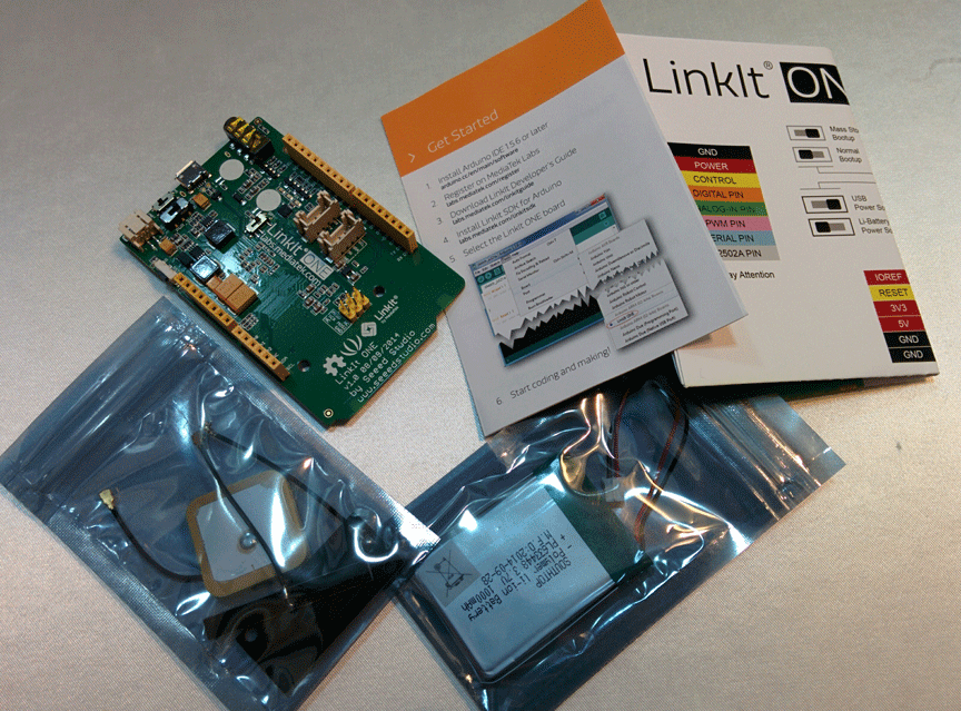
You can buy a fee on Seeedstudio.com for $ 79. The board is sold in a nice box with instructions, three antennas and a battery.
Photos with a box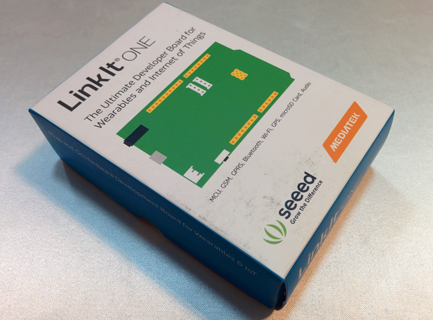


I also did a little benchmark.
LED flashing frequency
I understand that it is impossible to draw any conclusions about the hardware or software, according to the results of such a test, but I decided to check with what frequency the leg would twitch if I switch it with the digitalWrite function without delay.
The author of this post checked that the MK with Arduin's firmware does it with a frequency of 210 kHz, and that programmed with normal means - 1.6 MHz. Under the same conditions, LinkIt One showed me 312 kHz.
The author of this post checked that the MK with Arduin's firmware does it with a frequency of 210 kHz, and that programmed with normal means - 1.6 MHz. Under the same conditions, LinkIt One showed me 312 kHz.
Next, I will provide quick start instructions for Windows and Linux. This may seem interesting only to those who really will work with her or are planning to do it.
Hello World for LinkIt One for Windows
First of all, you need to upgrade the Arduino IDE to work with LinkIt One. Manufacturers recommend to download the SDK and the latest version of the Arduino IDE, and then run the SDK and specify the folder with the medium. But with the move, I did not succeed. Instead, I downloaded the already deployed environment for programming LinkIt One.
At the top of the board there are three switches responsible for the mode of operation of the board. The first switch sets the initialization method in the system (as a COM port or as USB Mass Storage). The second sets the power mode: USB or battery. The third is the connection to the SPI SD card or slot. Before connecting the board to the computer, you must set these switches as shown in the photo:

Then you can connect the board to the computer. Immediately after connecting, two unknown devices will appear in the device manager:

Now you need to install the driver. The installer is in the folder ... \ Arduino-LinkIt-ONE-IDE-master \ drivers \ mtk. Just run InstallDriver.exe and wait. Two COM ports will appear in the device manager at once:

This completes the installation. Just in case I updated the firmware of the board to the latest version. How to do this is described in the wiki (in short, you just need to run FirmwareUpdate.exe).
You can start loading an example with a flashing LED. Launch the Arduino IDE and select the LinkIt One board:

Now select the COM port. It is necessary to specify the port that is displayed in the Device Manager as Debug Port!

Then open the finished Blink example and click on the “Download” button. If everything is done correctly, the environment will issue a corresponding message about it (note the percentage of used memory):

After the download is complete, the user LED on the board will flash:

Working with LinkIt One for Linux
Mediatek only supports Windows, but you can also work under Linux if you wish. This will require:
- Install Arduino IDE
- Download the SDK for LinkIt One (although it is written that it is only for Windows) and install it using wine. In the folder, the installer checks for the presence of arduino.exe, it will suit an empty file with the same name
- Write your program and click "Check"
- After that, the compiler will produce some number of errors related to the fact that some source codes of libraries from the SDK include header files in the wrong case (for Windows, the register does not matter)
- Connect LinkIt One in memory card mode to computer
- Find the MRE folder on the removable disk and upload the * .vxp firmware file there. The autostart.txt file in the root indicates the path to the firmware that will be executed.
- Switch the board to UART mode and restart with the button
- Watch the firmware run
This is all very inconvenient and seriously develop something in this mode does not work. But for one project for the evening this decision.
Conclusion
Overall, the experience with LinkIt One is positive. There are, of course, roughness. The feeling is that you are working with something slightly unfinished, as always when mastering something new. But on the other hand, it can really help to quickly launch even a relatively complex project.
Files to download:
Shield for LinkIt One
3D model of the case
Sample kml file
Source code of the console program
This is the only repository of articles from my site ( 1 and 2 ).
Source: https://habr.com/ru/post/259247/
All Articles