Sensors and microcontrollers. Part 2. Climate control
 Let us continue the story about the sensors and in this part we consider the various sensors of the most popular DIY-community types - these are numerous temperature sensors and humidity sensors. In addition, we will touch the air pressure sensors and the presence of gases. We give a description of the nomenclature of the sensors and refer to the useful literature.
Content
Part 1. Mat. part. It considers a sensor that is not tied to any particular measured parameter. The static and dynamic characteristics of the sensor are considered.
Part 2. Climate control sensors. It discusses the features of working with sensors of temperature, humidity, pressure and gas composition
Part 3. Sensors of electrical quantities. In it, I touch the measurement of current and voltage
5. temperature sensors
No project on automatic climate control systems can do without a temperature sensor whose main task is to produce the required object with the required accuracy, be it indoor air, cooling fluid, grilled steak or molten metal (In climate control, yeah).
5.1 Thermocouples
Generating temperature sensors, which are two conductors of different materials, soldered at one end with each other.
The main advantage of thermocouples is their wide temperature range. Limited, in fact, by absolute zero and the melting point of metals — that is, it can measure there. Where other sensors are simply powerless - from -270 to +1800 degrees Celsius and above.
Thermocouples are different and, depending on the type of materials used, have a different range of operating temperatures.
Their design also depends on the application. For example, in one of the laboratories of my native department there were such 200-300mm drunks lying around:
')

Figure 1 Type K thermocouple for resistance furnaces
And this is how all known K-type thermocouples look, which come complete with multimeters (photo from my collection):
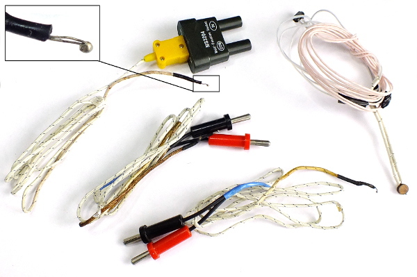
Figure 2: Type K thermometers for multimeters.
The following types of thermocouples with their composition, letter designation and operating range are listed in GOST R 8.585-2001 (the thermopower coefficient for 25 degrees is shown in brackets):
- platinum-platinum - TPP13 - Type R, range -50 +1600 C (9µV / C).
- platinum-platinum - TPP10 - Type S, range -50 +1600 C (6µV / C).
- platinum-rhodium-platinum-rhodium - TPR - Type B, range 0 +1800
- iron-constantan (iron-copper-nickel) TFA - Type J, range -210 +1200 (52mkV / C)
- copper-constantan (copper-copper-nickel) TMKn - Type T, range -270 +400 (41µV / C)
- Nihrosil-nisilovye (nickel-chromic nickel-nickel-silicon) TNN - Type N, range +270 +1300 (27mkV / C)
- chromel-alumel - THA - Type K, range -270 +1372 (41µV / ).
- chromel-constantan THKH - Type E, range -270 +1000 C (61mkV / C).
- chromel-copel - THK - Type L, range -200 +800
- Copper Copper - TMK - Type M, range -200 +100 C
- Silh-silinovye - TSS - Type I (not represented in GOST, is on Wikipedia)
- tungsten and rhenium - tungstennee - TVR - Type A-1, A-2, A-3, range 0 +1800, (+2500 for A-1) C.
By themselves, they are high-precision sensors (accuracy up to ± 0.01 degrees), but this accuracy is very difficult to obtain.
The sensors are based on the thermoelectric effect discovered in 1821 by the German physicist Thomas Seebeck. Its essence lies in the fact that if the junctions of two dissimilar materials forming a closed electrical circuit have different temperatures T1 and T2, then an electric current appears in the circuit, the direction of which depends on the sign of the temperature difference.
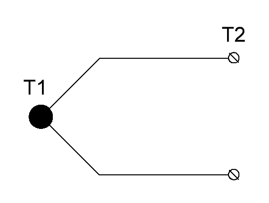
Figure 3: Thermocouple.
But here the first problem appears - the emf depends on the temperature difference between the hot and cold junctions, so the temperature of the cold junction should be known with the necessary accuracy to determine the temperature of the hot end.
A problem is added by the fact that, in fact, the points of connection of the thermocouple to the measuring system are also the junction points of two different metals, which introduces its own error. Therefore, we place both cold ends together in order to equalize their temperature and we will monitor it with another sensor:
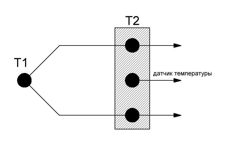
Figure 4: Cold Junction Software Compensation
In this case, by measuring with an ultimate accuracy with an absolute temperature sensor the temperature of the cold junction, we can programmatically compensate for it. Why can't I use one absolute sensor right away? Show me another sensor that can measure the temperature of the molten metal.
If there is no absolute sensor at hand, but it is necessary to measure, take another thermocouple, connect it in series in antiphase and place it on Wednesday, the temperature of which we know - for example, water with ice:
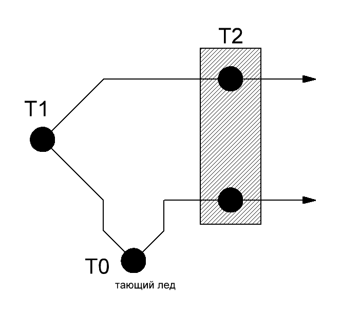
Figure 5: Cold Junction Hardware Compensation
But in my opinion, in the presence of widely available accurate temperature sensors, it is a little non-technological to use a tank with melting water that requires constant monitoring. Therefore, in the documentation there are variants of thermostatically controlled cold junctions in which the set temperature is maintained with the help of an accurate thermostat.
By the way, the thermostatic element is not such a rarity.
For example, the “hyacinth” reference signal generators standing in the Soviet measuring equipment are a quartz resonator wrapped with high resistance wire and placed in a small Deward vessel in which a certain temperature is maintained. As a result, frequency stability up to 7-8 decimal places is achieved.
We dealt with the problem of relativity, now we will try to take readings from the thermocouple. And here two more problems await us:
Problem number one - thermoEMF is measured in microvolts. For example, for a type K thermocouple, the temperature coefficient is 41 µV / degree. This means that millivolts will smell only degrees through 25 temperature differences.
Let me remind you of the last part that a 12-bit ADC with a reference voltage of 3.3V has a sensitivity of 800 µV. i.e. in our case 20 degrees / division. Not bad, however, error. Of course, you need to take into account the small operating range of the output voltage of the thermocouple and put amplifiers on the base of an op amp, or include amplification in the ADC itself.
There will arise other difficulties such as the accuracy of digitizing the ADC, the inherent noise of the analog paths of the OU and the ADC, and so on.
We will follow one truth - to use precision and low-noise OU and ADC. In the list of additional literature there are many different options for connection schemes. However, one of the most common circuits in most mass measuring devices is using a thermistor:
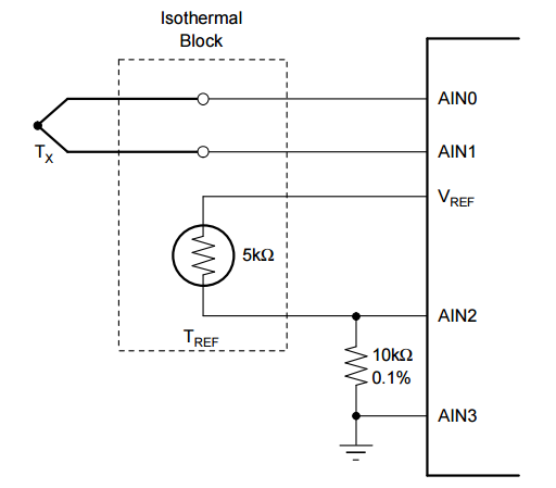
Figure 6: Using a thermistor to compensate for the cold junction temperature
Problem number two - thermocouple nonlinear. The nonlinearity is as follows:
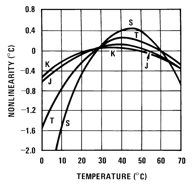
Figure 7: Thermocouple Nonlinearity
But the blessing is everyone in the course of this non-linearity, each measured measurements were accurately entered into the tablet and calculated the exact coefficients of the polynomials of the form:
 (one)
(one)To calculate the temperature based on the EMF value and vice versa:
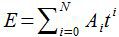 (2)
(2)For each type of thermocouple, all the necessary coefficients of approximating polynomials for temperatures relative to 0 degrees Celsius are carefully listed in GOST 8.585-2001. Here is a list of polynomial coefficients for a common K-type thermocouple:
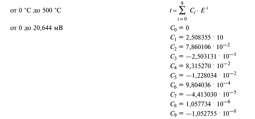
Figure 8: A list of polynomials for a type K thermocouple in the temperature range from 0 to 500 degrees Celsius
In principle, it’s not difficult to calculate the total value of work, but if your cold junction dangles in the air at an unknown temperature - who needs it?
As a result, the thermocouple is one of the best sensors for accurate measurement of very hot or very cold things.
And in my favorite childhood book, Wojciechowski's Radio Electronic Toys, you can find a description of the design of the thermogenerator, from which it is proposed to power, for example, a transistor radio. And on Mars from a thermogenerator of a similar design, only the smallest more technologically, is powered by the rover Curiosity - On Geektimes there is a survey post about RTGs .
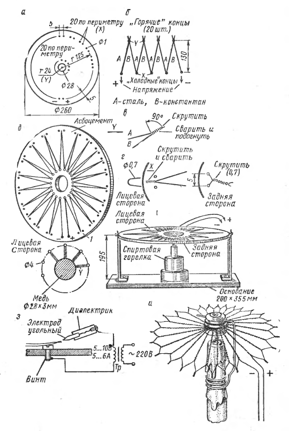
Figure 9: Temroelectric 0.6V 8mA battery
A moment of senseless and merciless practice.
We have a debug board on an ATmega1280 microcontroller, a pair of thermocouples and a desire to measure the temperature with good accuracy. And we will not succeed.
The ADC of the controller is 10-bit, the minimum reference voltage can be set to 1.1V.
Then the sensitivity of the ADC will be:
 (3)
(3)Analog ADC inputs allow operation in differential mode with a maximum gain of 200 times. However, with such an increase, the reference voltage can only be 2.56V, and only 7 digits remain effective. Then the sensitivity of the ADC will be:
 (four)
Which is about 2.5 times less than the sensitivity of a type K thermocouple (41 µV). i.e. Theoretically, the accuracy of the measuring path will be no better than ± 2.5 degrees. Practically, noise will prevent us. And they are according to table 31-8 data protection of whole + -10 characters - that is, the final accuracy will be no better than + -25 degrees. Hehe. This we have not yet taken into account two half-meter wires to thermocouples, the lack of proper filtering of analog power and the power of the entire system from a rather noisy USB. Give Scotch at least ± 50 degrees to pack.
Let us write a program that will work on interrupts (I sketched it for one of the comments ). Use the Arduino environment as a loader:
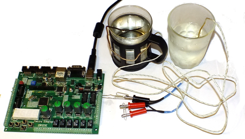
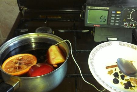
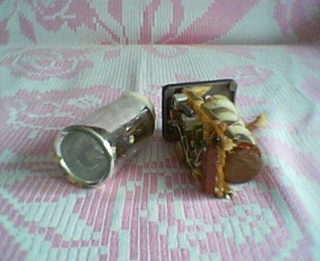
Figure 10: A full-scale experiment with two thermocouples, glasses and paper clips
Source:
void setup() { autoadcsetup(); } void loop() { } float coeff[] = {0, 2.508388e1, 7.860106e-2, -2.503131e-1, 8.315270e-2, -1.228034e-2, 9.804036e-4, -4.413030e-5, 1.057734e-6, -1.052755e-8 }; void autoadcsetup(){ //set up TIMER0 to 61Hz //TIMER0_OVF will be the trigger for ADC /*normal mode, no prescaler 16MHz / 256 /1024 = 61 Hz*/ TCCR0B = (1 << CS02) | (1 << CS00);//timer frequency = clk/1024 //set ADC. ADMUX = (1 << MUX3) | (1 << MUX1)| (1 << MUX0) | (1 << REFS1)| (1 << REFS0);//10-bit mode, ADC9-ADC8 channel, Gain 200, 2.56V ref ADCSRA = (1 << ADEN) | (1 << ADATE) | (1 << ADIE) | (1 << ADPS2)| (1 << ADPS1)| (1 << ADPS0);//TUrn ADC On, trigger enable, Interrupt enable, sysclk/128=125kHz_ADC_clk=9.6kHz conv freq(13ticks per conversion) ADCSRB = (1<< ADTS2) | (1 << MUX5);//Auto trigger source //set UART to 8-n-1 1Mbod: UBRR0H = 0;//9600(use Examples of Baud Rate Setting table from datasheet) UBRR0L = 103;//9600 UCSR0B = (1<<TXEN0);//enable Transmitter UCSR0C = (3<<UCSZ00);//8-bit mode } int32_t result=0; float t=0; ISR(ADC_vect){ if( ( UCSR0A & (1<<UDRE0)) ){ //calc: t=0; result = (ADCH >>1)*2560/512;//calc voltage in mV float edc = static_cast<float>(result);//convert to float for (uint8_t i = 0; i < 10; i++){ t += coeff[i] * pow (edc, i); } UDR0 = static_cast<uint8_t>(t); } } For boiling water around one thermocouple and glass with melting ice around the other at the exit is solid porridge with an average value of the first two lines of 124 degrees, which is a very good result - we will assume that we are within the accuracy of + -25 degrees.
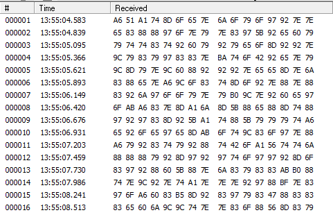
Figure 11: Raw Output
Of course, this hack does not represent any practical significance, and more accurate ADCs must be used to measure the temperature using a thermocouple. For example, the ADuCM360 microcontroller has a good integrated ADC, and it is designed specifically for such small input signals. There are specialized external ADCs for thermocouples - for example, Maxim Integrated manufactures several thermocouple chips - MAX31850, MAX31851, MAX31855, MAX31856 . Analog Devices has drivers. The budget option will be the use of pre-amplifiers on low-noise op amps for our ADC. I showed good results LMP2011.
5.2 Resistance thermometers and thermistors
As is known, the resistance of the metal varies with the ambient temperature. This effect is used to conduct highly accurate (up to thousandths of a degree) temperature measurements using resistance thermometers. Being made not from metal, but from a semiconductor, we get a thermistor.
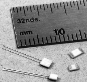
Figure 12: Honeywell Platinum RTD
Resistance thermometers allow you to work in a fairly wide range of temperatures - from -200 to 850 degrees.
The resistance thermometer has two main characteristics:
- Base resistance at a certain temperature. Recommended - 10, 50, 100, 500, 1000 Ohms ...
- Temperature coefficient of resistance in thousandths in propromille per degree Kelvin (ppm / K).
Temperature coefficient of resistance is the ratio of the relative change in resistance to temperature change:
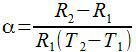 (five)
Thus, knowing the current resistance of the thermistor and knowing its TKS and nominal temperature, you can calculate the current temperature:
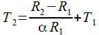 (6)
(6)Thermometers of resistance have GOST R 8.625-2006, in which thermometers from platinum (TKS = 0.00385 and 0.00391), as well as from copper (TKS 0.00428) and nickel (TKS 0.00617) are normalized. Nominal resistance for thermometers is resistance at a temperature of 0 degrees. Like thermocouples, resistance thermometers have some non-linearity, but the polynomial coefficients are carefully listed in the GOSte. By the way - much simpler than for thermocouples.
For example, for a platinum thermometer with TKS = 0.00385 and a measurement range from -200 to 0 degrees there will be an equation of the form:
 (7)
(7)And for the range of 0-850 degrees:
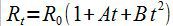 (eight)
With the following coefficient values:
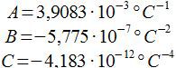 (9)
(9)One of the most popular is the standard platinum thermometer series 700 from Honeywell. Although the cost of platinum thermometers are not cheap - from $ 5 or higher, depending on the temperature range and accuracy of the device.
Measure resistance can be a variety of methods. The simplest and recommended GOST is a measuring bridge with a voltage source. On the other hand, connecting to a current source and using the differential input of the ADC will give a linear measurement.
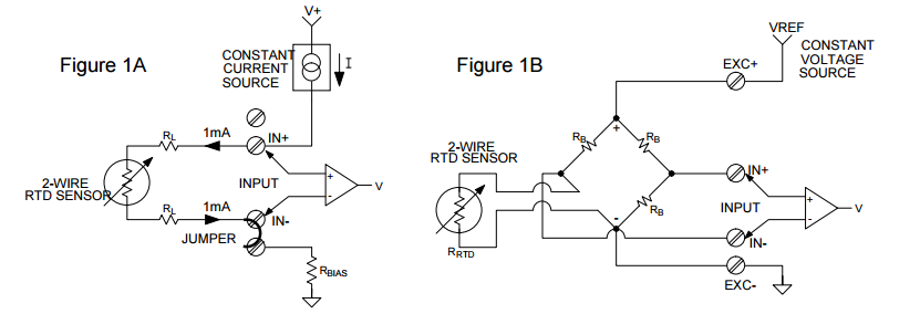
Figure 13: Different ways to connect two-wire RTD
I quote Comrade Stross from the comments on the previous part:
The bridge can be considered as two resistive dividers connected in parallel. One of them sets the "reference voltage" for the second. And thus, when using a bridge, with your differential ADC, you will measure the voltage on the divider not relative to zero, but relative to a certain support. This will have a good effect on sensitivity - you can set the ADC to a higher preamp ratio and ensure that the working range of the ADC will correspond to a narrow range of resistances.
On the other hand, your ADC in input gain modes should not make noise like a lone stream flowing from a fuji tractor
In the annex to the section there are many useful links on connecting RTD and ways to improve accuracy.
One of the problems of metallic resistance thermometers is low TKS, due to which a measuring path with high sensitivity is needed. But this is only a constructive problem - measuring resistance with high accuracy, unlike very low currents and voltages, is not difficult.
If we do not need high accuracy and enough ± 1-2 degrees, then you can use semiconductor thermistors, which have orders of magnitude higher TKS. For example, thermistors of the KTY84 series from NXP have TKS = 0.61. On the other hand, thermistors have a smaller operating temperature range of about -40 = 300 degrees.
And thermistors are much more non-linear. But again, the data of TKS and nominal resistance for different values of temperature are carefully given in data boards:
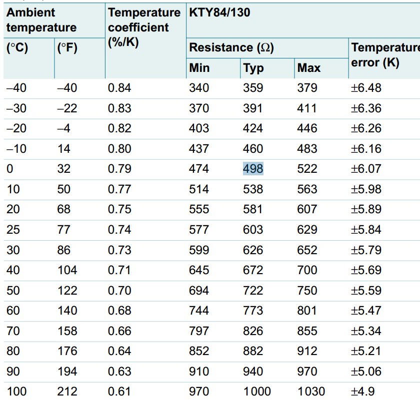
Figure 14: Correspondence table of TCS, nominal resistance and temperature
According to this table, it will not be difficult to construct a piecewise linear function and use it to determine resistance.
5.3 Linear Analog Converters

Figure 15: LM35DZ linear analog sensor
Let's move on to more integrated solutions. Consider an analog linear temperature sensor chip. This microcircuit is connected to a voltage source and gives the output an analog signal, linearly dependent on temperature with a slope of 10-20 mV / K. The range of measured temperatures is much narrower than that of the previously presented sensors and averages -40 + 125 degrees. Since our simple 10-bit ADC has a sensitivity of 1 mV, it is more than enough to read the readings from this sensor.
Another useful property of these sensors is that their output voltage does not depend on the supply voltage, which can vary widely - for example, for the LM35 sensor from National Semi, the supply voltage range is 4-30V. The accuracy of the sensors is 1-2 degrees. It looks like a graph of the accuracy of the sensor depending on the temperature:
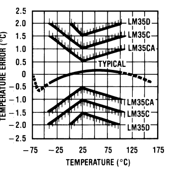
Figure 16: Sensor Accuracy vs. Temperature
There is nothing more to say about this sensor, so we are diverging.
5.4 Digital temperature sensors
Digital temperature sensors behind their huge range of conceal convenient integrated solutions that provide the ability to obtain temperature readings in finished form through digital interfaces.
As a rule, digital temperature sensors are connected via SPI and I2C interfaces. As for me, temperature sensors are low-speed devices and SPI waste on them.
As an example, consider the SHT10 combined temperature and humidity sensor:
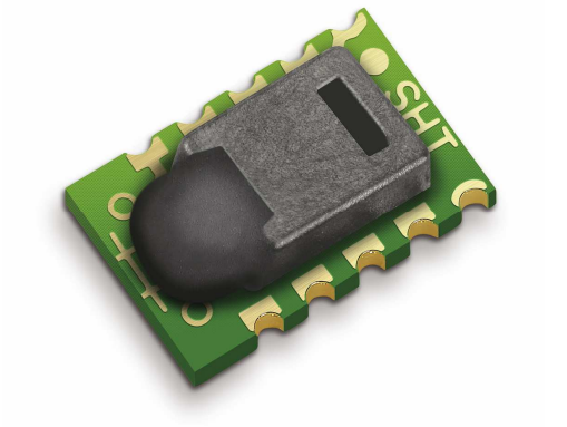
Figure 17: Sensor SHT10 general view
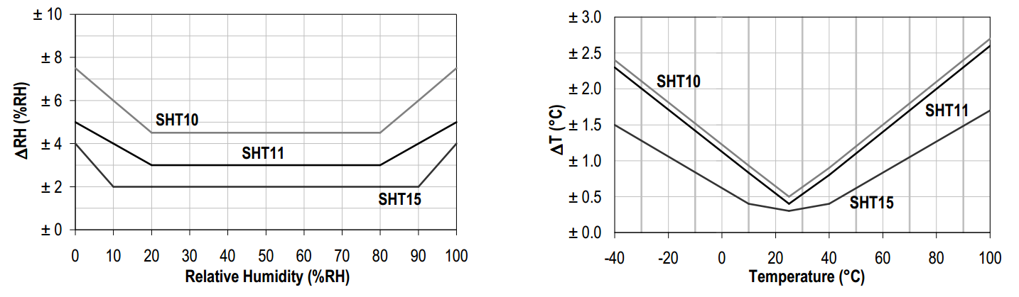
Figure 18: Sensor Error
But this sensor is not without a jamb - its interface is “optimized”. Type in order to make it easier to count. And it can not be addressed as an I2C device.

Fortunately, the sensor allows you to connect yourself together with other devices, and you just need a software switch protocol communication. We’ll dwell on it a bit more:
To start a command transfer, you must transfer the starting sequence:
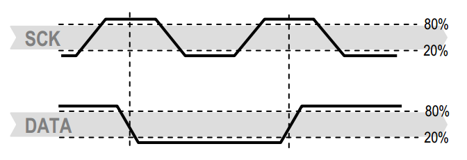
Figure 19: Starting Sequence
After the start sequence, the command byte is transmitted, consisting of 0 address bits (only address 000 is supported) and 5 instruction bits.
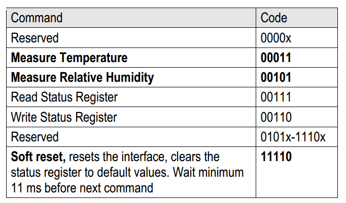
Figure 20: Command List
After sending a command to measure temperature or humidity, depending on the bit width of 8, 12 or 14 bit measurements, the measurement procedure will take 20, 80 or 320 ms. Upon completion of the measurement process, the sensor will attract the DATA line to zero and go to sleep. As soon as the controller receives this signal, by clocking the SCK line, it is possible to receive two data bytes and a checksum byte (if it is activated), and at the end of each byte reception it is necessary to attract the controller to attract the ground to zero. The data is transmitted with the right hand out, i.e. For a 14-bit value, the most significant data bit will appear only on the 5th tick of the SCK line. For details, I send to the data sheet.
The temperature sensor has a linear characteristic and the resulting sensor value is recalculated taking into account the supply voltage and the slope of the characteristic:
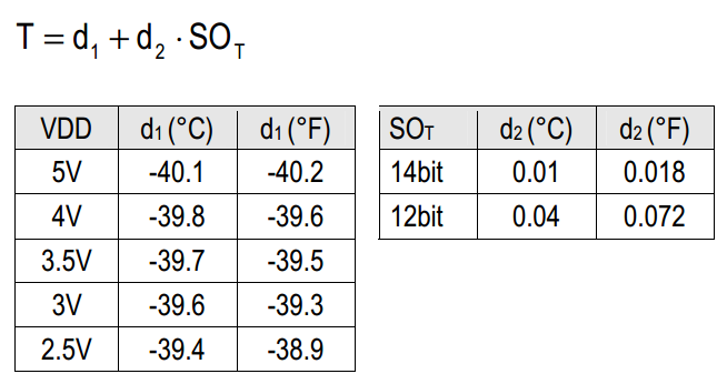
Figure 21: Calculate Temperature
Of course, there are temperature sensors with a normal I2C interface. For example, LM75A from NXP.
Its data reading diagram follows the basic I2C principles:
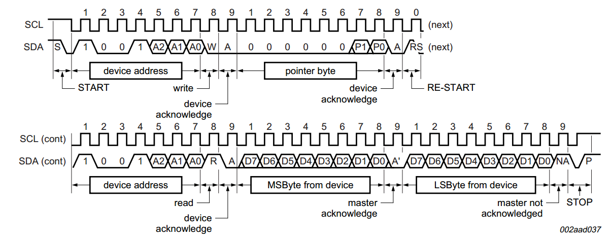
Figure 22: Reading Temperature Data from the LM75
This is an 11-bit sensor, with a resolution of 0.125 degrees Celsius, the output data is stored in two data registers with a specific address. Using the I2C commands for our device, which has the address 1001XXX (three lower bits are set by the user and allow you to connect up to 8 such sensors to one bus), we set the register address pointer from which we start reading and using the read command we read two registers. The resulting sign value is multiplied by 0.125 and we get the final temperature value in degrees Celsius. Conveniently.
5.5 DS18B20
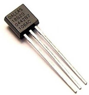
Figure 23: DS18B20 Digital Sensor
This sensor should be given special attention.This is a 12-bit temperature sensor with an operating range of -55 + 125 degrees Celsius, connected via the 1-wire protocol. Its main advantage is that you can hang dozens of these sensors on one line and they will all work. The sensor is very accurate ± 0.5 degrees, but slow - the measurement time is 750ms.
Inside the sensor 9 registers, registers 0 and 1 store the value of the measured temperature, registers 2 and 3 can be used as general purpose memory, 4 registers stores the configuration according to the following table:

Figure 24: Assignment of the configuration register bits The
CRC is the ninth byte of the register memory. Calculated using the following formula based on the first 8 registers:
 (ten)
(ten)In order to run the temperature calculation command, you must send the command 0x44. Upon completion of the measurement process, the data will lie in the first two bytes of the register memory until the next measurement. Reading 9 bytes of register memory data is performed by issuing the command 0xBE.
In general, this sensor, having a very affordable price, allows, using long lines of communication, to organize a network of sensors covering one or another area. For example, you can mesh sensors in a greenhouse and monitor the temperature gradient inside it.
5.6 IR temperature sensor
This review would be incomplete without contactless IR temperature sensors. I casually mentioned it when I talked about the CC3200-launchxl board - there is such a sensor installed there.
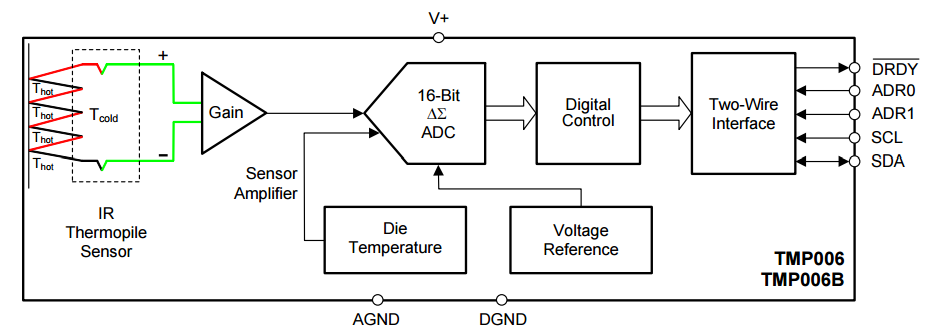
Figure 25: IR thermal sensor
These sensors consist of a thin plate. Absorbing IR radiation, as a result of which it is heated, which is detected by the thermal sensors described above. For example, in the Texas Instruments TMP006 sensor, judging by the image inside the set of series-connected thermocouples, the signal from which is removed and converted to digital with access via I2C. Hostess for a note - this sensor measures the temperature from -40 to +125 degrees with an accuracy of ± 1.5 degrees. I, as the owner of this sensor on the debug board, am gradually playing with it.
There are analog solutions. For example, TPS333 sensors from Excelitas have an internal thermistor inside.
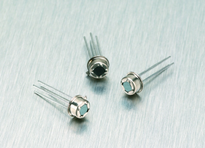
Figure 26: TPS333 sensors from Excelitas Of
course, the most interesting are contactless IR arrays, on the basis of which thermal imagers are made. For example, the D6T-44L-06 sensor from Omron for $ 35 is a 4x4 bit matrix, with which you can measure the temperature from 5 to 50 degrees at a distance of up to 3 meters.

Figure 27: Detection area.
Here is a cool video presentation from the manufacturer:
The resolution of the sensor is of course so-so, and the temperature range is not very large, but such a matrix has its own niche, and the price pleased me personally. You can take note.
5.7 Further reading
- ww1.microchip.com/downloads/en/AppNotes/00844a.pdf
- cds.linear.com/docs/en/application-note/an28f.pdf
- www.analog.com/library/analogDialogue/archives/44-10/thermocouple.html
- www.ti.com/lit/an/snoa663b/snoa663b.pdf
- www.ti.com/lit/an/sbaa134/sbaa134.pdf
- www.ni.com/tutorial/7115/en
- www.acromag.com/sites/default/files/RTD_Temperature_Measurement_917A.pdf
- newton.ex.ac.uk/teaching/CDHW/Sensors/an046.pdf
- www.analog.com/library/analogdialogue/archives/47-09/3_wire_rtd.pdf
- www.ti.com/lit/ug/slau520a/slau520a.pdf
6
No climate control system will be complete without measuring the relative humidity of the air, since the comfort of a person in a controlled room depends on it. I think many people are familiar with the comfort zone graph:
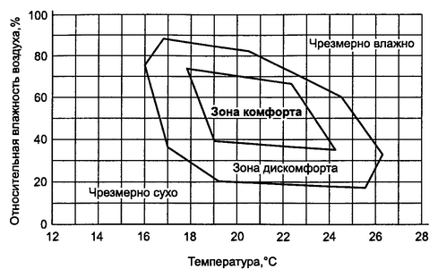
Figure 28: The comfort zone in
Russia In Russia, acceptable values for temperature and humidity in residential areas are regulated by SanPiN 2.1.2.2645-10 “Sanitary and epidemiological requirements for living conditions in residential buildings and rooms” (Appendix 2).
The task of the humidity sensors is to determine the relative humidity of the air. Relative humidity of air is the ratio of the partial pressure of water vapor in the air to the equilibrium pressure of saturated vapor at a given temperature:
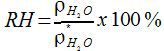 (eleven)
Where
 - partial pressure of water vapor in the air,
  - equilibrium pressure of saturated steam.
There are several ways to measure air humidity.
Of course it is worth mentioning the classic psychrometers - the assembly of a dry and wet thermometer, the difference in the readings of which fairly accurately determines the current humidity of the air. Nobody forbids to take two temperature sensors, one of them to supply wet cotton wool and on the basis of their readings to calculate the humidity.
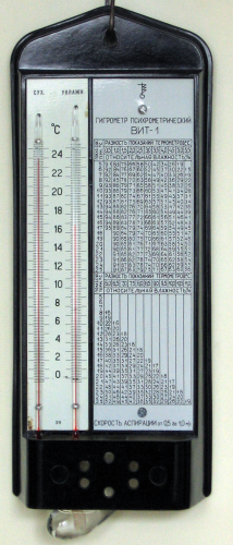
Figure 29: Psychrometer
Next are mechanical hygrometers, where the defatted hair or polymer film acts as a sensitive element, changing its length depending on humidity.
But we are more interested in solutions with an electrical signal at the output.
Such sensors react to moisture by changing the capacity or resistance of a hygroscopic material saturated with moisture in an amount proportional to the partial vapor pressure of the measured air. Widely received capacitive sensors. Therefore, only we will consider them.
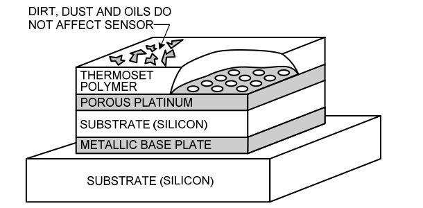
Figure 30: Moisture Sensor Structure.
6.1 Humidity sensors with capacitive output
The easiest in nature sensor. It is a capacitor with variable capacitance. The capacity of such a condenser is primarily dependent on humidity. But not the last indicator is the air temperature. For example, for a Honeywell HCH-1000 series sensor, the sensor sensitivity averages 0.6 pF /% RH. In this case, the temperature coefficient is 0.16 pF / degree. Clearly, the capacitance change graph looks like this:
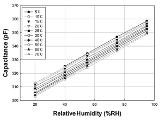
Figure 31: HCH-1000 sensor capacitance variation
Unlike resistance. Capacity is much more difficult to measure. Exact professional devices - immitance meters (RLC-meters) - not the cheapest equipment.
A simple way to measure capacitance is to determine the rate of charge and discharge of an RC chain. Determining the charge time constant with the required accuracy and knowing the exact resistance of the resistor, we can determine the capacitance of the capacitor.
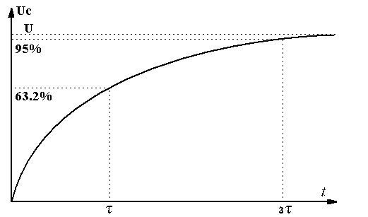
Figure 32: capacitor charge
Since our capacitance varies between 300-360pF, to obtain a time constant of 1-2ms (which will be easy to catch with most timers and an ADC), resistance will be required
 .With this method of measurement, we need to measure the current charge level of the capacitor with the necessary accuracy, as well as note the time it takes for the capacitor to reach 63.2%. The procedure for reliability can be repeated several times.
There is another way, though less stable: since we measure the period, then let us have a pulse signal. Let the capacitive sensor responsible for the frequency of signal generation. Humidity changes - output frequency changes. At the output of the buffer element D1.3 there will be a signal whose frequency depends on the capacity of our sensor. The only question is the accuracy of the threshold voltages of logic elements. By the way, the accuracy of the sensor HCH-1000 ± 2%.
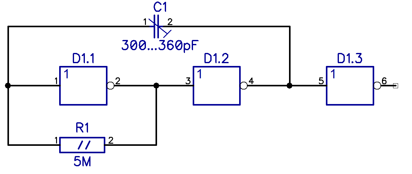
Figure 32: A Simple Logic Generator
Do not forget that to improve the accuracy of the testimony, it is necessary to take into account the current temperature indicators.
6.2 Moisture Sensors with Voltage Output
The electronics industry has already worked for us and has created devices that produce the finished analog signal. An example of such sensors are HIH-4010 sensors from Honeywell, with an accuracy of ± 8%.
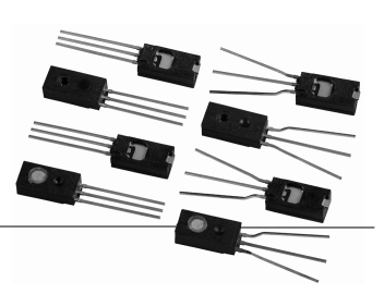
Figure 33: Humidity sensors with voltage output. General view
For such sensors, graphs of output voltage versus humidity are indicated in the data sheet:
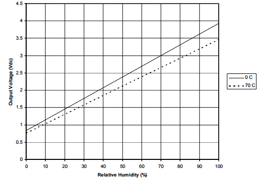
Figure 34: Sensor output voltage versus humidity
With such sensors, a calibration passport is often supplied that contains output values for two different humidity values at a certain temperature. . Sufficiency to specify this data in the program and we get ready calibrated sensor values.
6.3 Humidity sensors with digital output
Our latest sensor in this category will be a digital humidity sensor.
We have already reviewed one of them in the section of temperature sensors - this is SHT1x. However, there are many combined humidity and temperature sensors and, to be honest, I did not come across digital pure humidity sensors, which, incidentally, is not surprising - one without the other anywhere.
We continue our discussion regarding the calculation of humidity from the SHT1x sensor. Derived from this sensor must be converted. In the datasheet are the necessary formulas:
 (12)
(12)And the polynomial coefficients:
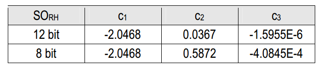
Figure 35: Polynomial coefficients for the V4 version
It should be noted that the relative humidity depends on the temperature and requires an adjustment using the following formula:
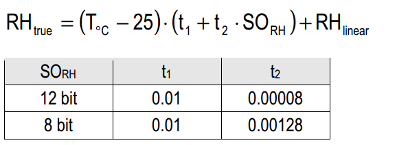
Figure 36: The relative humidity correction depending on the temperature
7 pressure sensors
A pressure sensor is a sensor that records the pressure of the medium being measured, which can be air, gas or liquid.
Depending on the task, it may be necessary to measure both absolute pressure, pressure relative to atmospheric pressure, and differential pressure — that is, the pressure difference between two measurement points.

Figure 37: Pressure.
In the technical characteristics of the sensors can be specified different units of measurement:
- millimeters of mercury - mm Hg;
- Pascal - Pa, Pa;
- Pound-force per square. inch - Psi
- Bar - bar
- Physical atmosphere - ATM
To assess the working range of the sensor, remember that 1 atm is approximately 1 bar or 100 kPa; similar to 760 mm Hg and 15psi. The second after kPa in the sensors is psi, so just remember that 100psi is about 7 atm.
Wikipedia has a wonderful table with exact conversion factors from one unit of measurement to another: https://ru.wikipedia.org/wiki/Use of
pressure_measurement_ pressure sensor is a sensitive element placed between two cameras - in one there is a measured pressure, in the other - reference. In absolute sensors, the impact on the crystal is only from one side. Consider the cut-away MPX2100 sensor diagram from Freescale:
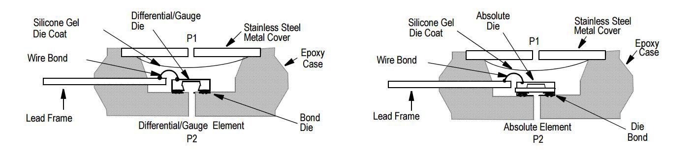
Figure 38: The design of the relative and absolute pressure sensor
The figure shows a sensitive element that changes its properties under the pressure difference. There are several types of sensitive elements. One of the most common - strain gauge - the change in the resistance of the material under the influence of deformation. Often a monocrystal of silicon is taken as the material of such a sensor. One of the problems is the dependence of the sensor resistance on temperature, but, as a rule, thermal compensation is present in all sensors.
Another sensitive element under pressure changes its capacity. In the section of humidity sensors, we have already discussed that this method is problematic for subsequent measurements, and pressure sensors with capacitive output have never been caught by me.
There is also a piezoelectric effect, where the sensing element generates a voltage under the influence of a certain pressure. By the way, I have one such - it is installed in the charging station ZD-6 of a set of individual dosimeters ID-1. The charger contains 4 parallel-connected piezoelectric elements and a mechanical amplifier that presses on the piezoelectric elements; pressure is created by a rotating knob. It is used to generate a voltage of 180-250V for charging the dosimeter.
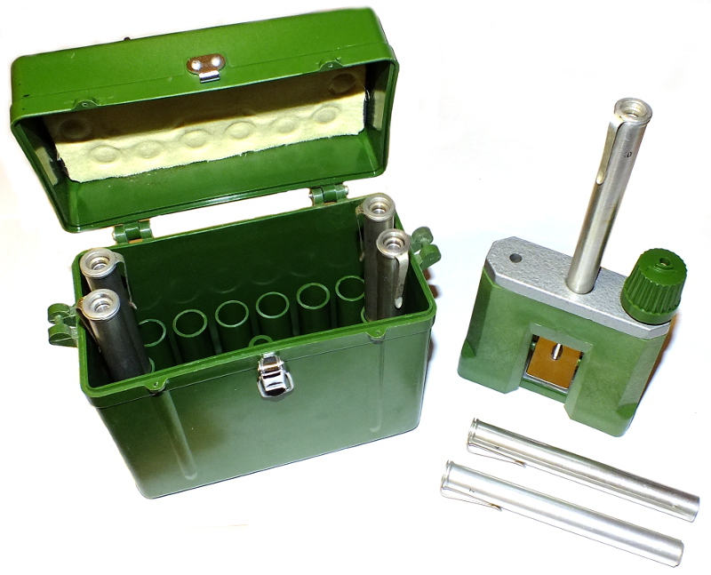
Figure 39: Dose meter ID-1
There are sensors of other types - inductive, resonant and others, but they are found in very industrial facilities and we will not consider them in this article.
7.1 Analog Pressure Sensors
At the output of analog pressure sensors there is a level of current or voltage that must be fed to the measuring path of our device.
Let's make a small lyrical digression and mention sensors with industrial analog signal levels of 0-10V and 4-20mA, intended for connection to industrial automation. Harsh industrial sensors can be seen immediately:
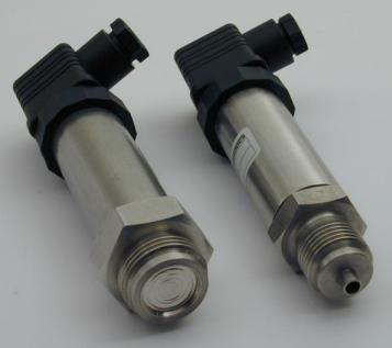
Figure 40: Harsh industrial pressure sensors
However, their wiring is similar to everything described in section 3:
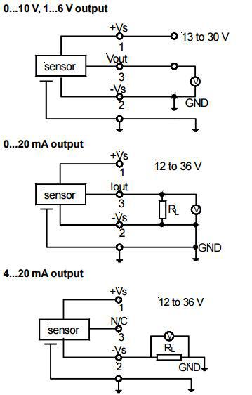
Figure 41: Connecting an industrial sensor
By installing a voltage divider, or selecting a shunt resistance so that the output signal level matches the input ADC range, these sensors can be connected to conventional microcontrollers.
With pressure sensors built according to the bridge balance scheme, there is often the same problem as with thermocouples - many sensors provide only about 40mV for their entire range. For example, this is how the output voltage depends on the pressure for the MPX2100 sensor:
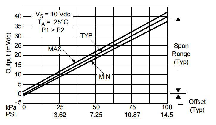
Figure 42: Dependence of the output voltage of the sensor on pressure
So we arm ourselves with a differential low-noise ADC and forwards.
On the other hand, there are more convenient, but more expensive sensors that have a 0-5V, or 0-3.3V output signal and the like, depending on the supply voltage.
These sensors include 40PC from Honeywell:
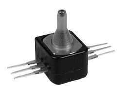
Figure 43: 40PC sensor from Honeywell
Any microcontroller ADC can digitize the output signal of such a sensor. That's just with its accuracy of 0.2% of its value on the market - about $ 40-50.
7.2 Digital pressure sensors
Digital pressure sensor allows you to receive all the data in a more technological way. Its essence is the same - a piezoresistive bridge, differential ADC and interface.
This is what the inside of the MEMS sensor LPS331 from ST in a 3x3x1mm package looks like:

Figure 44: Block diagram of the pressure sensor LPS331
All digital pressure sensors have an integrated temperature sensor and, accordingly, thermal compensation. The sensitivity of this particular pressure sensor is ± 200Pa. Of course, the temperature from this sensor is also available, with an accuracy of ± 2 degrees.
One of the applications of the pressure sensor is barometric altimetry - that is, the determination of relative altitude. As you know, as the height changes, the air pressure decreases. So we will set a zero height on the ground and by rising up, or going down you can determine the distance traveled.
The dependence of air pressure on height is as follows:
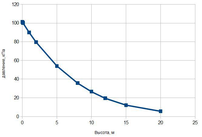
Figure 45: dependence of air pressure on height
To play, I can recommend the EZ430 ‑ Chronos clock-debug kit from Texas instruments based on the CC430F6137 controller. On Habré there is a description of this clock.
They are embedded in a digital pressure sensor Bosh BMP085 worth $ 4. It has a working range of 30-110 kPa and dimensions 5x5x1.2mm.
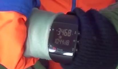
Figure 46: In a few minutes they will show 4500. Meters.
8 Gas Presence Sensors
The sensors previously described make it possible to measure what we can sense on our own. But there may be something else in the air that can kill us completely unnoticed.
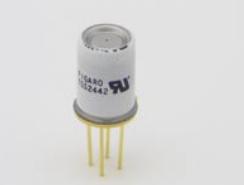
Figure 47: Gas Presence Sensor
This is gas. CO2, CO, methane, propane, ammonia, hydrogen, ethanol, refrigerants and other gases. Most of which are difficult to detect, but which will lead to serious consequences.
A sensor of a certain type is designed, as a rule, only for one specific gas, so if you want to control different gases, then you need to use several sensors.
Various FIGARO sensors are most common, so we will look at them using the example of the TGS2442 carbon monoxide sensor. The sensitive element of such sensors is tin oxide (SnO2). The sensor has a multilayer structure.
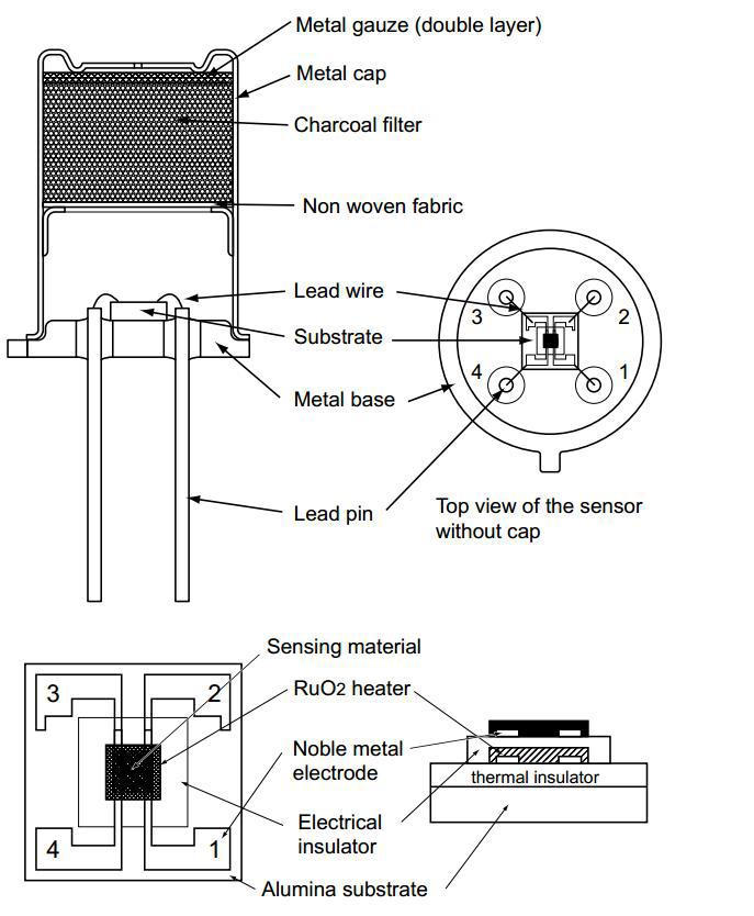
Figure 48: Gas Sensor Structure
First comes a selective filter that passes the target gas and reduces the influence of other gases. After there is a camera with a sensitive element about four contacts. Two contacts are for the heater and two more for the resistor, the resistance of which depends on the gas concentration.
The sensor is connected as follows:
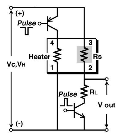
Figure 49: Gas sensor connection
The accuracy of determining the concentration directly depends on the accuracy of the heating time and the time of the signal removal. Both circuits are connected to the power supply for a short time to prevent overheating of the sensitive material.
The heater is supplied with a voltage of 4.8V every second, with a duration of 14 ms. Average heater current 200mA. 5ms before the heater is turned on for 5ms, the meter circuit is turned on and the resistance is measured.
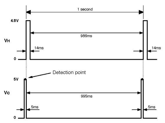
Figure 50: Gas sensor operation cycle The
total gas concentration is determined depending on the ratio of the measured resistance to the resistance at a gas concentration of 100 propromille. The dependence is clearly seen in the following graph:
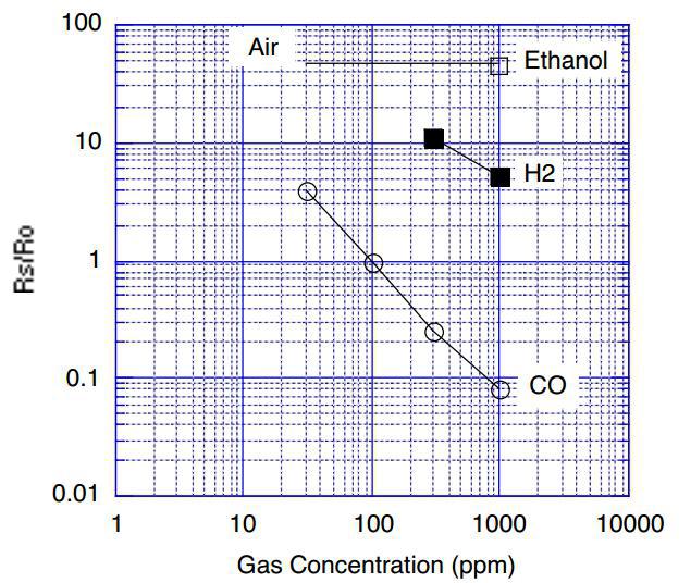
Figure 51: Gas sensitivity. Ro = Rs at 100 ppm CO
PS
This part has turned out more reference than practical, but I hope that this material will help in choosing the type of sensors for your future climate control system.
In the final part of the cycle about the sensors, I will talk about current and voltage sensors, the knowledge of which we will apply when creating a homemade electricity metering device and calculating energy parameters. I decided to split and bring up the issues of frequency, reactive and active power, power factor and harmonic distortion in a separate cycle.
Source: https://habr.com/ru/post/259203/
All Articles