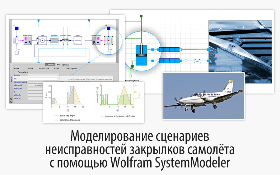
Simulation of aircraft flap fault scenarios using Wolfram SystemModeler
Translation of the post Anneli Mossberg and Olle Isaksson " Modeling Aircraft Flap System Failure Scenarios with SystemModeler ".
I express my deep gratitude to Kirill Guzenko for his help in translating.
Have you heard of the Boeing 747 Dreamlifter, which flew to the wrong airport and was forced to land on a too short runway? Fortunately, this story had a happy ending, and none of the passengers was hurt. Nevertheless, this is a very dangerous situation - when the actual landing distance (hereinafter - FFD) is longer than the runway, and it can occur not only because of an error of the pilot who has gone astray.
One of the possible reasons for this scenario is a flap failure. Flaps are articulated devices located on the rear edges of the wings, their angular position is adjusted to change the lifting properties of the aircraft. For example, a certain flap position may allow an airplane to fly at a slower speed when climbing, or land at a steeper angle without increasing speed. One of their main advantages is that the FPD becomes shorter. This is what puzzles me: Can a slight flap fault increase the FPD so much that the runway will be too short?
To answer this question, one should understand how faults in individual components affect the system as a whole. How will the control system react to this? How to detect this during the test? Is there some kind of safe procedure to compensate for this, and what happens if the pilot or maintenance staff for some reason fails to follow this procedure?
')

Together with my colleague, engineer Olle Isaksson, we decided to use Wolfram SystemModeler 4 and the recently released Wolfram Hydraulic Library to simulate and analyze possible problems that may occur with the flaps of the Cessna 441 Conquest II.

The optimal angular position of the flaps on this model Cessna is set by the pilot manually through the dashboard of the aircraft. In addition to some other factors, the optimal flap angle depends on which phase of the flight the aircraft is in, and the flight phase in turn determines which flight characteristics will be optimal. For example, during takeoff, flaps are deflected by 10 degrees to provide additional lift, and during landing they are deflected by 30 degrees to increase both lifting and braking forces. These seemingly small adjustments of the flaps allow you to land on shorter runways, reduce the force exerted on the aircraft, give the pilot more time to react. For this particular aircraft, there are two additional positions: 0 degrees for the main part of the flight and 20 degrees when approaching landing. Watch the video below to get an idea of how the flaps move.
The flaps on the Cessna are controlled by an electronic system, and are driven by a hydraulic system. That is, the flaps are controlled by electric signals, and the change in their position is provided by a hydraulic system, which includes pumps, valves, cylinders and other necessary components. The pilot controls the flap position through the flap position switch, which is located on the dashboard. When the switch position is changed, an electrical signal is sent, which, together with the limit switches, feeds the flow valve, causing pressure in the hydraulic system to increase.

Together with the supply to the throughput valve, the solenoid controlling the flaps of the valve receives a charge, as a result of which the connection between the cylinder (flap drive), the pump and the reservoir is opened. The hydraulic cylinder is mechanically connected to the flaps, that is, the movement of the cylinder causes a change in the position of the flap, and the movement of the cylinder is due to the change in pressure in the chambers.

Model
The Cessna flap system model that we presented in SystemModeler consists of six customizable components: a pilot, an electrical system, a power plant, a hydraulic system, flaps, and a chassis.

As shown above, the Cessna model is hierarchical, with several sublevels. The pilot receives signals from both the electrical subsystem and the flaps. For example, in the form of data on pressure in the system and information on the current position of the flaps. The power supply subsystem consists of two engines, which are connected to the pumps of the hydraulic system, which, in turn, supply the working fluid under pressure to the flaps and chassis subsystems. In order not to stretch the post to the size of "War and Peace", I will have to omit some of the details in the model description, but they will be given in a subsequent post in which the modeling process will be described in more detail.

Now, when the model components and their interactions were described in a general way, it is time to talk about some potential faults. Despite my fear of flying, I did investigate some reports of unfortunate accidents with Cessna planes. It follows from them that malfunctioning switches, leaks in the hydraulic system and mechanical damage are examples of flap failures that affect all aircraft systems. Thus, let's include the following scenarios in the fault analysis:
1. Pipe leaks in the flaps subsystem.
2. Breakage of the mechanical rod connecting the flap with the cylinder.
3. An electrical fault in the control flap during flight.
Consider the scenario first, when everything works as it should, and the pilot can safely control the flaps. The pilot moves the switch, bringing it to the positions 10 ° -> 20 ° -> 30 ° -> 0 °, which correspond to the take - off -> landing approach -> landing -> flight . It is worth noting that this is a rather strange combination of flap commands, which in real life is unlikely to ever be implemented in 20 seconds; it has only an educational purpose. It, for example, can be considered as a test for the correct operation of the flaps.
First, download WSMLink and set the model.

My colleague Olle systematized the types of problems in the various components of the Cessna model. And in order to investigate, for example, the closure of the contacts on the solenoid, I will need to simply switch to the closure of the solenoid, and then run the simulation.

For the nominal case, all the parameters of the malfunctions are equated to zero, that is, all the components work normally. Since fault modes are structural parameters, WSMSetValues should be used instead of WSMParameterValues .

In what position will the flaps actually be compared to what position the pilot has set in the nominal case?

As you can see, the position of the flaps varies depending on the pilot's commands, but the position changes with a certain delay caused by a certain time of retracting / pulling the flap.
Let's also consider how the pressure is created in the discharge valve, which corresponds to the pressure that is applied to the flaps. Another interesting aspect, especially for electrical faults, is the electrical signal that tells the flaps to open.

In the graphs above, you can see how the pressure peaks correspond to the position of the flaps, and how the peaks of the electrical signals correspond to the commands for changing their position that the pilot sends.
Now let's consider other options and see how they compare with the nominal.
Scenario: Pipe Leaks
In this scenario, the flaps have the same initial position as in the nominal case, but the pipe has a leak in the flap subsystem. Leakage can be embedded in the model by changing the fm parameter for the pipe in the range from 0 to 2.

The images show the model of the system with the current pipe - the flap angle controlled at the left and the actual flap angle, on the right, the pressure change in the discharge hydraulic valve in the hydraulicPower hydraulic subsystem.
We can see that the leakage reduces the pressure in the system, which in turn reduces the pressure force of the cylinder. The reduction leads to a slower flap movement, which increases the response time for the whole system. Such a scenario can be dangerous if the pilot is in a position where the flaps must quickly change their position, for example, if the plane approaches the runway too quickly or at the wrong angle.
Scenario: Broken rod
As previously mentioned, the flap subsystem contains a hydraulic cylinder that controls the movement of the flaps. Let's investigate what happens if a rod connected to the flaps breaks, that is, no force can be transmitted through this rod.

In the two lower plots we can see that the system is under increasing pressure, and the behavior of the electrical signal is as expected. Despite this, the flaps remain in working position. Since the rod is broken, the cylinder cannot transfer any forces to change the position of the flap (see upper right chart) no matter what commands are received. In this case, a seemingly small malfunction will lead to a significantly longer FPD.
Scenario: Electronic system malfunction during flight.
Sometimes it becomes possible to detect a malfunction only when the plane is already in the air, and it is very important to foresee such situations and have some algorithm of actions that would allow to correct any malfunctions. Let's look at the scenario when there are problems in the electronic system during the flight. The pilot was unable to test the flaps before takeoff, that is, the command to retract the flap was first sent already during the flight. An electrical fault in the flap control valve is due to the closure of the solenoid contacts. A short-circuited solenoid opens the circuit during flight, causing the pilot to lose control over the flaps.

The pilot will not notice this fault until he has to change the position of the flap from 10 degrees to zero, while it can still be pulled out of the flaps. However, at the moment when the pilot tries to pull out the flaps, the short circuit will spread to the circuit breaker, and all control over the flaps will be lost, resulting in the aircraft needing a longer runway for landing. So-so perspective, right? However, we could test some algorithm of actions that would help correct the situation.
Scenario: Electronic malfunction during flight and troubleshooting procedure
You can use the Cessna model to implement the troubleshooting procedure, which allows you to safely land the plane, despite the malfunction of the electronic system. This procedure, for example, could consist of moving the switch for a landing and then resetting the circuit breaker. After a reset, it would be possible to directly transfer the flaps to the landing position and safely land, even if the flap retracting is still not working. Let's see if it works.

On the image you can see the simulation of the failure of the electronic system during the flight, when a short-circuited solenoid activates the flaps alarm system.
A short-circuited solenoid opens the circuit during flight, causing the pilot to lose control over the flaps. Then the pilot puts the switch in position for landing, resets the automatic switch and successfully opens the flaps.
What is the conclusion?
Let us return to my question: Can a slight flaw fault increase the FPD so much that the runway will be too short?
Judging by the analysis of failures, this is probably a plausible scenario. This can occur if an increase in the FPD caused by a flap failure (for example, a fault in the electronic system during the flight, which was specified above), exceeds the length of the runway. It should be noted that this model was developed without cooperation with Cessna, that is, some assumptions were made about the device, for example, the electronic system and the values of some parameters. In other words, it is impossible to guarantee that all aspects of the model are 100% accurate or complete. However, it shows the possibility of using simulation as a means of investigating various problem scenarios, how they can be detected, and how to develop procedures for elimination.
I used Wolfram SystemModeler to analyze problems after some sequence of commands, that is, what could have been done during the tests, for example. Using the same principles, SystemModeler can be used to analyze code hard-to-diagnose systems for failures. I also tested the proposed troubleshooting procedure and checked how it all interacts in the system as a whole, what reactions the system has. Such tests allow a better understanding of the principles of human-machine interaction.
If you want to model any faults yourself or just get an idea of the tools I worked with in this post, you can download trial versions of both SystemModeler and Mathematica . Yes, both the Wolfram Hydraulic library and some other libraries can be downloaded from the new Wolfram SystemModeler Library Store .
Source: https://habr.com/ru/post/258817/
All Articles