How to build a smart home
Hello everyone, the Wiren Board team is with you!
We are often asked: “What can be connected to your controller? How to build a “smart home” on it? ”
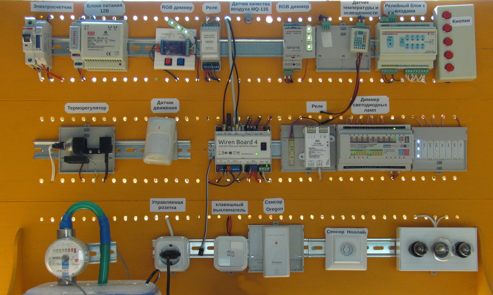
To clarify this issue a bit, we will show the stand where peripheral devices are connected to Wiren Board 4. On his example, we will tell you about typical options for connecting devices and sensors.
')
You can look at the stand through the online broadcast and go to the demo web interface .
A short list of connected equipment:
- counters : water and electricity, pulse and RS-485 / CAN
- Sensors : temperature and humidity, movement, smoke, flame, gas, water leakage
- light control : wired and wireless relays and dimmers
- control of other equipment through relays and digital outputs
Counters
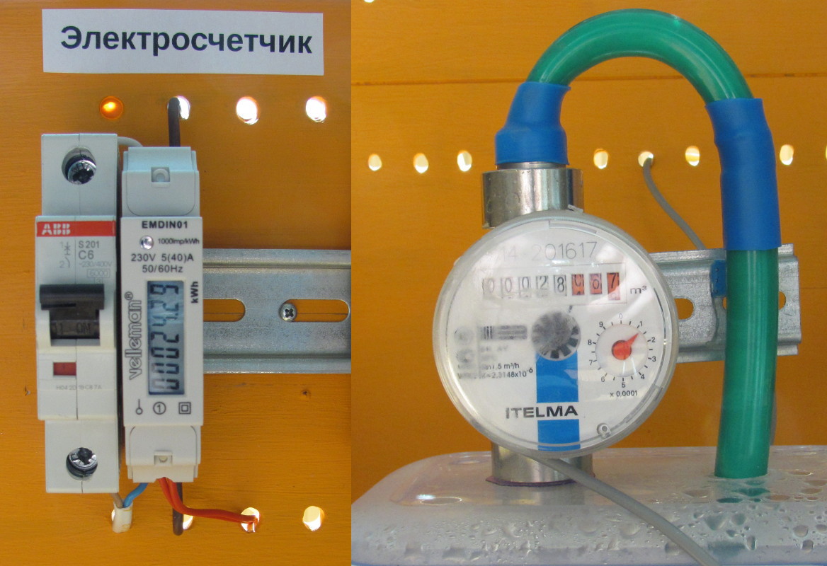
On the stand are installed pulse meters of electricity and water. In addition to them, you can connect the electricity meters “Mercury” via RS-485 and CAN, but they are large, and decided not to install them on the stand.
In impulse counters, the principle of operation is as follows - for every N units (indicated on the device) contact closure occurs. In water meters use reed switches, electric meters - optocouplers.
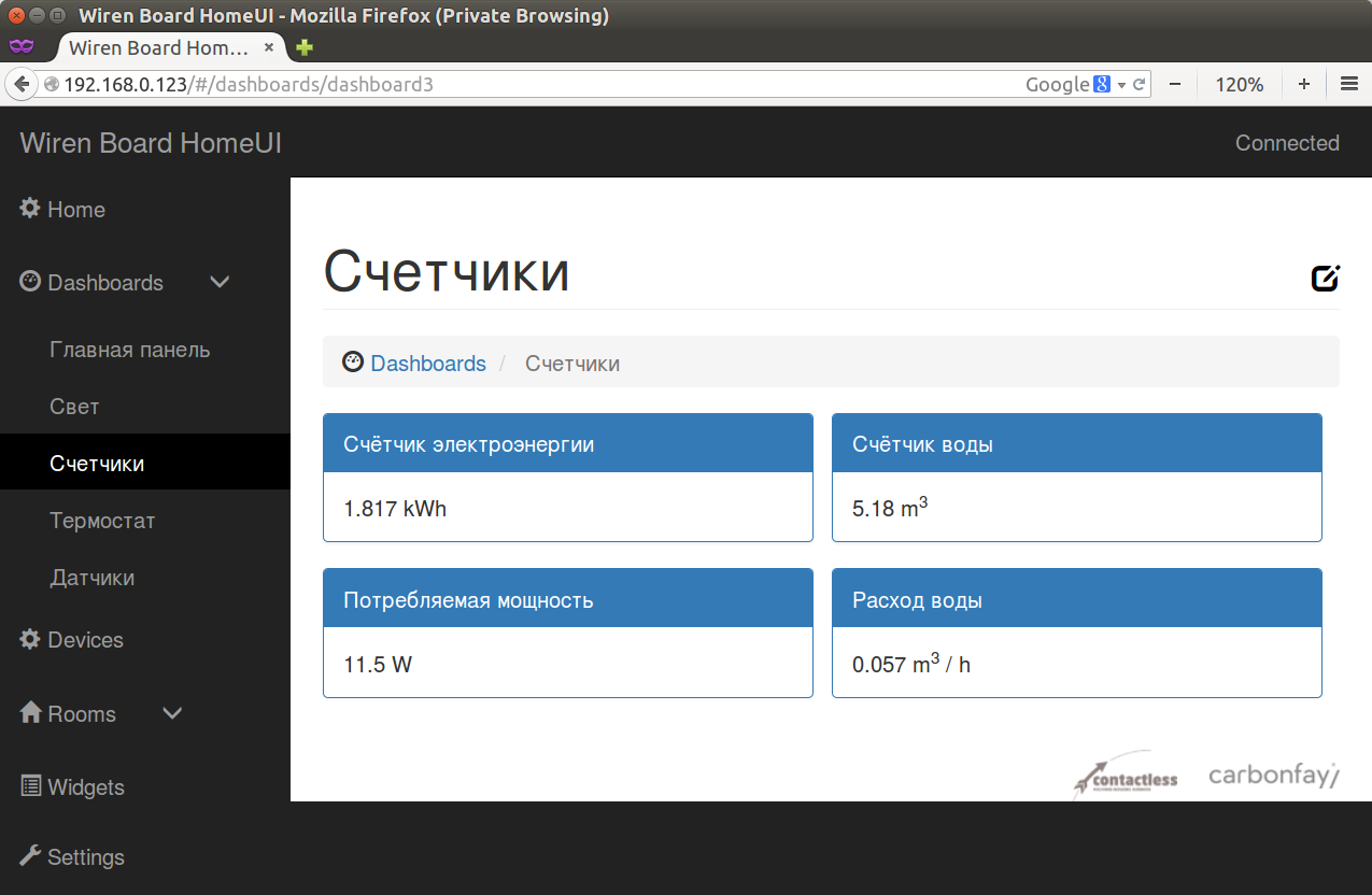
Connect the meter to the inputs of the “dry contact” type. The configuration file indicates the type of counter and constant (pulses per unit). After that, the web interface is displayed as a total amount of readings and their rate of change (power in watts, liters per second, etc.)
Sensors
To collect information, you can connect the following types of sensors:
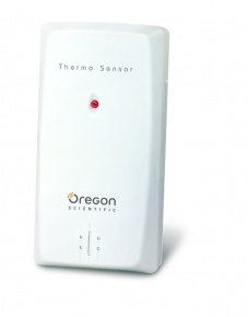
Oregon Scientific Wireless Weather Sensors
They operate at a frequency of 433.92 MHz, they appear automatically in the controller interface - the controller shows all the detected sensors.Among the shortcomings - a small antenna in the transmitter of the sensor, so after a couple of walls it can not be caught. Although on Habré there was an article about how to increase the range.
Temperature and humidity sensors connected via RS-485
and working under the Modbus protocol. They are connected to the common RS-485 bus together with other devices. To appear in the web interface, you need to specify the type and address of the sensor in the configuration file.1-Wire Temperature Sensors
Cheap. When connected immediately appear in the web interface.
Motion Detector
Most of the detectors are made immediately for switching the load of 220V, such it is very difficult to connect to the controller. But there are models with a relay output and 12V power supply - this is exactly what is connected at the stand.Resistive sensors
Resistance 1-50kOhm, before use, calibration with a specific Wiren Board is required. For home applications, there is little point in them. But it can be useful. An MQ-135 air quality sensor and a 10k thermistor are connected at the stand.Smoke, fire, gas, water leakage sensors, etc.
There are a lot of such devices on the market, for convenient connection it is necessary to take with relay outputs, normally closed. Then on one wire you can connect several pieces in series. When a single sensor is triggered, it will break the common circuit, and the signal will go to the controller. At the stand there, but the connection is similar to the motion detector.External buttons
Buttons are not really sensors, but they are also convenient for organizing scenarios. They can be connected either directly to the digital inputs of the controller, or to external modules on Modbus.Light control
Someone says that control of the light is not necessary, others consider it the main function of the “smart home”. Therefore, today we will pay more attention to the light.

LED strip control
LED strips come in two basic types: color-changing (RGB) and single-color. Colored ribbons can be used at home for decorative lighting, and monochrome white and as the main lighting.To turn on the tape, you need to connect it to a voltage source of 12V (or 24V) through a dimmer for tapes. Then, using a dimmer, you can control the color of the RGB tapes and adjust the brightness of the monochrome.
Our booths are equipped with WB-MRGB dimmers of our production and Uniel and “Smart House” dimmers. All of them are connected via RS-485 bus.
In addition to them, a nooLite RGB dimmer is connected via a 433 MHz radio channel. But since the installation of LED strips in itself implies a lot of work on the installation of the tapes themselves, wires, additional power supplies, we would also advise control devices to use wired ones. Then you will get reliable operation with low price of modules, and the 433 MHz radio channel is still not immune from interference.
Dimming lamps 220V
The controller supports Uniel dimmers connected via RS-485. If the lamps just need to be turned on / off, then relay units may be useful (our own ones are supported by ICP-DAS, Smart House, Uniel, etc.).Newbies (such are often found among developers) often think so - here I’ll fill in the control of lights from an iPhone and there will be happiness. The more experienced understand that control needs to be duplicated with wall switches (or a control panel). Of course, going to the toilet with an iPhone is innovative, but the grandmother who came from the village would have to explain for a long time how to use it all.
Solutions to the problem:
- wall control panels - beautiful, comfortable, expensive
- ordinary switch. The signal from it is inserted either directly into the controller, or into a digital input module connected via RS-485. But the relay and dimmer modules of our production have inputs for two external control buttons. This allows the modules to work completely autonomously - pressed the button, the light came on - and at the same time remain controlled from the controller. In general, this increases the reliability of the entire system: if the central controller fails, the RS-485 bus breaks and in other emergency cases, the lighting and wall switches continue to operate normally.
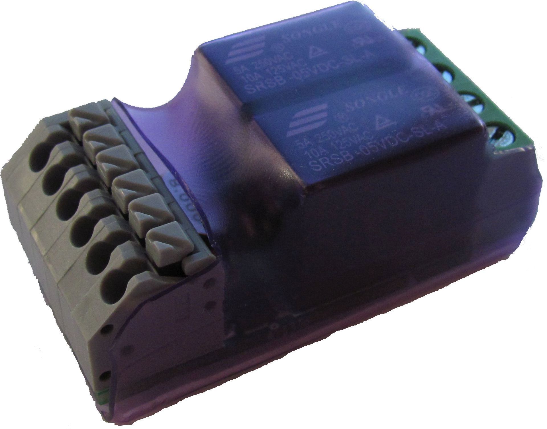
The “classic” installation scheme involves the installation of all control equipment on a DIN rail inside the switchboards. This is convenient, but the payback is tens of meters of wires from each light bulb and switch to the switchboard. But this can be avoided if the control modules are located closer to the lamps and switches - then all the lamps are powered from the common wiring of 220V, and the control devices are connected by one RS-485 bus. For ease of installation according to this scheme, we have developed a compact relay unit with two channels of 5A each; it is placed even in a standard box.
Other load
A powerful power load - pumps, heat guns, groups of sockets - should be switched through contactors. They usually have control coils on 220V (rarely on 12 / 24V), so they will have to use a relay output to control the contactor.

Examples of other devices on the stand:
- a small 12V heater is connected directly to the relay output of the controller
- 12V fan is switched on by the open collector output
- 220V water pump is controlled via an external relay unit via RS-485
The pump is also controlled by a physical button connected to the relay unit.
To simulate a scenario to maintain a certain temperature, a mini installation was assembled from a heater, fan, thermal sensor and a large radiator. At the same time, the details are arranged so that the delay between the sensor readings and the heater operation is manifested.
This situation is often observed in practice - at first the boiler heats the water in the pipes, and only then the heat is transferred to the air. To maintain a constant temperature, a rule for a thermostat is written on the script engine built into Wiren Board.
Conclusion
The complete scheme of our booth, where the connection of all devices is shown, see here .
If you have any questions about the devices from the article or the connection of other devices, we will be happy to answer in the comments. In the same place, we will be happy to hear stories about your experience in building smart homes and other automation.
Source: https://habr.com/ru/post/258677/
All Articles