Smart quest in reality: demons and wiring
Many have heard about quests in reality - escape the room games of the genre transferred to our world. Solve puzzles, get answers, go to the next stage. You need to finish in an hour, as a result, the door opens to the exit. But few know how they are arranged inside. In this article we will look behind the scenes of one of these quests, as well as compare it with others in technical terms.
As a developer of escape rooms, I have seen the implementation of some of them. Usually the quest is divided into unrelated blocks, which together realize the possibility of passing. However, for our quest, we used a centralized architecture. I will try to tell you what the pros and cons of these approaches, and also describe what tasks the "technician" solves, creating quests in reality, because This topic is not well disclosed on the Internet.
')
Logically, the quest scenario is divided into tasks. For example, the customer wants to “enter the code in the keyboard ⇒ a light bulb comes on”. Accordingly, the task for the technician here is to make a keyboard that lights the light bulb when entering the correct password. Arduino immediately comes to mind, which controls the light bulb and keyboard. So usually done.
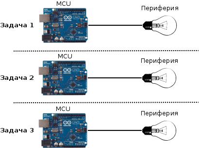
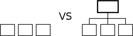
Standard architecture
As a result, we obtain separate, not related to each other tasks, which together are the quest. This approach has a serious disadvantage: lack of flexibility. The need to make changes leads to a long repair, requiring to climb into hard-to-reach places, and even break walls and ceilings in order to gain access to the cherished components. Changes in the quest are caused by:
A simple example: the task is ready. But you want to change the color on a controlled searchlight. To do this, go to the place where the arduin is installed, connect the laptop, look for the code to the task, change it, load it, and then test it. Well, if it works out the first time. In my experience, it is not uncommon for such seemingly elementary changes to lead to serious consequences: if you accidentally hit a wire, the whole task collapses or the component burns. The quest stops at the hysterical team.
Another example. The operator (the person in charge of the quest and accepting players) calls and says that something has broken (for example, after entering the code the light does not light up - symptoms). To fix this, you need to come to the site, connect a laptop and start to understand. After all, it is not known what broke: a light bulb, wires, a controller, or something else. It is necessary to carry out some tests, excluding possibilities. It takes time, especially when the problem “that is, it does not”, i.e. sometimes the light comes on (all is well) and sometimes not.

Nightmare technique
When debugging, you have to stand for hours in uncomfortable positions with a laptop, because Arduin tightly secured together with a bunch of wires that you do not want to touch: everything will break. In the dust, dirt, afraid to move. With operators who periodically come in and ask "well, when already, people are waiting there." At such times, you compare your activities with prostitution and consider the possibilities of corresponding career growth.
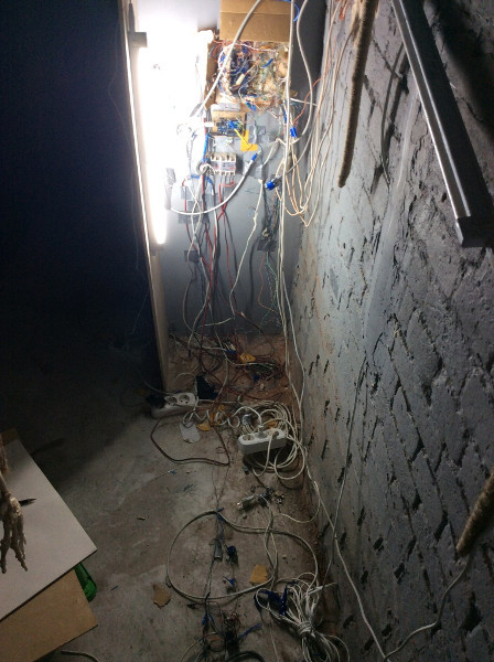
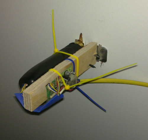
Implementation of one of the tasks in one of the quests. From above in the center of arduin.
The worst situation here is interfering with the breakdown of tasks. For example, the customer wants the keyboard from task 1 to affect the light bulb in task 2. This means that you need to pull the wires from one arduin to another and change the code in both.
So, the lack of flexibility in such quests leads to great difficulties in the creation and maintenance. Problems also appear with the customer, because repair is delayed and waiting for the players for half an hour begin to boil.
How to solve this problem? How to ensure quick access to all devices, as well as the ability to quickly change the connections between different components? It is logical to connect all devices to the network and manage them from one computer .
Each event (in the example above, this button press) will be handled by the central computer, and if the button presses make up the correct password, it will give the command to light a light bulb. If you need to make changes (for example, change the password or make the light on for 3 seconds instead of 5, or even light the lights in another room), you just need to change the code on the computer. Walls do not need to break.
Our quest uses this architecture. I will try to tell in more detail how it is implemented, and what difficulties arose during development.
To begin with the list of peripherals:
All this smoothly scattered on 6 rooms.
I will say right away: the customer was set a goal to collect a questfrom matches and acorns of the lowest cost. Therefore, the components were chosen accordingly (computers with avito, for example). The complicating circumstances did not allow the use of the most appropriate technology. For example, at the hottest moment, the guy who owns the magic of photoresist quit, because of what he had to use boards for prototyping (Arduino). In short, collected as best we could from what was.
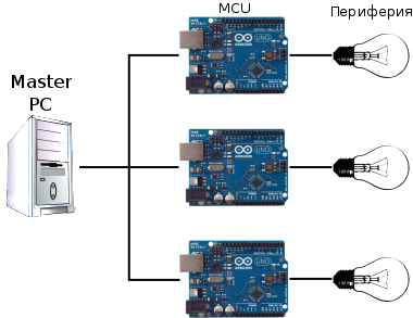
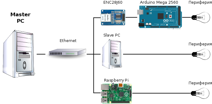
A normal PC with Debian is used as a control device. It runs a demon that controls the entire quest. The network uses Ethernet and UDP. Ethernet is well supported by both computers and peripherals (avr). UDP is easy to implement, and therefore there are good libraries for MCs that support it.
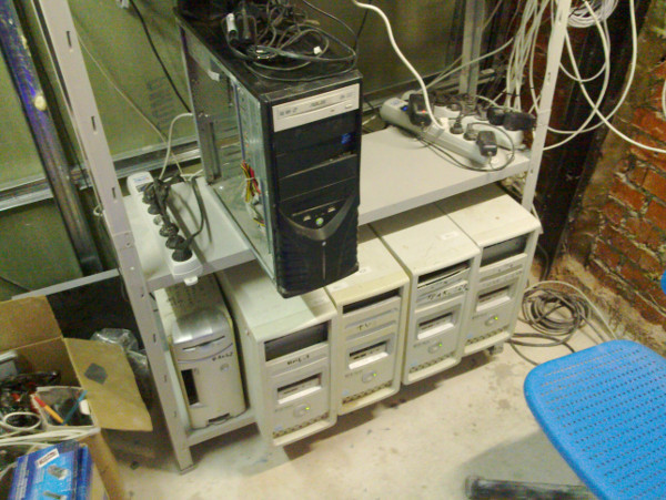
Server Quest. One computer (lower left) controls everything, the rest are needed to display the video.
The variety of peripherals leads to three types of devices that need to be connected to the network. These are Arduino Mega, Raspberry Pi and a regular computer with Debian. The last two do not cause questions, the first is to stay.
C ++ (avr-g ++ compiler) is selected as the programming language, and CMake is used as the build utility. In contrast to the Arduino IDE, this enabled automation of the build process and greater flexibility. For example, you can get access to timers and interrupts that are needed to implement quest tasks, but by default they are occupied with Arduino code.
An inexpensive Microchip ENC28J60 (~ 250r) was chosen as the Ethernet module. EtherCard is used as a library. It refers to arduino-style functions, such as pinMode. Instead of rewriting the library, we took from the Arduino code the implementation of those functions that are needed, thereby obtaining a “mini-version” of the Arduino core. CMake makes it easy to connect a “mini-core” to projects.
The library has many methods, but we need only some of them: send a UDP packet and set Callback to receive a UDP packet. Big data will not walk in our network, so we believe that the data is always placed in one package.
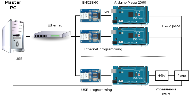
The system would not make sense if you could not change the controller firmware or reboot it remotely. It would be necessary, as before, to break the walls and connect a laptop. We solved this problem using the avr-etherboot project , slightly changing it to work with Mega 2560. It works as follows: .hex files with firmware are stored on a central computer and are accessible via TFTP protocol. Avr-etherboot generates a bootloader that is flashed by an ISP to each controller. It is an ISP, because USB-UART firmware is implemented by the Arduino bootloader, which may already be missing. When the controller starts downloading, the bootloader starts up, connects to the network and downloads the firmware via TFTP (each controller downloads its own, since the bootloaders are slightly different). Next is the work of the firmware on each MK. The written script allows you to generate a bootloader for each MC in the quest and flash it with one command.
But what if there is an error in the firmware, and you need to replace it? How to restart all MK? For this, we use a relay (because there are about 50 of them in the quest, we use 8-channel ones ), through which all arduins, except for one, pass. The latter controls this relay and is flashed via USB from the central computer.
It looks not easy, but once written scripts allow you to reflash all devices with one command, if required.
A funny, but important note: since we use the debug board in production, we need to constantly think about reliability. Not one hour was spent on debugging the code when the problem was in the wire that had fallen off. Therefore, the connection of the periphery with MK, ENC with MK and power made with the help of wires and terminals PLS and BLS. Experience shows that without a crimper it is not always possible to clamp them well, so one option remains - soldering. Most of the failures in the quest, because of which you have to cancel the game - not problems in the code or logic, but trivially fallen off wires.
So, we have a periphery that can perceive the actions of the players or do something themselves. We also have a quest scenario. It should be said that this is not just a sequence of actions: options are possible in it. For example, you can first go through room A, and then room B, and vice versa. There are also tasks that work "independently", for example, you can press a button as many times as you like, after which the notorious light bulb will come on, and this can be done at any time, regardless of the stages completed. How is this easiest to implement?
We will use several processes. Each process will have full access to the periphery. Also, the processes will interact with each other. In separate processes we will carry out independent tasks and expectations of events (for example, the correct password is entered in the keyboard). When an event occurs, the processes will react as needed.
The main scenario is a separate process. He awaits the events of the passage of each of the rooms, and also gives commands to the periphery to perform actions.
All this is implemented in C ++ and standard libraries (unistd.h, sys / *). The interaction between the processes is performed using unnamed pipes. In order to read several processes from a single UDP socket on the periphery, a “branching” pipe is used, according to the number of listening processes. A packet received from a specific device is sent to all these pipes, the listening process already reads from its pipe.
Additionally screwed TCP-server that allows you to manage the quest, creating events and showing the log. It is possible to communicate with peripherals directly through it, which is very useful for debugging, because You do not need to “quench” the quest-daemon to release the port and gain access to the peripherals. TCP-server allows you to create a web interface to the quest, allowing you to control the quest from the tablet.
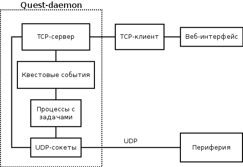
Daemon schema in the context of other components
Example. Let the quest consist of one task: you need to type the code on the keyboard. After that, a light bulb comes on and an exit door opens. In this architecture, it will work as follows:
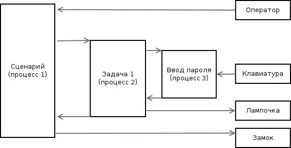
Illustration for example above
For such an example, the complex architecture seems to be something extra, but when there are many tasks, different types of periphery, and the scenario changes both during construction and during the quest, the forces invested in it “pay off” with interest.
Quest web interface
For the convenience of debug all events are recorded in the system log:
If you think about the problem a little more, the following idea will come to mind: you need to separate the low-level (communication with the periphery) and the high-level (quest events) parts of the demon. For example, by TCP. This will make it possible to use a higher level language for translating the script from the customer into the code. It will be easier and faster to write and maintain. The idea came to mind when the quest was already working, so it is not yet implemented.
When the architecture is invented, it remains only to connect peripherals and test tasks. Below is the development process and results:
Video from development:
Total devices:
General remarks:
So, we got a quest that is very easy to change, without doing too much work during construction. We also got handy features, such as web-based management and easy search for errors. Remote support has become possible, since the location has an external IP.
All the breakdowns that occurred since the launch, are due to "iron" problems (the computer died, the wire came off, ...). With the help of the remote control, in a short time, it is possible to determine exactly what has broken. Most can be repaired remotely, telling the operators what to do. Changes to the quest from the customer are also performed "from home".
In comparison, it is obvious that the centralized architecture is good for technically challenging quests, whereas for very simple ones it is suitable for ordinary ones.
If someone needs a code, I will create a public repository. The main one is closed because it contains the script and other secret things.
Thanks for attention!
UPD: Avr-etherboot code for Arduino Mega 2560
As a developer of escape rooms, I have seen the implementation of some of them. Usually the quest is divided into unrelated blocks, which together realize the possibility of passing. However, for our quest, we used a centralized architecture. I will try to tell you what the pros and cons of these approaches, and also describe what tasks the "technician" solves, creating quests in reality, because This topic is not well disclosed on the Internet.
')
Standard approach
Logically, the quest scenario is divided into tasks. For example, the customer wants to “enter the code in the keyboard ⇒ a light bulb comes on”. Accordingly, the task for the technician here is to make a keyboard that lights the light bulb when entering the correct password. Arduino immediately comes to mind, which controls the light bulb and keyboard. So usually done.
Standard architecture
As a result, we obtain separate, not related to each other tasks, which together are the quest. This approach has a serious disadvantage: lack of flexibility. The need to make changes leads to a long repair, requiring to climb into hard-to-reach places, and even break walls and ceilings in order to gain access to the cherished components. Changes in the quest are caused by:
- A change in the script. In the process of construction occurs constantly, after sometimes.
- Breaking down Components are cheap, so this is also not rare
- The requirements of people who also do the quest: builders, decorators, ...
A simple example: the task is ready. But you want to change the color on a controlled searchlight. To do this, go to the place where the arduin is installed, connect the laptop, look for the code to the task, change it, load it, and then test it. Well, if it works out the first time. In my experience, it is not uncommon for such seemingly elementary changes to lead to serious consequences: if you accidentally hit a wire, the whole task collapses or the component burns. The quest stops at the hysterical team.
Another example. The operator (the person in charge of the quest and accepting players) calls and says that something has broken (for example, after entering the code the light does not light up - symptoms). To fix this, you need to come to the site, connect a laptop and start to understand. After all, it is not known what broke: a light bulb, wires, a controller, or something else. It is necessary to carry out some tests, excluding possibilities. It takes time, especially when the problem “that is, it does not”, i.e. sometimes the light comes on (all is well) and sometimes not.
Nightmare technique
When debugging, you have to stand for hours in uncomfortable positions with a laptop, because Arduin tightly secured together with a bunch of wires that you do not want to touch: everything will break. In the dust, dirt, afraid to move. With operators who periodically come in and ask "well, when already, people are waiting there." At such times, you compare your activities with prostitution and consider the possibilities of corresponding career growth.
Implementation of one of the tasks in one of the quests. From above in the center of arduin.
The worst situation here is interfering with the breakdown of tasks. For example, the customer wants the keyboard from task 1 to affect the light bulb in task 2. This means that you need to pull the wires from one arduin to another and change the code in both.
So, the lack of flexibility in such quests leads to great difficulties in the creation and maintenance. Problems also appear with the customer, because repair is delayed and waiting for the players for half an hour begin to boil.
Centralized approach
How to solve this problem? How to ensure quick access to all devices, as well as the ability to quickly change the connections between different components? It is logical to connect all devices to the network and manage them from one computer .
Each event (in the example above, this button press) will be handled by the central computer, and if the button presses make up the correct password, it will give the command to light a light bulb. If you need to make changes (for example, change the password or make the light on for 3 seconds instead of 5, or even light the lights in another room), you just need to change the code on the computer. Walls do not need to break.
Our quest uses this architecture. I will try to tell in more detail how it is implemented, and what difficulties arose during development.
Implementation
To begin with the list of peripherals:
- Control GPIO (light, locks).
- Information from GPIO (buttons, sensors)
- LED RGB spotlights
- Monitors showing video synchronously (video wall) with the ability to change the speed and add text at runtime
- Peephole with image
- IR receiver
- Large keyboard on the wall, the buttons of which you need to touch with your palm
- RFID sensors
- Matrix keyboard
- LED board with text
- Stepper motor for analogue Soviet mechanical watches
All this smoothly scattered on 6 rooms.
I will say right away: the customer was set a goal to collect a quest
A normal PC with Debian is used as a control device. It runs a demon that controls the entire quest. The network uses Ethernet and UDP. Ethernet is well supported by both computers and peripherals (avr). UDP is easy to implement, and therefore there are good libraries for MCs that support it.
Server Quest. One computer (lower left) controls everything, the rest are needed to display the video.
The variety of peripherals leads to three types of devices that need to be connected to the network. These are Arduino Mega, Raspberry Pi and a regular computer with Debian. The last two do not cause questions, the first is to stay.
AVR
C ++ (avr-g ++ compiler) is selected as the programming language, and CMake is used as the build utility. In contrast to the Arduino IDE, this enabled automation of the build process and greater flexibility. For example, you can get access to timers and interrupts that are needed to implement quest tasks, but by default they are occupied with Arduino code.
An inexpensive Microchip ENC28J60 (~ 250r) was chosen as the Ethernet module. EtherCard is used as a library. It refers to arduino-style functions, such as pinMode. Instead of rewriting the library, we took from the Arduino code the implementation of those functions that are needed, thereby obtaining a “mini-version” of the Arduino core. CMake makes it easy to connect a “mini-core” to projects.
The library has many methods, but we need only some of them: send a UDP packet and set Callback to receive a UDP packet. Big data will not walk in our network, so we believe that the data is always placed in one package.
The system would not make sense if you could not change the controller firmware or reboot it remotely. It would be necessary, as before, to break the walls and connect a laptop. We solved this problem using the avr-etherboot project , slightly changing it to work with Mega 2560. It works as follows: .hex files with firmware are stored on a central computer and are accessible via TFTP protocol. Avr-etherboot generates a bootloader that is flashed by an ISP to each controller. It is an ISP, because USB-UART firmware is implemented by the Arduino bootloader, which may already be missing. When the controller starts downloading, the bootloader starts up, connects to the network and downloads the firmware via TFTP (each controller downloads its own, since the bootloaders are slightly different). Next is the work of the firmware on each MK. The written script allows you to generate a bootloader for each MC in the quest and flash it with one command.
But what if there is an error in the firmware, and you need to replace it? How to restart all MK? For this, we use a relay (because there are about 50 of them in the quest, we use 8-channel ones ), through which all arduins, except for one, pass. The latter controls this relay and is flashed via USB from the central computer.
It looks not easy, but once written scripts allow you to reflash all devices with one command, if required.
A funny, but important note: since we use the debug board in production, we need to constantly think about reliability. Not one hour was spent on debugging the code when the problem was in the wire that had fallen off. Therefore, the connection of the periphery with MK, ENC with MK and power made with the help of wires and terminals PLS and BLS. Experience shows that without a crimper it is not always possible to clamp them well, so one option remains - soldering. Most of the failures in the quest, because of which you have to cancel the game - not problems in the code or logic, but trivially fallen off wires.
Central computer
So, we have a periphery that can perceive the actions of the players or do something themselves. We also have a quest scenario. It should be said that this is not just a sequence of actions: options are possible in it. For example, you can first go through room A, and then room B, and vice versa. There are also tasks that work "independently", for example, you can press a button as many times as you like, after which the notorious light bulb will come on, and this can be done at any time, regardless of the stages completed. How is this easiest to implement?
We will use several processes. Each process will have full access to the periphery. Also, the processes will interact with each other. In separate processes we will carry out independent tasks and expectations of events (for example, the correct password is entered in the keyboard). When an event occurs, the processes will react as needed.
The main scenario is a separate process. He awaits the events of the passage of each of the rooms, and also gives commands to the periphery to perform actions.
All this is implemented in C ++ and standard libraries (unistd.h, sys / *). The interaction between the processes is performed using unnamed pipes. In order to read several processes from a single UDP socket on the periphery, a “branching” pipe is used, according to the number of listening processes. A packet received from a specific device is sent to all these pipes, the listening process already reads from its pipe.
Additionally screwed TCP-server that allows you to manage the quest, creating events and showing the log. It is possible to communicate with peripherals directly through it, which is very useful for debugging, because You do not need to “quench” the quest-daemon to release the port and gain access to the peripherals. TCP-server allows you to create a web interface to the quest, allowing you to control the quest from the tablet.
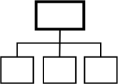
Daemon schema in the context of other components
Example. Let the quest consist of one task: you need to type the code on the keyboard. After that, a light bulb comes on and an exit door opens. In this architecture, it will work as follows:
- Process 1, the script waits for the "run quest" event (blocking call)
- The operator presses the button in the web interface. Chaining it creates a corresponding event, the script continues to work.
- Script starts process 2, “task 1”, waits for the event “task 1 passed”
- Task 1 starts the process 3, “finding the correct password”, waits for the corresponding event from it
- The player enters a password. Each click is processed by process 3. When the correct password is encountered in the input sequence, process 3 generates the event “task 1. The correct password is entered”
- The blocking call in process 2 is completed, process 2 gives the command “light a bulb”. It is passed to the periphery. Process 2 generates the event “task 1 passed”
- The blocking call in process 1 is completed, process 1 gives the command “open the entrance door”. Quest completed
Illustration for example above
For such an example, the complex architecture seems to be something extra, but when there are many tasks, different types of periphery, and the scenario changes both during construction and during the quest, the forces invested in it “pay off” with interest.
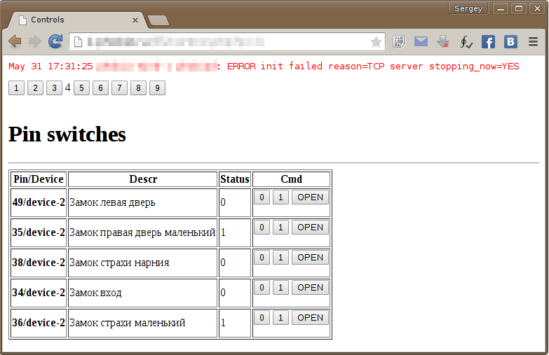
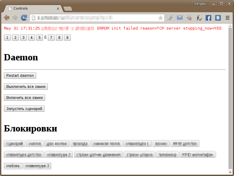
Quest web interface
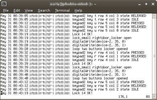
For the convenience of debug all events are recorded in the system log:
If you think about the problem a little more, the following idea will come to mind: you need to separate the low-level (communication with the periphery) and the high-level (quest events) parts of the demon. For example, by TCP. This will make it possible to use a higher level language for translating the script from the customer into the code. It will be easier and faster to write and maintain. The idea came to mind when the quest was already working, so it is not yet implemented.
Tasks
When the architecture is invented, it remains only to connect peripherals and test tasks. Below is the development process and results:
Task solutions and captured jambs
- GPIO. Create a callback that responds to an incoming UDP packet. Depending on the content, it changes the state of the pin, or polls the pin and sends the result. We make out in the form of a library.
- GPIO: electronic locks. Controlled by relay. An important point: it is necessary to add a diode that will take on the current that occurs when it is opened due to a significant induction of the lock. Otherwise, the MK quest will randomly fall when you open the door.
- LED RGB spotlights . Initially controlled from the console via IR. But in the quest it is safer to use the wires, so we will emulate the IR signal using Arduino. The important point: “over the air” a modulated signal is transmitted. By wire from the IR receiver to the searchlight is already normal. Therefore, it is necessary to emulate it. Google, we find a ready-made project . In the code, it remains only to remove the modulation, since We use a wire instead of a pair of IR receiver and IR transmitter. We make out as a library, create a callback that will respond to UDP packets and add it to the device project.
A small feature: on the long wires, the teams reach “through time”. Since the problem is purely electric, and the ransacking guy quits, we had to solve it programmatically, sending each command several times. - Monitors with video. A computer with Debian is great for our purposes. Soft write yourself. This will be a daemon that uses libvlc to display the video. You can change such parameters as volume, playback speed, etc. To display text over video at runtime, we are looking for a program . We do control through UDP. We put in rc.d on each computer (to manage all at once it is convenient to write a script that executes one command to all via ssh). For installation it is convenient to use checkinstall . To implement the ability to change the playback direction for each file, create a second, “reverse” to the original.
- Door peephole with the image. The peephole itself is taken from the viewfinder of an old video camera bought on avito (500r). They used to have CRT monitors. I had to buy two, because the first was inappropriate. The second viewfinder was designed as a separate module with inputs for power and composite video. Google, how to determine which of the wires of the video, power and ground (fee without inscriptions). Connect to Raspberry Pi. We use the same daemon with libvlc as for computers. Warning: in order to use the hardware acceleration on the RPI, you need to compile libvlc yourself .
- IR receiver. We are looking for a remote and receiver with the appropriate modulation frequencies. We connect to Raspberry , configure LIRC with our remote control. We write a daemon that will send received commands to the central computer via UDP.
- Network in Raspberry. For some reason, the network configured via / etc / network / interfaces falls off periodically. Use Network Manager.
- Large keyboard on the wall. We buy thin plates of iron, solder the wires. We connect to the Arduino the resulting capacitive sensors. We are writing a CapSense- based UDP library . We remove all unnecessary, because a lot of buttons, but not very memory.
- RFID sensors. Bought two types: matrix-2 and cp-z. Do not forget to tighten the signal wire. We are writing a OneWire based UDP library .
- Matrix keyboards. Writing a library with UDP support based on Keypad
- LED text display NoName. It is stitched from the computer, it can show 10 different inscriptions. Need to be able to switch them on command. We disassemble, remove the battery, power it from an external source, output the wires from the button for switching the label to the outside, connect it to the GPIO
- Stepper motor for analogue Soviet mechanical watches (we are looking for watches on avito.ru). We connect the driver for the engine L293D . We are writing our SD management library with UDP support. We use timers, we consider that the dial is round, there is a minute and an hour hand. We consider that the motor shaft is connected with the arrows through the gears. In order not to suffer from timing, time will go on the clock, and the central computer will request it. If you do the opposite, the arrows will go unevenly, with jerks due to delays in the transfer of data.
We are looking for a gear with the necessary parameters (to keep on the shaft of the SD, and to go to the gear in hours). We read about the parameters of the gears on Wikipedia . The engine is fixed to the clock with the help of plywood and the builder, who also creates a quest.
Note: in order to find out the gear module in hours, we count the number of teeth, measure the diameter with a ruler.
Note: on sites with gears search does not work well enough. We are looking for ourselves and do not give up. I found a suitable one in a radio-controlled helicopter shop only after 4 hours of unsuccessful search. - Nutrition. Two types of sources are used to power all the elements: a computer power supply unit (5V: Arduino and others) and a power supply unit that comes with LED tape (12V: locks, LED tapes, etc.)
- Old TV (Ruby / Record / ...) with an arbitrary video (not included in the quest) . We connect the Raspberry PI to the antenna input through the RF modulator. The modulator is included with the Sega Mega Drive game console. We are looking for on avito.ru
Video from development:
Total devices:
- 6 x PC
- 2 x Raspberry Pi
- 5 x Arduino Mega + ENC28J60
- 40 relays
General remarks:
Interesting too
- Blocks with components must be well secured, no resistors dangling on the wires. Soldering boards are well suited for this purpose.
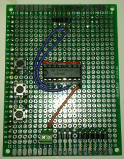
Fee for driver SD - It is convenient to solder the terminal blocks to such boards, and to them to connect wires.
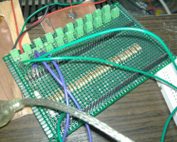
Large keyboard board - Wires are conveniently connected by WAGO terminals. Twisting is unreliable (especially for brittle wires), and soldering is long and inflexible.
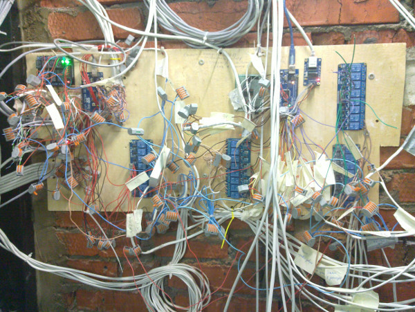
Wall with components. It does not look very good, but there is documentation. - Screeds, hotmelt and shrinking - everything is ours.
Viewfinder in the peephole
Conclusion
So, we got a quest that is very easy to change, without doing too much work during construction. We also got handy features, such as web-based management and easy search for errors. Remote support has become possible, since the location has an external IP.
All the breakdowns that occurred since the launch, are due to "iron" problems (the computer died, the wire came off, ...). With the help of the remote control, in a short time, it is possible to determine exactly what has broken. Most can be repaired remotely, telling the operators what to do. Changes to the quest from the customer are also performed "from home".
In comparison, it is obvious that the centralized architecture is good for technically challenging quests, whereas for very simple ones it is suitable for ordinary ones.
If someone needs a code, I will create a public repository. The main one is closed because it contains the script and other secret things.
Thanks for attention!
UPD: Avr-etherboot code for Arduino Mega 2560
Source: https://habr.com/ru/post/258585/
All Articles