Transistor amplifier class A do it yourself
On Habré there were already publications about DIY-tube amplifiers that were very interesting to read. No doubt, they sound wonderful, but for everyday use it is easier to use the device on transistors. Transistors are more convenient because they do not require warming up before work and are more durable. And not everyone dares to start a lamp saga with anode potentials under 400 V, and transformers for a transistor pair of tens of volts are much safer and more easily accessible.
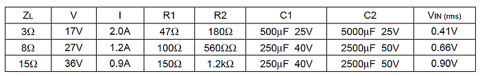
As a circuit for playback, I chose a circuit from John Linsley Hood in 1969, taking the author's parameters per impedance of my 8-ohm speakers.
')
The classic scheme from the British engineer, published almost 50 years ago, is still one of the most reproducible and collects only positive feedback about itself. There are many explanations for this:
- the minimum number of elements simplifies installation. It is also believed that the simpler the design, the better the sound;
- despite the fact that the output transistors are two, they do not need to sort into complementary pairs;
- the output of 10 watts is enough for normal human dwellings, and the input sensitivity of 0.5-1 volts is in very good agreement with the output of most sound cards or players;
- Class A - it is class A in Africa too, if we are talking about good sound. Comparison with other classes will be slightly lower.
Interior design
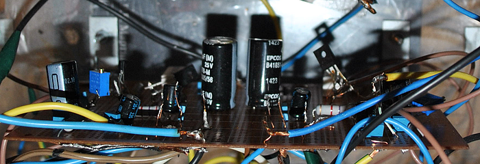
The amplifier starts with power. The separation of the two channels for stereo is most correctly carried out from two different transformers, but I limited myself to one transformer with two secondary windings. After these windings, each channel exists by itself, so you should not forget to multiply by two everything mentioned above. On the breadboard we make bridges on Schottky diodes for a rectifier.
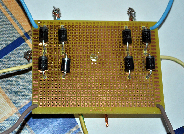
It is possible on conventional diodes or even ready-made bridges, but then they need to be shunted by capacitors, and the voltage drop on them is greater. After the bridges, there are CRC filters from two capacitors of 33000 microfarads each and a 0.75 Ohm resistor between them. If you take less and capacity, and a resistor, the CRC filter will be cheaper and less heated, but the ripple will increase, which is not comme il faut. These parameters, IMHO, are reasonable in terms of price-effect. The resistor in the filter needs a powerful cement, with a quiescent current of up to 2A, it will dissipate 3 watts of heat, so it’s best to take it with a margin of 5-10 watts. The rest of the resistors in the 2W power circuit will be quite enough.
Next, go to the amplifier board itself. In online stores a lot of ready-made whales are sold, however, there are no less complaints about the quality of Chinese components or illiterate layouts on the boards. Therefore, it is better for yourself, under your own “crumbling”. I made both channels on a single layout, then to attach it to the bottom of the case. Run with test items:
Everything except the output transistors Tr1 / Tr2 is located on the board itself. Output transistors are mounted on radiators, more on that below. To the author's scheme from the original article you need to make the following remarks:
- not everything needs to be soldered tightly at once. Resistors R1, R2 and R6 is better to first trim, after all the adjustments to evaporate, measure their resistance and solder the final fixed resistors with similar resistance. Setup is reduced to the following operations. First, with the help of R6, it is set so that the voltage between X and zero is exactly half of the voltage + V and zero. In one of the channels I did not have 100 kOhms, so it is better to take these trimmers with a margin. Then with the help of R1 and R2 (keeping their approximate ratio!) The rest current is set - we set the tester to measure direct current and measure this very current at the point of entry of the positive power supply. I had to significantly reduce the resistance of both resistors to obtain the desired quiescent current. The quiescent current of the amplifier in class A is maximum and in fact, in the absence of an input signal, the whole goes into thermal energy. For 8-ohm speakers, this current, as recommended by the author, should be 1.2 A at a voltage of 27 Volts, which means 32.4 watts of heat per channel. Since setting the current can take several minutes, the output transistors should already be on cooling radiators, otherwise they will quickly overheat and die. For they bask in the main.
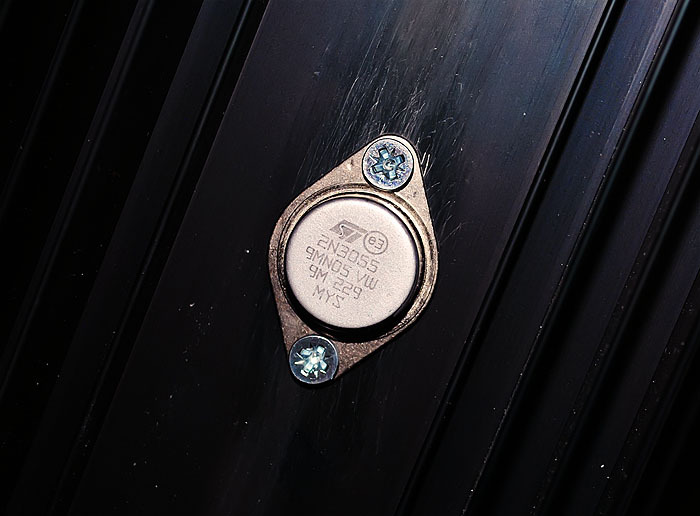
- it is possible that, as an experiment, you would like to compare the sound of different transistors, so you can also leave the possibility of convenient replacement for them. I tried the input 2N3906, KT361 and BC557C, there was a slight difference in favor of the latter. In the pre-test days, KT630, BD139 and KT801 tried, I stopped at imported ones. Although all of the above transistors are very good, and the difference may be more subjective. At the exit, I put 2N3055 (ST Microelectronics) right away, as many like them.
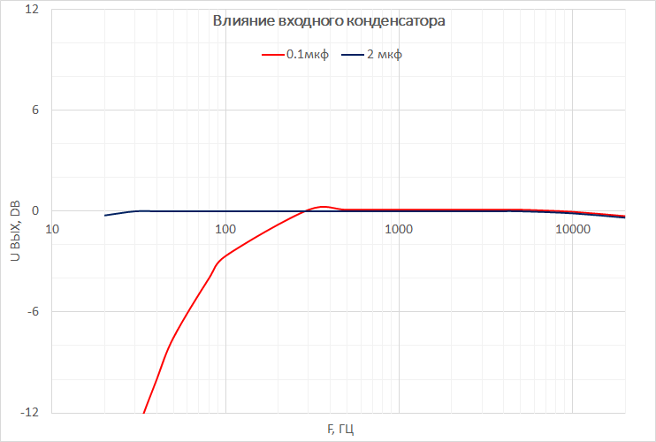
- when adjusting and lowering the resistance of the amplifier, the cut-off frequency of the low frequencies may increase, therefore for the input capacitor it is better to use not 0.5 microfarads, but 1 or even 2 microfarads in a polymer film. A Russian picture-scheme “Class A Ultralinear Amplifier” is still walking around the Network, where this capacitor is generally proposed as 0.1 microfarads, which is fraught with a cut of all bass at 90 Hz:
- they write that this scheme is not prone to self-excitation, but just in case, a Zobel circuit is placed between point X and the ground: R 10 Ohm + C 0.1 μf.
- fuses, they can and should be put both on the transformer and on the power input of the circuit.
- it is very appropriate to use thermal paste for maximum contact between the transistor and the radiator.
Bench and joinery
Now about the traditionally the most difficult part in the DIY - package. The dimensions of the case are set by radiators, and they must be large in class A, we remember 30 watts of heat on each side. At first, I missed this power and made a case with average radiators of 800 cm² per channel. However, when the quiescent current was set at 1.2A, they heated to 100 ° in 5 minutes, and it became clear that something more powerful was needed. That is, you need to either install more radiators or use coolers. I didn’t want to make a quadrocopter, so giant beauties HS 135-250 with an area of 2500 cm² for each transistor were bought. As practice has shown, such a measure turned out to be somewhat redundant, but now the amplifier can be easily touched - the temperature is only 40 ° C, even in the rest mode. Drilling holes in radiators for fasteners and transistors was a problem - the originally purchased Chinese drills for metal were drilled extremely slowly, it would take at least half an hour for each hole. Cobalt drills with an angle of sharpening of 135 ° from a famous German manufacturer came to the rescue - each hole is drilled in a few seconds!
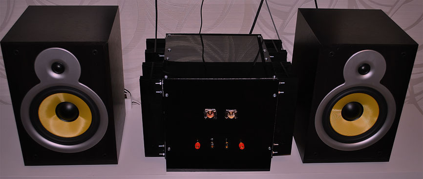
I made the body itself from plexiglass. We order sliced rectangles from glaziers right away, make the necessary holes for fixings in them and paint black paint on the back side.


Colored plexiglass on the back side looks very beautiful. Now it remains only to collect everything and enjoy the muse ... oh yes, during final assembly it is still important to minimize the background to properly dissolve the earth. As it was found decades before us, C3 must be attached to the signal ground, i.e. to the minus of the input-input, and all the other minus can be sent to the "star" near the filter capacitors. If everything is done correctly, then no background can be heard, even if at the maximum volume to bring the ear to the speaker. Another "earthen" feature that is typical for sound cards that are not electrically isolated from the computer is interference from the motherboard, which can crawl through USB and RCA. Judging by the Internet, the problem is often encountered: in the columns you can hear the sounds of the HDD, printer, mouse, and the background of the system unit BP. In this case, the easiest way to break the ground loop, taping the ground to the amplifier plug. There is nothing to fear, because There will be a second ground loop through the computer.
I did not do the volume control on the amplifier, because I did not manage to get some high-quality ALPS, and I did not like the rustling of Chinese potentiometers. Instead, a conventional 47 kΩ resistor was installed between the “ground” and the “signal” of the input. Moreover, the regulator for the external sound card is always at hand, and in each program there is also a slider. Only the turntable does not have a volume control, so to listen to it, I attached an external potentiometer to the connecting cable.
I guess this container in 5 seconds ...
Finally, you can start listening. The sound source is Foobar2000 → ASIO → external Asus Xonar U7. Speakers Microlab Pro3. The main advantage of these speakers is a separate block of their own amplifier on the LM4766 microcircuit, which can be immediately removed somewhere far away. Much more interesting with this acoustics sounded the amplifier from the Panasonic mini system with the proud Hi-Fi inscription or the amplifier of the Soviet player Vega-109. Both of the above apparatus work in class AB. Presented in the article JLH outplayed all the above comrades in one gate, according to the results of a blind test for 3 people. Although the difference was heard with the naked ear and without any tests - the sound is clearly more detailed and transparent. It’s quite easy, for example, to hear the difference between MP3 256kbps and FLAC. I used to think that the effect of lossless is more like a placebo, but now the opinion has changed. Similarly, it became much more pleasant to listen to files uncompressed from loudness war - dynamic range of less than 5 dB is not ice at all. Linsley Hood is worth the time and money, because a similar brand amp will cost much more.
Material costs
Transformer 2200 p.
Output transistors (6 pieces with a margin) 900 p.
Filter capacitors (4 pieces) 2700 r.
Disperse (resistors, small capacitors and transistors, diodes) ~ 2000 p.
1800 radiators
Plexiglas 650 r.
Paint 250 r.
Connectors 600 p.
Boards, wires, silver solder, etc. ~ 1000 p.
TOTAL ~ 12100 p.
Source: https://habr.com/ru/post/258507/
All Articles