We manage AB400S Wireless Switch socket without remote control
Recently, I had 3 sockets AB400S Wireless Switch controlled by radio 433 MHz. The console from them was lost and the owner did not need them. As always, the inspection began with a parsing on the components.
Here, in fact, the kind of viscera of this outlet. The blue wires and the 1.2kΩ resistor were soldered by me, but more on that later.
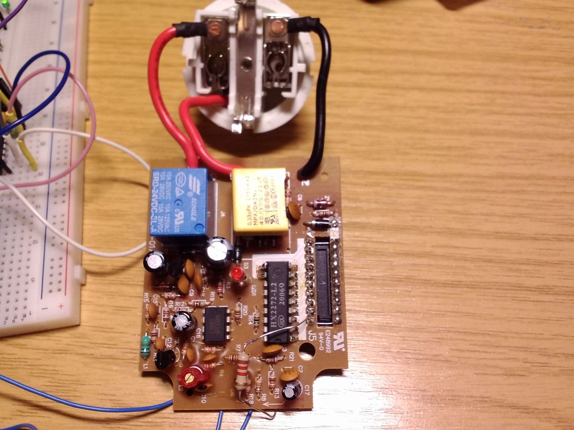
From the top you can immediately see the capacitor power supply and 24V relay, below the signal receiver with a filter at the op-amp and the decoder of the received signal HX2272-L2 itself. To the right of him are the legs from the switch (DIP switch), which is set to the "address" of the outlet.
I set out to connect it with an ATmega8 microcontroller and try to turn on the relay. I'm not a fan of capacitor power supplies, especially when the board will lie on the table in front of the nose. For the power supply, I used the 5V source, from which my microcontroller runs, inserted into the brainboard (on the mock-up board with plug-in contacts).
')
I had a 433 MHz transmitter from another device. In order to exclude the inactivity of the radio channel when testing the program transmitting data to the decoder, I decided to connect the microcontroller to the decoder directly. Solder the wires to the VCC (18), GND (9) and DIN (14) terminals. I soldered them not specifically to the legs of the chip, but just on these lines where it was convenient.
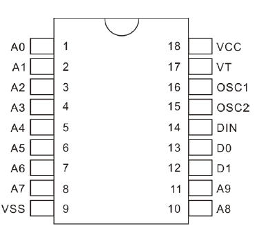
From the description of the chip, it follows that the information transmitted to the decoder consists of one word (word) consisting of 12 bits, followed by a sync bit. Specifically for our decoder, it looks like this:

The value of the bits is set by the voltage level at the inputs A0-A9, bits D0-D1 correspond to the same outputs. If the received address bits match the values set on the switch, then the outputs D0 and D1 accept the values of the received bits D0 and D1. The bit can be 0, 1 or f (floating). In the case of "floating" input is not connected. On the outlet board, you can use 0 and "floating". There is no possibility to set the unit, since there is no pull-up resistor. In the program, I used all three options, so a resistor of 1.2 kOhm was soldered to A0 to check the performance.
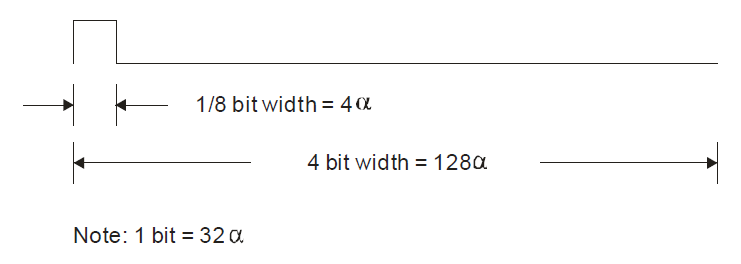
The bits are encoded as follows:
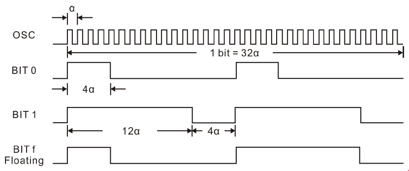
Each bit consists of two pulses. For 1 and 0, the first and second pulses are the same, and “floating” in the first cycle has the sequence “0”, in the second “1”. α is the period of the decoder clock generator. Its value is set by the resistor connected to the legs of OSC1 and OSC2. In our version of the board, it has a value of 1 MΩ.
According to the above graphs, you can determine the frequency at which the decoder operates. The frequency scale is logarithmic and 10 kHz offset. From the figure it follows that the frequency of the clock generator is approximately equal to 35 kHz.

Check the oscilloscope. To do this, we put the oscilloscope probe on the OSC2 foot.
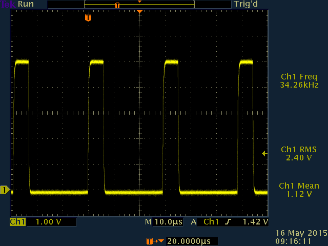
We take a more accurate value. For the decoder, α will be equal to 1 / 34.26 kHz = 29.19 μs. From the description it follows that the decoder operates at a frequency of 2.5 ... 8 times greater than the device that forms the incoming signal on the DIN leg. This means that for encoding the signal α of the transmitter, it can be, for example, 29.19 μs / 4 = 7.3 μs.
About the code I will make a reservation right away that I am not a programmer. If you have any suggestions how to make it better, I will be happy for your advice.
The data to be sent is stored in a vector. Bits A0 ... A9 correspond to the values set on the switch. (Standard combination from the instruction manual) A relay is connected to the D0 output of the decoder through a transistor. The port to which the decoder input is connected is configured for output and is immediately turned on during initialization. When the microcontroller is flashed, the relay should switch on immediately according to the data in the vector.
The transmission cycle of the same data is repeated 3 times. Pressing the button inverts the last bit (on / off function) and resets the number of transmissions (transmitNum). I used a timer that calls a function (rf_function) every 7.3 µs if the button connected to the microcontroller was pressed.
Each time the function is called, the counter α is incremented by one. If the number of passed α corresponds to the required number of cycles for the formation of one or another bit, then the pin value is inverted. After 16α (time of one cycle), the counter α is reset and the cycle counter increases by one. The operation is repeated again. After two cycles, a new bit is taken from the vector and the operation is repeated until 12 bits are transmitted. Then a sync pulse is sent. It has other temporal characteristics.
At the stage of the test with the disassembled socket, it was possible to judge about the program’s performance by the illuminated LED (the indicator of the socket activation), since power was supplied to 5V, and the relay was rated at 24V.
After successful testing and connection of the transmitter (433 MHz), the socket immediately began to be controlled via radio.
The next goal is to connect the microcontroller with a smartphone and control three sockets. But that's another story.
Here, in fact, the kind of viscera of this outlet. The blue wires and the 1.2kΩ resistor were soldered by me, but more on that later.
From the top you can immediately see the capacitor power supply and 24V relay, below the signal receiver with a filter at the op-amp and the decoder of the received signal HX2272-L2 itself. To the right of him are the legs from the switch (DIP switch), which is set to the "address" of the outlet.
I set out to connect it with an ATmega8 microcontroller and try to turn on the relay. I'm not a fan of capacitor power supplies, especially when the board will lie on the table in front of the nose. For the power supply, I used the 5V source, from which my microcontroller runs, inserted into the brainboard (on the mock-up board with plug-in contacts).
')
I had a 433 MHz transmitter from another device. In order to exclude the inactivity of the radio channel when testing the program transmitting data to the decoder, I decided to connect the microcontroller to the decoder directly. Solder the wires to the VCC (18), GND (9) and DIN (14) terminals. I soldered them not specifically to the legs of the chip, but just on these lines where it was convenient.
From the description of the chip, it follows that the information transmitted to the decoder consists of one word (word) consisting of 12 bits, followed by a sync bit. Specifically for our decoder, it looks like this:
The value of the bits is set by the voltage level at the inputs A0-A9, bits D0-D1 correspond to the same outputs. If the received address bits match the values set on the switch, then the outputs D0 and D1 accept the values of the received bits D0 and D1. The bit can be 0, 1 or f (floating). In the case of "floating" input is not connected. On the outlet board, you can use 0 and "floating". There is no possibility to set the unit, since there is no pull-up resistor. In the program, I used all three options, so a resistor of 1.2 kOhm was soldered to A0 to check the performance.
The bits are encoded as follows:
Each bit consists of two pulses. For 1 and 0, the first and second pulses are the same, and “floating” in the first cycle has the sequence “0”, in the second “1”. α is the period of the decoder clock generator. Its value is set by the resistor connected to the legs of OSC1 and OSC2. In our version of the board, it has a value of 1 MΩ.
According to the above graphs, you can determine the frequency at which the decoder operates. The frequency scale is logarithmic and 10 kHz offset. From the figure it follows that the frequency of the clock generator is approximately equal to 35 kHz.
Check the oscilloscope. To do this, we put the oscilloscope probe on the OSC2 foot.
We take a more accurate value. For the decoder, α will be equal to 1 / 34.26 kHz = 29.19 μs. From the description it follows that the decoder operates at a frequency of 2.5 ... 8 times greater than the device that forms the incoming signal on the DIN leg. This means that for encoding the signal α of the transmitter, it can be, for example, 29.19 μs / 4 = 7.3 μs.
About the code I will make a reservation right away that I am not a programmer. If you have any suggestions how to make it better, I will be happy for your advice.
The data to be sent is stored in a vector. Bits A0 ... A9 correspond to the values set on the switch. (Standard combination from the instruction manual) A relay is connected to the D0 output of the decoder through a transistor. The port to which the decoder input is connected is configured for output and is immediately turned on during initialization. When the microcontroller is flashed, the relay should switch on immediately according to the data in the vector.
short sendVector[12] = {0,2,0,2,0,0,2,2,2,2,0,1}; // A0 A1 A2 A3 A4 A5 A6 A7 A8 A9 D1 D0 // BIT0 =0; BIT1 =1; BITf =2 The transmission cycle of the same data is repeated 3 times. Pressing the button inverts the last bit (on / off function) and resets the number of transmissions (transmitNum). I used a timer that calls a function (rf_function) every 7.3 µs if the button connected to the microcontroller was pressed.
rf_function
void rf_function(void) { static short alphaCounter = 0; // static short bitCounter = 0; // static short cycle = 0; // if (bitCounter < 12) // 12 { alphaCounter++; if (cycle == 0) { if ((alphaCounter == 4) && (sendVector[bitCounter] != 1)) // BIT0 BITf { togglePin('C', _PIN0); // } if ( (alphaCounter == 12) && (sendVector[bitCounter] == 1)) { togglePin('C', _PIN0); } } else { if ((alphaCounter == 4) && (sendVector[bitCounter] == 0)) // BIT1 BITf { togglePin('C', _PIN0); // } if ( (alphaCounter == 12) && (sendVector[bitCounter] != 0)) { togglePin('C', _PIN0); } } if (alphaCounter == 16) // { togglePin('C', _PIN0); cycle++; alphaCounter = 0; // } if (cycle == 2) // 2 { cycle = 0; bitCounter++; } } else // { alphaCounter++; if (alphaCounter == 4) { togglePin('C', _PIN0); } if (alphaCounter == 128) { togglePin('C', _PIN0); bitCounter = 0; // alphaCounter = 0; // transmitNum++; // } } } Each time the function is called, the counter α is incremented by one. If the number of passed α corresponds to the required number of cycles for the formation of one or another bit, then the pin value is inverted. After 16α (time of one cycle), the counter α is reset and the cycle counter increases by one. The operation is repeated again. After two cycles, a new bit is taken from the vector and the operation is repeated until 12 bits are transmitted. Then a sync pulse is sent. It has other temporal characteristics.
At the stage of the test with the disassembled socket, it was possible to judge about the program’s performance by the illuminated LED (the indicator of the socket activation), since power was supplied to 5V, and the relay was rated at 24V.
After successful testing and connection of the transmitter (433 MHz), the socket immediately began to be controlled via radio.
The next goal is to connect the microcontroller with a smartphone and control three sockets. But that's another story.
Source: https://habr.com/ru/post/258447/
All Articles