Lamp-rainbow do it yourself
Hi Habr!
The idea of creating a multi-color lamp came to my mind after seeing the fascinating effect of a flashing garland on my six-month-old son. I wanted to create something similar, only performing some useful function - for example, a nightlight, with the possibility of flexible mode setting and with the possibility of remote control. And, of course, the device created should be no less attractive for a child than a Chinese garland.
')
Attention, under the cut a lot of photos.
The choice fell on the creation of a floor lamp-floor lamp, which, due to the dimming of the light by the lamp shade, would not shine like a searchlight at night, would take up little space, and could simultaneously display several colors simultaneously. Something similar was already created by habravchaninin - then it was a lamp showing the weather, collected on Malinka. I did not have the task of climbing the Internet, I just wanted to “flash the LEDs”, so it was decided to take Arduinka as a brain, since a small version of Nano bought from Uncle Liao was lying around at home. For remote control, I decided to use the simplest Bluetooth module Bolutek for a couple of evergreens.
Next came the question of creating the lamp itself. It was decided not to reinvent the wheel, and take ready. A floor lamp with a paper shade, bought in the nearest Ikea, came to the base for quite similar 500 rubles. It was decided that inside it would be possible to fasten several pads on the rod for the LED tape sticker, which would create decent brightness. Tape took color, models 5050, 60 LEDs per meter, without individual control of LEDs.
Sites made of metal mounting tape for fixing underfloor heating - sold in all hardware stores. Reel tape 20m enough for the eyes. From a tape rolled up rings, with a diameter about 14 cm, with a possibility of fixing on a lamp core. At the same time, the rings act as a heat sink, since The tape is very noticeably heated.
Then I began to think about how to independently control the color of all levels, having a limited number of PWM outputs on arduinka. The number of levels chose 8, since with a larger lamp began to bend under the weight of metal pads. Still, the Swedish designers did not expect that something else would be attached to the lamp shaft. Thus, I got the need to control 24 outputs, with the possibility of smooth adjustment of the output voltage to them. Not a single Arduin has so many ways out (it can have Mega, but this solution is primitive), therefore, to solve the problem, I used the ShiftPWM library, which will satisfy any reasonable requirements on the number of levels. With the help of inexpensive and affordable mikruh - shift register 74hc595 and keys uln2803 - provided the required number of controlled outputs and the current required to power the tapes.
First of all, he made 8 pads of metal tape, which he fastened on the rod of the lamp. It was not possible to withstand the same distance between the levels due to the peculiarities of mounting the stock light source, but this turned out to be unprincipled:
Then he prepared the cables of the wires, which led to the levels below. The controller decided to place the bottom of the lamp, closer to the power supply. All the loops, so as not to dangle, tied the tape to the rod:
Next came the turn of the actual assembly circuit. The connection scheme of the shift registers 74hc595 took a sample, from the site-guide to ShiftPWM.
I assembled a scheme on a model board with a single-LED scheme, filled in a sketch example - made sure that everything works as it should:
After that, it's time to build the circuit in production version. Since I wanted to assemble the circuit as quickly as possible, and there was no time to try the LUT-technology - I assembled the controller on two textolite layout boards, 4 by 6 cm in size. On the first one there is an arduin and a bluetooth module for remote control, on the second one are registers, keys, and connectors for connecting tapes:

Then twisted both boards together, it turned out a kind of sandwich:
As a power supply, I took inexpensive Chinese, at 12V, with an output current of up to 5A:
As a case, I used a switch box that fit in:

Next - placed inside the case of the power supply, and a sandwich of the boards, stretching the wires from the tapes inside:
It turned out to be a rather compact device, which was easily hidden under the lamp shade so that it did not attract attention.
To control the controller, I previously wrote a program for Android. In general, any bluetooth terminal will be suitable for controlling the circuit - it will suffice to program a few preset commands to transmit, and to select a custom backlight color, specify the RGB color code in R, G, B format.
Next, I provide the sketch code that should be uploaded. The scheme has 10 preset modes, as well as the ability to set its own colors.
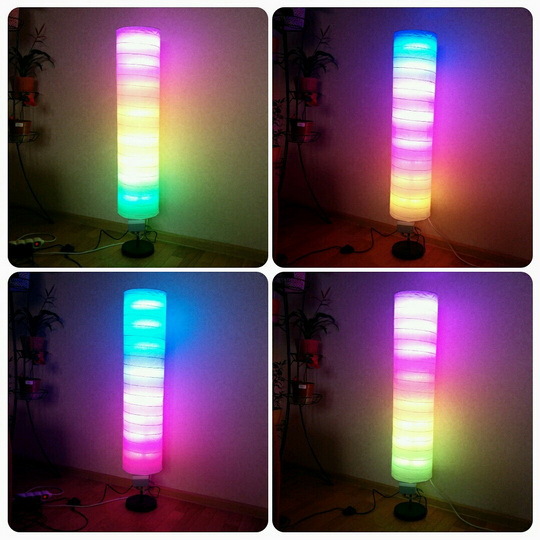
The video shows the rainbow mode, IMHO the most beautiful mode of operation:
And a couple of photos of the finished device - it's a pity that the camera can not convey the richness of color:
The assembled lamp fully satisfies the original idea, looks like a finished product, the wires do not stick out, is controlled easily, the son is satisfied - and this is the main thing!
All components of the controller were purchased on Ebee, everyone can find them there - the prices are minimal. The total cost of the lamp turned out to be approximately: 500r lamp itself, 800r for the LED strip, 100r for the power supply unit, microcircuits for 50r, 200r for the broom, case and steel tape for fastening for 200r. Total - about 1900r.
By the time the assembly took about 2 weeks in free time in the evenings. Surely you can do it faster if you do not get distracted.
What else can you do:
I would be glad to see in comments reviews, criticism, and ideas about improving the design.
Foreword
The idea of creating a multi-color lamp came to my mind after seeing the fascinating effect of a flashing garland on my six-month-old son. I wanted to create something similar, only performing some useful function - for example, a nightlight, with the possibility of flexible mode setting and with the possibility of remote control. And, of course, the device created should be no less attractive for a child than a Chinese garland.
')
Attention, under the cut a lot of photos.
Preliminary Steps
The choice fell on the creation of a floor lamp-floor lamp, which, due to the dimming of the light by the lamp shade, would not shine like a searchlight at night, would take up little space, and could simultaneously display several colors simultaneously. Something similar was already created by habravchaninin - then it was a lamp showing the weather, collected on Malinka. I did not have the task of climbing the Internet, I just wanted to “flash the LEDs”, so it was decided to take Arduinka as a brain, since a small version of Nano bought from Uncle Liao was lying around at home. For remote control, I decided to use the simplest Bluetooth module Bolutek for a couple of evergreens.
Next came the question of creating the lamp itself. It was decided not to reinvent the wheel, and take ready. A floor lamp with a paper shade, bought in the nearest Ikea, came to the base for quite similar 500 rubles. It was decided that inside it would be possible to fasten several pads on the rod for the LED tape sticker, which would create decent brightness. Tape took color, models 5050, 60 LEDs per meter, without individual control of LEDs.
Sites made of metal mounting tape for fixing underfloor heating - sold in all hardware stores. Reel tape 20m enough for the eyes. From a tape rolled up rings, with a diameter about 14 cm, with a possibility of fixing on a lamp core. At the same time, the rings act as a heat sink, since The tape is very noticeably heated.
Then I began to think about how to independently control the color of all levels, having a limited number of PWM outputs on arduinka. The number of levels chose 8, since with a larger lamp began to bend under the weight of metal pads. Still, the Swedish designers did not expect that something else would be attached to the lamp shaft. Thus, I got the need to control 24 outputs, with the possibility of smooth adjustment of the output voltage to them. Not a single Arduin has so many ways out (it can have Mega, but this solution is primitive), therefore, to solve the problem, I used the ShiftPWM library, which will satisfy any reasonable requirements on the number of levels. With the help of inexpensive and affordable mikruh - shift register 74hc595 and keys uln2803 - provided the required number of controlled outputs and the current required to power the tapes.
Embodiment
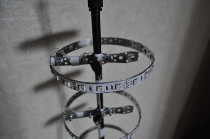
First of all, he made 8 pads of metal tape, which he fastened on the rod of the lamp. It was not possible to withstand the same distance between the levels due to the peculiarities of mounting the stock light source, but this turned out to be unprincipled:
 |  |  |
Then he prepared the cables of the wires, which led to the levels below. The controller decided to place the bottom of the lamp, closer to the power supply. All the loops, so as not to dangle, tied the tape to the rod:
 |  |
Next came the turn of the actual assembly circuit. The connection scheme of the shift registers 74hc595 took a sample, from the site-guide to ShiftPWM.
Wiring register shift registers
Connection diagram uln2803
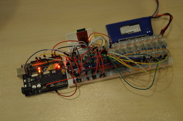
I assembled a scheme on a model board with a single-LED scheme, filled in a sketch example - made sure that everything works as it should:
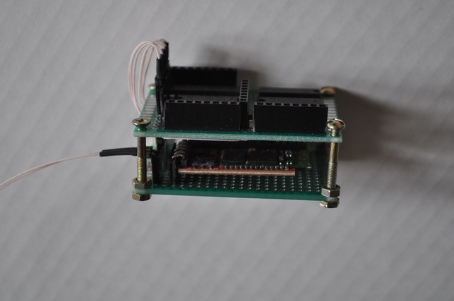
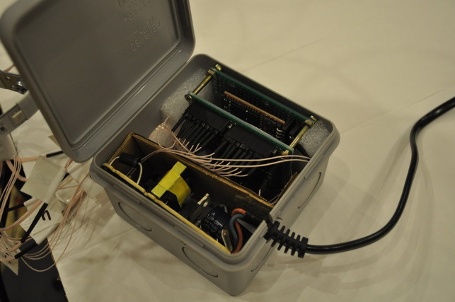
After that, it's time to build the circuit in production version. Since I wanted to assemble the circuit as quickly as possible, and there was no time to try the LUT-technology - I assembled the controller on two textolite layout boards, 4 by 6 cm in size. On the first one there is an arduin and a bluetooth module for remote control, on the second one are registers, keys, and connectors for connecting tapes:
Then twisted both boards together, it turned out a kind of sandwich:
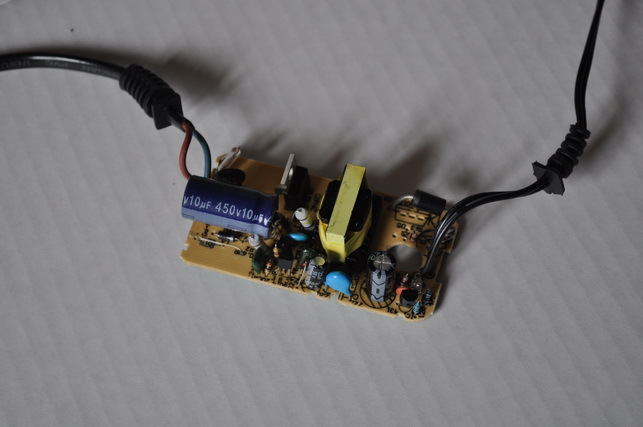
As a power supply, I took inexpensive Chinese, at 12V, with an output current of up to 5A:
As a case, I used a switch box that fit in:
Next - placed inside the case of the power supply, and a sandwich of the boards, stretching the wires from the tapes inside:
It turned out to be a rather compact device, which was easily hidden under the lamp shade so that it did not attract attention.
To control the controller, I previously wrote a program for Android. In general, any bluetooth terminal will be suitable for controlling the circuit - it will suffice to program a few preset commands to transmit, and to select a custom backlight color, specify the RGB color code in R, G, B format.
Next, I provide the sketch code that should be uploaded. The scheme has 10 preset modes, as well as the ability to set its own colors.
Sketch
/* * ShiftPWM non-blocking RGB fades example, (c) Elco Jacobs, updated August 2012. * * This example for ShiftPWM shows how to control your LED's in a non-blocking way: no delay loops. * This example receives a number from the serial port to set the fading mode. Instead you can also read buttons or sensors. * It uses the millis() function to create fades. The block fades example might be easier to understand, so start there. * * Please go to www.elcojacobs.com/shiftpwm for documentation, fuction reference and schematics. * If you want to use ShiftPWM with LED strips or high power LED's, visit the shop for boards. */ // ShiftPWM uses timer1 by default. To use a different timer, before '#include <ShiftPWM.h>', add // #define SHIFTPWM_USE_TIMER2 // for Arduino Uno and earlier (Atmega328) // #define SHIFTPWM_USE_TIMER3 // for Arduino Micro/Leonardo (Atmega32u4) // Clock and data pins are pins from the hardware SPI, you cannot choose them yourself. // Data pin is MOSI (Uno and earlier: 11, Leonardo: ICSP 4, Mega: 51, Teensy 2.0: 2, Teensy 2.0++: 22) // Clock pin is SCK (Uno and earlier: 13, Leonardo: ICSP 3, Mega: 52, Teensy 2.0: 1, Teensy 2.0++: 21) // You can choose the latch pin yourself. const int ShiftPWM_latchPin=8; // ** uncomment this part to NOT use the SPI port and change the pin numbers. This is 2.5x slower ** // #define SHIFTPWM_NOSPI // const int ShiftPWM_dataPin = 11; // const int ShiftPWM_clockPin = 13; // If your LED's turn on if the pin is low, set this to true, otherwise set it to false. const bool ShiftPWM_invertOutputs = false; // You can enable the option below to shift the PWM phase of each shift register by 8 compared to the previous. // This will slightly increase the interrupt load, but will prevent all PWM signals from becoming high at the same time. // This will be a bit easier on your power supply, because the current peaks are distributed. const bool ShiftPWM_balanceLoad = false; #define rxPin 2 #define txPin 4 #include <SoftwareSerial.h> #include <ShiftPWM.h> // include ShiftPWM.h after setting the pins! // Function prototypes (telling the compiler these functions exist). void oneByOne(void); void inOutTwoLeds(void); void inOutAll(void); void alternatingColors(void); void hueShiftAll(void); void randomColors(void); void fakeVuMeter(void); void rgbLedRainbow(unsigned long cycleTime, int rainbowWidth); void printInstructions(void); void setColor(int r, int g, int b); // Here you set the number of brightness levels, the update frequency and the number of shift registers. // These values affect the load of ShiftPWM. // Choose them wisely and use the PrintInterruptLoad() function to verify your load. unsigned char maxBrightness = 255; unsigned char pwmFrequency = 75; unsigned int numRegisters = 6; unsigned int numOutputs = numRegisters*8; unsigned int numRGBLeds = numRegisters*8/3; unsigned int fadingMode = 0; //start with all LED's off. int r = 0; int g = 0; int b = 0; unsigned long startTime = 0; // start time for the chosen fading mode SoftwareSerial mySerial = SoftwareSerial(rxPin, txPin); void setup(){ while(!Serial){ delay(100); } Serial.begin(9600); pinMode(rxPin, INPUT); pinMode(txPin, OUTPUT); // Sets the number of 8-bit registers that are used. ShiftPWM.SetAmountOfRegisters(numRegisters); // SetPinGrouping allows flexibility in LED setup. // If your LED's are connected like this: RRRRGGGGBBBBRRRRGGGGBBBB, use SetPinGrouping(4). ShiftPWM.SetPinGrouping(1); //This is the default, but I added here to demonstrate how to use the funtion ShiftPWM.Start(pwmFrequency,maxBrightness); printInstructions(); mySerial.begin(9600); } void loop() { String command = ""; while (mySerial.available() > 0) { char c = mySerial.read(); Serial.println(c); command.concat(c); } command.trim(); if (command == "") { } else { startTime = millis(); } int firstCommaPos = -1; int lastCommaPos = -1; firstCommaPos = command.indexOf(','); lastCommaPos = command.lastIndexOf(','); if (firstCommaPos != -1 && lastCommaPos != -1 && lastCommaPos != firstCommaPos) { String rStr = command.substring(0, firstCommaPos); String gStr = command.substring(firstCommaPos + 1, lastCommaPos); String bStr = command.substring(lastCommaPos + 1); // Serial.println("r is -> " + rStr); // Serial.println("g is -> " + gStr); // Serial.println("b is -> " + bStr); r = rStr.toInt(); g = gStr.toInt(); b = bStr.toInt(); fadingMode = 10; } if (command == "a") fadingMode = 0; if (command == "b") fadingMode = 1; if (command == "c") fadingMode = 2; if (command == "d") fadingMode = 3; if (command == "e") fadingMode = 4; if (command == "f") fadingMode = 5; if (command == "g") fadingMode = 6; if (command == "h") fadingMode = 7; if (command == "i") fadingMode = 8; if (command == "j") fadingMode = 9; Serial.println("command is -> " + command); switch(fadingMode){ case 0: // Turn all LED's off. ShiftPWM.SetAll(0); break; case 1: oneByOne(); break; case 2: inOutAll(); break; case 3: inOutTwoLeds(); break; case 4: alternatingColors(); break; case 5: hueShiftAll(); break; case 6: randomColors(); break; case 7: fakeVuMeter(); break; case 8: rgbLedRainbow(3000,numRGBLeds); break; case 9: rgbLedRainbow(10000,5*numRGBLeds); break; case 10: setColor(r,g,b); break; default: Serial.println("Unknown Mode!"); delay(1000); break; } } void setColor(int r, int g, int b) { ShiftPWM.SetAll(0); ShiftPWM.SetAllRGB(r,g,b); } void oneByOne(void){ // Fade in and fade out all outputs one at a time unsigned char brightness; unsigned long fadeTime = 500; unsigned long loopTime = numOutputs*fadeTime*2; unsigned long time = millis()-startTime; unsigned long timer = time%loopTime; unsigned long currentStep = timer%(fadeTime*2); int activeLED = timer/(fadeTime*2); if(currentStep <= fadeTime ){ brightness = currentStep*maxBrightness/fadeTime; ///fading in } else{ brightness = maxBrightness-(currentStep-fadeTime)*maxBrightness/fadeTime; ///fading out; } ShiftPWM.SetAll(0); ShiftPWM.SetOne(activeLED, brightness); } void inOutTwoLeds(void){ // Fade in and out 2 outputs at a time unsigned long fadeTime = 500; unsigned long loopTime = numOutputs*fadeTime; unsigned long time = millis()-startTime; unsigned long timer = time%loopTime; unsigned long currentStep = timer%fadeTime; int activeLED = timer/fadeTime; unsigned char brightness = currentStep*maxBrightness/fadeTime; ShiftPWM.SetAll(0); ShiftPWM.SetOne((activeLED+1)%numOutputs,brightness); ShiftPWM.SetOne(activeLED,maxBrightness-brightness); } void inOutAll(void){ // Fade in all outputs unsigned char brightness; unsigned long fadeTime = 2000; unsigned long time = millis()-startTime; unsigned long currentStep = time%(fadeTime*2); if(currentStep <= fadeTime ){ brightness = currentStep*maxBrightness/fadeTime; ///fading in } else{ brightness = maxBrightness-(currentStep-fadeTime)*maxBrightness/fadeTime; ///fading out; } ShiftPWM.SetAll(brightness); } void alternatingColors(void){ // Alternate LED's in 6 different colors unsigned long holdTime = 2000; unsigned long time = millis()-startTime; unsigned long shift = (time/holdTime)%6; for(unsigned int led=0; led<numRGBLeds; led++){ switch((led+shift)%6){ case 0: ShiftPWM.SetRGB(led,255,0,0); // red break; case 1: ShiftPWM.SetRGB(led,0,255,0); // green break; case 2: ShiftPWM.SetRGB(led,0,0,255); // blue break; case 3: ShiftPWM.SetRGB(led,255,128,0); // orange break; case 4: ShiftPWM.SetRGB(led,0,255,255); // turqoise break; case 5: ShiftPWM.SetRGB(led,255,0,255); // purple break; } } } void hueShiftAll(void){ // Hue shift all LED's unsigned long cycleTime = 10000; unsigned long time = millis()-startTime; unsigned long hue = (360*time/cycleTime)%360; ShiftPWM.SetAllHSV(hue, 255, 255); } void randomColors(void){ // Update random LED to random color. Funky! unsigned long updateDelay = 100; static unsigned long previousUpdateTime; if(millis()-previousUpdateTime > updateDelay){ previousUpdateTime = millis(); ShiftPWM.SetHSV(random(numRGBLeds),random(360),255,255); } } void fakeVuMeter(void){ // imitate a VU meter static unsigned int peak = 0; static unsigned int prevPeak = 0; static unsigned long currentLevel = 0; static unsigned long fadeStartTime = startTime; unsigned long fadeTime = (currentLevel*2);// go slower near the top unsigned long time = millis()-fadeStartTime; currentLevel = time%(fadeTime); if(currentLevel==peak){ // get a new peak value prevPeak = peak; while(abs(peak-prevPeak)<5){ peak = random(numRGBLeds); // pick a new peak value that differs at least 5 from previous peak } } if(millis() - fadeStartTime > fadeTime){ fadeStartTime = millis(); if(currentLevel<peak){ //fading in currentLevel++; } else{ //fading out currentLevel--; } } // animate to new top for(unsigned int led=0;led<numRGBLeds;led++){ if(led<currentLevel){ int hue = (numRGBLeds-1-led)*120/numRGBLeds; // From green to red ShiftPWM.SetHSV(led,hue,255,255); } else if(led==currentLevel){ int hue = (numRGBLeds-1-led)*120/numRGBLeds; // From green to red int value; if(currentLevel<peak){ //fading in value = time*255/fadeTime; } else{ //fading out value = 255-time*255/fadeTime; } ShiftPWM.SetHSV(led,hue,255,value); } else{ ShiftPWM.SetRGB(led,0,0,0); } } } void rgbLedRainbow(unsigned long cycleTime, int rainbowWidth){ // Displays a rainbow spread over a few LED's (numRGBLeds), which shifts in hue. // The rainbow can be wider then the real number of LED's. unsigned long time = millis()-startTime; unsigned long colorShift = (360*time/cycleTime)%360; // this color shift is like the hue slider in Photoshop. for(unsigned int led=0;led<numRGBLeds;led++){ // loop over all LED's int hue = ((led)*360/(rainbowWidth-1)+colorShift)%360; // Set hue from 0 to 360 from first to last led and shift the hue ShiftPWM.SetHSV(led, hue, 255, 255); // write the HSV values, with saturation and value at maximum } } void printInstructions(void){ Serial.println("---- ShiftPWM Non-blocking fades demo ----"); Serial.println(""); Serial.println("Type 'l' to see the load of the ShiftPWM interrupt (the % of CPU time the AVR is busy with ShiftPWM)"); Serial.println(""); Serial.println("Type any of these numbers to set the demo to this mode:"); Serial.println(" 0. All LED's off"); Serial.println(" 1. Fade in and out one by one"); Serial.println(" 2. Fade in and out all LED's"); Serial.println(" 3. Fade in and out 2 LED's in parallel"); Serial.println(" 4. Alternating LED's in 6 different colors"); Serial.println(" 5. Hue shift all LED's"); Serial.println(" 6. Setting random LED's to random color"); Serial.println(" 7. Fake a VU meter"); Serial.println(" 8. Display a color shifting rainbow as wide as the LED's"); Serial.println(" 9. Display a color shifting rainbow wider than the LED's"); Serial.println(""); Serial.println("Type 'm' to see this info again"); Serial.println(""); Serial.println("----"); } The video shows the rainbow mode, IMHO the most beautiful mode of operation:
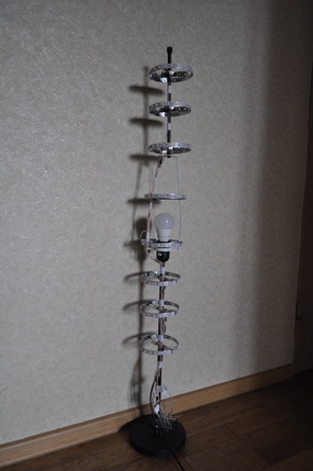
And a couple of photos of the finished device - it's a pity that the camera can not convey the richness of color:
 |  |
Results
The assembled lamp fully satisfies the original idea, looks like a finished product, the wires do not stick out, is controlled easily, the son is satisfied - and this is the main thing!
All components of the controller were purchased on Ebee, everyone can find them there - the prices are minimal. The total cost of the lamp turned out to be approximately: 500r lamp itself, 800r for the LED strip, 100r for the power supply unit, microcircuits for 50r, 200r for the broom, case and steel tape for fastening for 200r. Total - about 1900r.
By the time the assembly took about 2 weeks in free time in the evenings. Surely you can do it faster if you do not get distracted.
What else can you do:
- Use LUT instead of mockups
- Modify the software for the phone - so that you can adjust the brightness / speed of effects, etc.
- Instead of Adruinka, take Raspberry - and be able to automatically turn on the lights, manually control the existing modes or create new ones without reloading the firmware
- Instead of 5050 ribbons, take the ws2811 ribbon - and get the ability to control not the levels entirely, but each individual LED
- Now the stock light has nothing to do with the microcontroller - or you can install a relay and control it remotely from the phone as well
- Make the inclusion of the clap of his hands - so as not to climb every time in the program to include
- ...
- Dozens of dodelok
I would be glad to see in comments reviews, criticism, and ideas about improving the design.
Source: https://habr.com/ru/post/258291/
All Articles