Energia Launchpad wireless electronic lock

Looking at the many arduino-based Habro articles it seemed to me a bit strange that there was no interesting wireless solutions from the world of Energia Launchpad. It is time to correct this universal injustice!
Today, I will introduce you to the CC3200-launchpad debug card, talk about its advantages over the ESP8266, connect a launchpad to it via radio and click on the big Soviet relays. Go!
CC3200-LAUNCHXL Lunchpad with a capital letter
I’ll start today's story with a CC3200 [1] microcontroller by Texas Instruments.
This controller is a symbiosis of the TIVA-C Cortex-M4 core and the Simplelink Wi-Fi CC3100 processor in one package
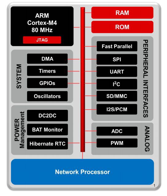
Figure 1: Controller block diagram
')
A little about the pleasant and interesting properties of this stone, applicable to embedded micropower solutions [2]:
- 80MHz Cortex-M4 core;
- 256K RAM;
- Peripheral driver in the ROM, there is no built-in Flash program memory;
- Support for external chip Serial Flash memory - hang as much as you want;
- Hardware encryption AES, DES, SHA2, MD5, CRC;
- 2xI2S, 1xSD-card, 2xUART, 1xSPI, 1x2C, 8-bit camera interface;
- 4 timers with 16-bit PWM;
- 4 channels of 12-bit ADC
- Certified 802.11g / b / n Wi-Fi module with support for WEP encryption, WPA2-PSK and WPA-Enterprise. Work in both device mode and host mode
- 256-bit AES for SSLv3 and TSLv1. Yes, yes, he drags SSL!
- Power consumption and multiple power management modes
CC3200 vs ESP8266
On the one hand, the ESP8266 has the following advantages:
First of all, it is very small and integrated - a crap the size and cost of a coin requires only a couple of batteries and it can already be plugged into an iron or kettle.
Secondly, he has a well-developed dietary regimes - if you go wisely, you get a diet product.
Thirdly, he has a simple start - just connect it to the computer, open the Arduino environment and you can work.
On the other hand, the CC3200 is a powerful processor capable of holding many active tasks. In addition, it has a much richer periphery - if you want - connect the camera, you want audio devices (via I2S) or an SD card. If you want - hang out with a dozen of all sorts of things - it will withstand both hardware and firmware. And of course SSL. Here, my little paranoid simply exults with happiness.
But then the toad wakes up and begins to choke your humble servant - the lunchpad from the manufacturer costs 30 bucks / piece. In the Russian Federation there is a chance to buy for 40-50 dollars + shipping. TI's free shipping is over.
In any case, each option has its own niche of use.
CC3200-LAUNCHXL Quick Start [3]

Figure 2: equipment
Like any lunchpad, the CC3200 comes in a neat cardboard box with basic equipment - the board itself, a micro USB cable, a couple of jumpers and a couple of booklets.
The board is a typical representative of a 40-pin launchpad, bears on itself the CC3200 controller itself in a 64-foot QFN package. Not the worst case for manual soldering. Also, the board has a programmer based on the FT2232 chip (official openOCD support). Chip of Flash of memory on 8 Mbit of data.
We should also mention the three-axis + -16G accelerometer BMA222 [4] and the non-contact IR temperature sensor TMP006 [5]
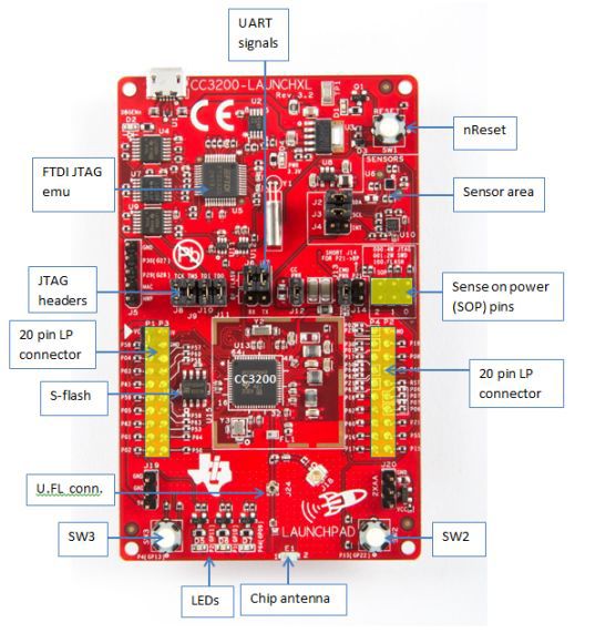
Figure 3: Lunchpad in Detail
In a word, all that a growing IoT developer needs.
Let's connect the board to the power supply and examine the demo firmware available on it.
The firmware offers some datasheets, and 4 micro-devices. And all this in access point mode, with an http server on board.
In order not to be wordy, a small video review:
CC3200 SDK [6]
With CCS UniFlash [7] we will update our SDK.

Figure 4: CCS UniFlash Appearance
To begin with, the board needs to be switched to the Flash programming mode, for which close pins 2 of the SOP connectors. After that, we connect to the UART port, format the Flash memory according to the size of 1 MB. Then we specify the path to our ServicePack. at the time of this writing, the current Service Pack: 1.0.0.10.0, SDK: 1.1.0.
Programming in Code Composer Studio 6.0.1 [8]
For large projects and normal debugging, the ideal option is to develop programs in the Code Composer Studio environment (note-taking - CCS6 is free for any use when using the GCC compiler). The manufacturer also supports IAR.
Install and configure CCS IDE
First of all, let's configure the jumpers as shown in the figure:
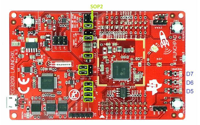
Figure 5: Installation of jumpers for programming in the CCS environment
In addition, installing the Code Composer Studio we will not forget to tick the corresponding package:
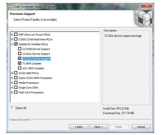
Figure 6: CCS installation with CC3200 support
If you are a TI-RTOS lover [9], I recommend installing the TI-RTOS for SImplelink package after installing it in the extension store.

Figure 7: TI-RTOS installation for CC3100 & CC3200
Figure 5: Installation of jumpers for programming in the CCS environment
In addition, installing the Code Composer Studio we will not forget to tick the corresponding package:
Figure 6: CCS installation with CC3200 support
If you are a TI-RTOS lover [9], I recommend installing the TI-RTOS for SImplelink package after installing it in the extension store.
Figure 7: TI-RTOS installation for CC3100 & CC3200
We import one of the demo projects. I chose the HTTP server [10].
Our task is to add a target to connect to the board. To do this, go to the menu item View-> Target Configurations, import the file C: \ TI \ CC3200SDK_1.1.0 \ cc3200-sdk \ tools \ ccs_patch \ cc3200.ccxml and then specify in its context menu that it will be used by default .
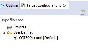
Figure 7: Configuring the debug interface
Hit F11 to start the Debug mode, then F8 to start the program and climb into the Wi-Fi Starter app for Android [11] or iOS [12]
Wi-Fi starter
Specifying the name of the access point and the password to it, press the start button
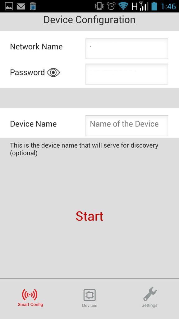
Figure 8: Search and configure devices
Once the device is found, it appears in the Devices tab.
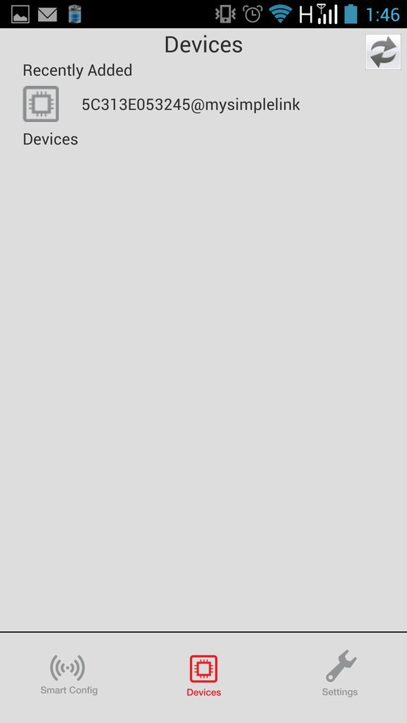
Figure 9: List of connected devices
Tap on it and get to the page in the browser, which says that everything works. You can also reconfigure data for Wi-Fi connection and switch the device to the access point mode.
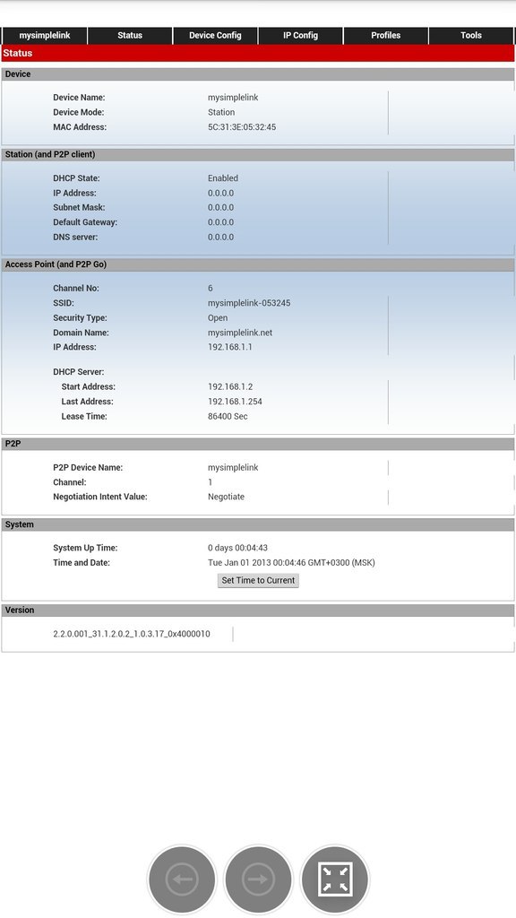
Figure 10: Demo application
Figure 8: Search and configure devices
Once the device is found, it appears in the Devices tab.
Figure 9: List of connected devices
Tap on it and get to the page in the browser, which says that everything works. You can also reconfigure data for Wi-Fi connection and switch the device to the access point mode.
Figure 10: Demo application
Then we can climb where we need and do not need and write our applications.
Creating an electronic lock
Let us finally go to practice!
Let's make an electronic lock with a door-opening sensor and a remote control for management, so that with unauthorized access I receive SMS with indecent content.
For this we need:
- CC3200 launchpad as a Wi-Fi gateway
- TIVA-C launchpad [13] as an electronic lock control card
- MSP430F5529 [14] launchpad as a remote key board
- and three pieces of Anaren CC110L boosterpack radio modules as radio modules [15].
The principle of operation is as follows:
The actuator is equipped with a two-position solenoid and a perimeter sensor. In our case, the role of the solenoid will be performed by the two-position Soviet relay RP-12 [16], and the role of the perimeter sensor of the RF-8300 photocell, so familiar to the heart of a visitor to the Soviet subway (not a single turnstile was harmed). The logic of operation is as follows: With the help of a radio command, you can set up either the standby mode or the armed mode. In the security mode, the solenoid “locks” the door, and triggering the sensor will trigger an alarm. Switching to standby mode unlocks the door. The status is regularly transmitted to the Wi-Fi gateway via a radio channel.
The key fob has two buttons - to arm / unset. Commands are transmitted directly to the actuator. UDP data transfer type, i.e. without confirmation of receipt of the package (lip will crack). Data is transferred without encryption for the same reason. The executive sends its state to the wi-fi gateway. In the event of a Wi-Fi alarm, the gateway initiates SMS transmission.
Fix the commands:
enum {IDLE=0x01, ACTIVE, ALERT}; Energia Programming [17]
For Arduino fans applicable to the launchpad, there is a wonderful fork in the form of the Energia programming environment. He is actively supported by the community:
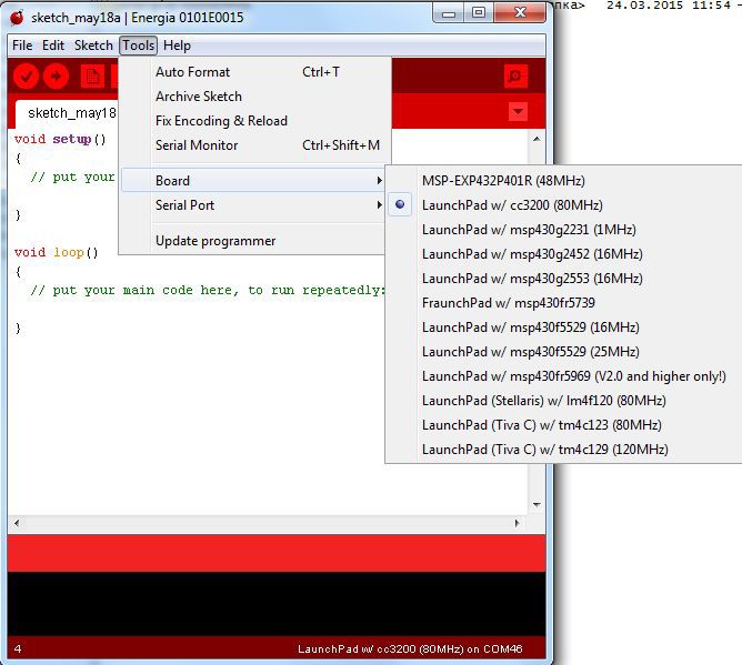
Figure 11: List of boards supported by Energia-15
In order for the CC3200 to be programmed from Energia, you need to make a small hack - connect the top TCK pin with the bottom pin SOP-2:

Figure 12: Connecting Auto-Programming Mode
Trinket
Everything is simple here. Pushed the button 1 - transferred the ACTIVE command to the mechanism.
pressed button 2 - the IDLE command was transmitted to the mechanism.

Figure 13. Components of the keychain
Nakopipastim example of a simple program:
Program Listing for Keychain
#include <SPI.h> #include <AIR430BoostETSI.h> //define addresses. #define ADDRESS_LOCAL 0x02 #define ADDRESS_REMOTE 0x03 //FSM states. And commands enum { IDLE=0x01, ACTIVE, ALERT}; unsigned char txData[60] = { "\0" }; const int setButton = PUSH1; //set to active mode const int releaseButton = PUSH2;//set to idle mode const int ledPin = GREEN_LED; const int redPin = RED_LED; void setup() { //define pinouts and add serial outputr pinMode(ledPin, OUTPUT); pinMode(redPin, OUTPUT); Serial.begin(9600); pinMode(setButton, INPUT_PULLUP); pinMode(releaseButton, INPUT_PULLUP); Radio.begin(ADDRESS_LOCAL, CHANNEL_1, POWER_MAX); Serial.println("RF start"); txData[0] = ADDRESS_LOCAL;//set zer0 byte as our address } void loop(){ //check set button if (digitalRead(setButton) == LOW){ //if button is pressed, send command Serial.println("Active mode"); digitalWrite(redPin, HIGH); txData[1] = ACTIVE;//Set command txData[2] = 0x00; Radio.transmit(ADDRESS_REMOTE, (unsigned char*)&txData, 2); } else{ digitalWrite(redPin, LOW); } //check release button if (digitalRead(releaseButton) == LOW){ Serial.println("IDLE mode"); digitalWrite(ledPin, HIGH); txData[1] = IDLE;//Set command txData[2] = 0x00; //send packet Radio.transmit(ADDRESS_REMOTE, (unsigned char*)&txData, 2); } else{ digitalWrite(ledPin, LOW); } sleepSeconds(1);//Low-power mode delay delay(50);//to Clock stabilization } Actuating mechanism
The task of the actuator is to control a double-solenoid. Such a solenoid has two windings, applying voltage to one winding, we retract the core, and release it to the other. Constantly hold the voltage on the windings is not required. Our RP-12 relay is a bit different - it has one winding, and the choice of action is determined by polarity. We will manage a pair of diodes.
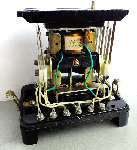
Figure 14: The great Soviet relay without cuts. The electromagnet and the two-position core are visible. Giving a signal of different polarity to the core we achieve switching of the relay.
We will connect through the MOC3052 triacs as follows:
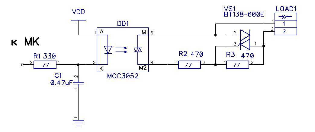
Figure 15: Triac wiring diagram.
I found a scarf with two triacs in my zagashniki, so I didn’t have to fence the mockup.
The perimeter control sensor on the RF-8300 photoelectric sensor operates autonomously, with a group of closing contacts, giving a signal to the actuator.
google cardboard fans
The lenses of these relyuhs are simply created in order to stand in glasses of virtual reality.
Having received a command from the key fob, we execute it and duplicate it on the wi-Fi gateway.
Copy-paste program:
Program listing for actuator
#include <SPI.h> #include <AIR430BoostETSI.h> #define ADDRESS_LOCAL 0x03 #define ADDRESS_REMOTE 0x01 unsigned char rxData[60] = { "\0" }; unsigned char txData[60] = { "\0" }; /* Finite state machine: 1. IDLE mode 2. Action Mode 3. Alert mode 1 -> 2 Received command 0x01 2 -> 1 received command 0x02 2 -> 3 sensor triggered. Send alert */ enum {IDLE=0x01, ACTIVE, ALERT}; unsigned int fsm = IDLE; static unsigned char sensor = 11; static unsigned char releopen = 9; static unsigned char releclose = 10; static unsigned char releopenled = BLUE_LED; static unsigned char relecloseled = GREEN_LED; // ----------------------------------------------------------------------------- // Main example void setup() { pinMode(sensor, INPUT_PULLUP); pinMode(releopen, OUTPUT); digitalWrite(releopen, HIGH); pinMode(releopenled, OUTPUT); pinMode(relecloseled, OUTPUT); pinMode(releclose, OUTPUT); digitalWrite(releclose, HIGH); pinMode(12, OUTPUT); pinMode(12, LOW); //return pin for sensor Radio.begin(ADDRESS_LOCAL, CHANNEL_1, POWER_MAX); // Setup serial for debug printing. Serial.begin(9600); txData[0] = ADDRESS_LOCAL;//set zer byte as our address } uint8_t length = 0; void loop() { switch (fsm){ case IDLE: length = Radio.receiverOn(rxData, sizeof(rxData), 1000); if (length > 0){ if (rxData[1] == ACTIVE){ //change state stage fsm = ACTIVE; txData[1] = ACTIVE;//Set command txData[2] = 0x00; Radio.transmit(ADDRESS_REMOTE, (unsigned char*)&txData, 2); //send 500ms inpuls to actuator digitalWrite(releclose, LOW); digitalWrite(relecloseled, HIGH); delay(500); digitalWrite(releclose, HIGH); digitalWrite(relecloseled, LOW); } else{ fsm = IDLE; } } else{ } break; case ACTIVE: length = Radio.receiverOn(rxData, sizeof(rxData), 100); if (length > 0){ if (rxData[1] == IDLE){ //change state stage fsm = IDLE; txData[1] = IDLE;//Set command txData[2] = 0x00; Radio.transmit(ADDRESS_REMOTE, (unsigned char*)&txData, 2); //send 500ms inpuls to actuator digitalWrite(releopen, LOW); digitalWrite(releopenled, HIGH); delay(500); digitalWrite(releopen, HIGH); digitalWrite(releopenled, LOW); } else{ fsm = ACTIVE; } } else{ } checkperimeter(); break; case ALERT: length = Radio.receiverOn(rxData, sizeof(rxData), 1000); if (length > 0){ if (rxData[1] == IDLE){ //change state stage fsm = IDLE; txData[1] = IDLE;//Set command txData[2] = 0x00; Radio.transmit(ADDRESS_REMOTE, (unsigned char*)&txData, 2); //send 500ms inpuls to actuator digitalWrite(releopen, LOW); digitalWrite(releopenled, HIGH); delay(500); digitalWrite(releopen, HIGH); digitalWrite(releopenled, LOW); } else{ fsm = ALERT; } } else{ } break; default: break; } } void checkperimeter(){ uint8_t sensorstate = digitalRead(sensor); if (sensorstate == LOW){ Serial.println("Alert!"); //alert!! fsm = ALERT; txData[1] = ALERT;//Set command txData[2] = 0x00; Radio.transmit(ADDRESS_REMOTE, (unsigned char*)&txData, 2); } } Gateway
The task of the gateway is no more difficult - to duplicate the system status with LEDs (for testing) and in case of alarm send a message to the phone.

Figure 15: Gateway Assembly
Temboo + NEXMO
But first let's prepare the API soil. To do this, we register on the services Temboo [18] and Nexmo [19]. Nexmo's tasks include connecting to any mobile phone anywhere in the world. When registering, they give starting 2 Euros, which is enough to try out this service.
The tasks of Temboo will include the organization of communication between our device and the Nexmo service. Here for start 250 requests are given which can be expanded for free by a good ten thousand, inviting friends. As for the tariffs - text messages cost me 2 eurocents per share.
In the list of possible APIs, select Nexmoo.SMS.TextMessage.
Choose our board - CC3200 and specify the Wi-Fi connection parameters

Figure 16: Wi-Fi Setup
Specify the connection settings. We are required to specify the API keys from our Nexmoo account, the sender's phone number, which is associated with our account, the recipient's phone number and a text message.
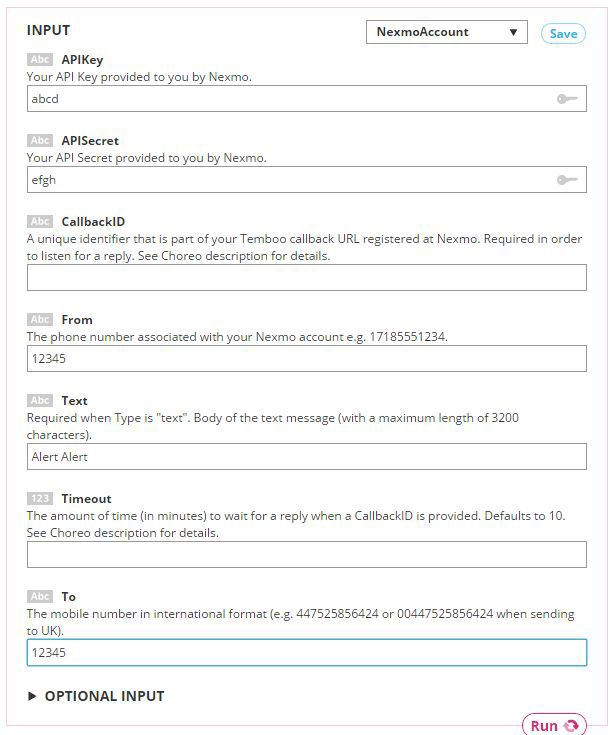
Figure 17: Recipient selection and message setup
By clicking on the Run button you can check that everything works.
Copy-paste the code from the blocks and “add up” its support for the operation modes:
Code listing for Wi-Fi gateway
#include <SPI.h> #include <AIR430BoostETSI.h> #include <WiFi.h> #include <WiFiClient.h> #include <Temboo.h> #include "TembooAccount.h" // Contains Temboo account information WiFiClient client; #define ADDRESS_LOCAL 0x01 unsigned char rxData[60] = { "\0" }; unsigned char txData[60] = { "\0" }; /* Finite state machine: 1. IDLE mode 2. Action Mode 3. Alert mode 1 -> 2 Received command 0x01 2 -> 1 received command 0x02 2 -> 3 sensor triggered. Send alert */ enum { IDLE=0x01, ACTIVE, ALERT}; unsigned int fsm = IDLE; // ----------------------------------------------------------------------------- // Main example void setup() { pinMode(GREEN_LED, OUTPUT); pinMode(RED_LED, OUTPUT); pinMode(YELLOW_LED, OUTPUT); digitalWrite(YELLOW_LED, LOW); digitalWrite(RED_LED, LOW); digitalWrite(GREEN_LED, LOW); Radio.begin(ADDRESS_LOCAL, CHANNEL_1, POWER_MAX); // Setup serial for debug printing. txData[0] = ADDRESS_LOCAL;//set zer byte as our address Serial.begin(9600); int wifiStatus = WL_IDLE_STATUS; // Determine if the WiFi Shield is present Serial.print("\n\nShield:"); if (WiFi.status() == WL_NO_SHIELD) { Serial.println("FAIL"); // If there's no WiFi shield, stop here while(true); } Serial.println("OK"); // Try to connect to the local WiFi network while(wifiStatus != WL_CONNECTED) { Serial.print("WiFi:"); wifiStatus = WiFi.begin(WIFI_SSID, WPA_PASSWORD); if (wifiStatus == WL_CONNECTED) { Serial.println("OK"); } else { Serial.println("FAIL"); } delay(5000); } digitalWrite(YELLOW_LED, HIGH); Serial.println("Setup complete.\n"); } uint8_t length = 0; void loop() { length = Radio.receiverOn(rxData, sizeof(rxData), 1000); if (length > 0){ Serial.print("Get state: "); Serial.println(rxData[1], DEC); switch (fsm){ case IDLE: if (rxData[1] == ACTIVE){ fsm = ACTIVE; digitalWrite(GREEN_LED, HIGH); } break; case ACTIVE: if (rxData[1] == IDLE){ fsm = IDLE; digitalWrite(GREEN_LED, LOW); digitalWrite(RED_LED, LOW); } if (rxData[1] == ALERT){ fsm = ALERT; digitalWrite(RED_LED, HIGH); sendmessage(); } break; case ALERT: if (rxData[1] == IDLE){ fsm = IDLE; digitalWrite(GREEN_LED, LOW); digitalWrite(RED_LED, LOW); } break; } } } void sendmessage(){ Serial.println("Running SendMessage - Run #" + String(numRuns++)); TembooChoreo SendMessageChoreo(client); // Invoke the Temboo client SendMessageChoreo.begin(); // Set Temboo account credentials SendMessageChoreo.setAccountName(TEMBOO_ACCOUNT); SendMessageChoreo.setAppKeyName(TEMBOO_APP_KEY_NAME); SendMessageChoreo.setAppKey(TEMBOO_APP_KEY); // Set Choreo inputs String TextValue = "Testing! Testing! 1, 2, 3"; SendMessageChoreo.addInput("Text", TextValue); String APIKeyValue = "000"; SendMessageChoreo.addInput("APIKey", APIKeyValue); String ToValue = "000"; SendMessageChoreo.addInput("To", ToValue); String APISecretValue = "000"; SendMessageChoreo.addInput("APISecret", APISecretValue); String FromValue = "000"; SendMessageChoreo.addInput("From", FromValue); // Identify the Choreo to run SendMessageChoreo.setChoreo("/Library/Nexmo/SMS/SendMessage"); // Run the Choreo; when results are available, print them to serial SendMessageChoreo.run(); while(SendMessageChoreo.available()) { char c = SendMessageChoreo.read(); Serial.print(c); } SendMessageChoreo.close(); } We compile, poke buttons and make sure that everything works.
Demonstration
Visual demonstration with large relyushki:
To summarize - the CC3200 debug board is a very nice piece of hardware that has its own niche for applications. The demo shown here is made on the principle of “blind from what was” and is intended to show a part of the capabilities of the Energia lauchpad boards. The plans - in detail to tell about the features of connecting sensors and actuators, taking into account the reliability and resistance to electromagnetic interference.
The source code of the project is available in the repository [20].
Useful links:
1. CC3200 Product Brief http://www.ti.com/product/cc3200
2. CC3200 Datasheet http://www.ti.com/lit/ds/symlink/cc3200.pdf
3. CC3200-LAUNCHXL User Guide http://www.ti.com/lit/ug/swru372b/swru372b.pdf
4. BMA222 Accelerometer Datasheet https://ae-bst.resource.bosch.com/media/products/dokumente/bma222/bst-bma222-ds002-05.pdf
5. TMP006 IR Thermopile Sensor Datasheet http://www.ti.com/lit/ds/sbos518e/sbos518e.pdf
6. CC3200 SDK http://www.ti.com/tool/cc3200sdk
7. CCS UniFlash http://www.ti.com/tool/uniflash
8. Code Composer Studio 6 IDE http://www.ti.com/tool/ccstudio
9. TI-RTOS http://www.ti.com/tool/TI-RTOS
10. CC3200 HTTP server User Guide http://processors.wiki.ti.com/index.php/CC32xx_HTTP_Server
11. Wi-Fi Starter App for Android https://play.google.com/store/apps/details?id=com.pandaos.smartconfig
12. Wi-Fi Starter App for iOS https://itunes.apple.com/us/app/texas-instruments-simplelink/id884122493?ls=1&mt=8
13. TIVA-C launchpad http://www.ti.com/tool/ek-tm4c123gxl
14. MSP430F5529 launchpad http://www.ti.com/tool/msp-exp430f5529lp
15. CC110L Air Module Boosterpack https://www.anaren.com/air/cc110l-air-module-boosterpack-embedded-antenna-module-anaren
16, Relay RP-12. Description: http://www.cheaz.ru/ru/production/ustroystva-releynoy-zashchity/rele-promezhutochnye-dvukhpozitsionnye-rp-8-9-11-12
17. Energia IDE http://energia.nu/
18. Temboo https://temboo.com/
19. Nexmo https://www.nexmo.com/
20. Electronic Lock GitHub repo https://github.com/radiolok/electronic_lock_energia
Source: https://habr.com/ru/post/258155/
All Articles