What does it mean to develop a robot
You read about robots and programming and think: “It would be great to do something like this on your own!” Those who take this idea a little more just look at who and how did their robot do. Read articles, watch videos. The pictures are clear. In the videos, ready-made products are also usually shown, as well as their production technologies. And it seems that everything is clear: sawed off, screwed, soldered, connected, programmed out on that program with this code.
Even more enthusiastic, choosing an interesting and, at first glance, simple option, go into action and, often copying, make their first robot. This is a strong-willed and very significant decision - the main thing is to start at least do something yourself! In the process of manufacturing, there is a lot of technological stumbles up to the point that it turns out for ordering / buying some items, you need to find out how exactly it is called. And yet - the connectors are not soldered normally - and how does everything work with a one-touch video? The creation process is often delayed, but the persistent beginner robotics somehow finishes the result to some meaningful first launch at least “in a straight line”.
')
Then, when the robot is finished, there comes an understanding of why everything is being done this way and in that sequence. The creation process can already be somehow realized, formalized, painted. It is from this moment that the development of the model of the next, second generation begins.
Yes, I also read articles with interest before. And now I read! I especially like articles about copters: from the ground, yes to heaven! However, to be honest, they caused only thoughts in me. Moreover, it was necessary to understand programming, and the last time I worked with C at the institute, everything was completely forgotten. I know what Arduino is, but I have never seen it live. And so on. I have a technical education, I deal with DSP on FPGA. Technically, there are no obstacles for me to take and figure out, but ... in fact, I do all this at work and I have all this business there, as they say, "above the roof." As a result, I needed some kind of good incentive to somehow start doing this. Stimulus appeared when it became necessary for someone else: the truth is that real creation is when you give to others.
My good friend, who is one of the founders of Endurance , a young (one might say freshly baked) company, knowing the nature of my work, turned to me on a number of technical issues. It turned out that the guys have developers in the USA and have already presented their prototype of the super-cheap (phone + plastic platform with wheels on the Arduin - it seems to be cheaper and nowhere) a telepresence robot. But they wanted not just to do one marketing and business in the style of “bought there - sold here”, but they wanted to immerse themselves in more detail into a technical topic and even plan to develop their own model (even if equivalent in principle and functionality), but here in Russia, in order to obtain not only the finished result, but also understandable by the technology of its manufacture. Such is the premise of participation in this matter of your humble servant (I hint at myself).
At first, I also read articles, looked where they buy and how they do it. But there was no single picture. It seems that, in general, everything is clear, but at the same time not everything. It is not clear how to control from a computer, how to deliver video to a computer. Moreover, I am not a softphone and I would not like to “dig out” this, soft, theme from scratch, although it would be interesting, of course; so I somehow successfully satisfied all my needs with the AutoIt scripting language. As a result of the search, I found two key resources that have become key for me: the online store carduino and the cyber-place forum. The store could buy all the necessary components - all in one place.
Prices, compared with ebay or ali, of course, wild, but the main thing was not the case - you could buy a platform and the necessary body kit for it, as well as all small things. And it was convenient to pick up / order. At the forum in the section "Do it yourself" \ "Robotics" and "Do it yourself" \ "CyberWrt" you can learn general information, as well as how to organize a detailed computer connection with the robot via Wi-Fi. Ten years of experience in the specialty made me feel, and instead of immediately starting to copy, twisting or programming something, I picked up a pencil and paper ...
What does “develop” mean? It is clear what “make a robot” means - you take it and ... you do it! And how to “develop” it?
Below I tried to describe the process, namely, development, and not the creation of a robot. The creation of a robot, as a construction, is initially intuitive and understandable. As the creation is screwed this - this, this - this. Ponakrutil so - and suddenly it turned out that the second part, it is necessary to fasten otherwise, then the eighth part will stand up like a glove, you just need to move the wiring from the batteries to the left closer to the fifth part, and in order not to dangle, it is better to attach to the fourth, slightly turning them as there will be the tenth part there. Sheer creativity. And let's try for an adult: first we will think about what we will do, and then we will do it :)
So, what will be discussed in this article. I decided not to write about how I did the robot, there are a lot of such articles and there is no sense in the appearance of another one. I’m certainly not the first, or even the tenth, who on the purchase platform, having mounted the sensors, made the toy to the delight of myself and others. I decided to try, so to speak, to state my technology of thinking. I tried to convey to readers not just the fact that it is not so difficult to make a robot, but to explain the methodology by which you can take and try to make your robot from scratch, and the beginning of robotics will be clear and understandable the steps of creation initially, rather than opening advancement into the unknown.
Imagine a person who has never worked on robotics. He has a friend, a soldering iron, a multimeter and any hand tools such as nippers, screwdrivers and others. Introduced yourself? Fine! Go…
The first stage - understanding
What do we want to do? And why is it necessary?
For me, this issue was initially resolved for me - I need to make a machine with a video camera that could connect via Wi-Fi or the Internet to a computer, on the computer I would see the picture from the machine and control it, causing it to move. It seems to be understandable, but somehow boring and something is missing. Remote control - is it some kind of robot? Robot? What is a robot? A robot is some kind of autonomous thing that does the work itself. How to apply it for this task? And let the machine will drive itself! As such, the formulation of the problem is not - well, let him go as he pleases. However, if she drives as she pleases, she will collide with objects. This is somehow wrong, wrong. So, the machine should be able to see ahead of itself and go around obstacles, preventing a collision. How can I do that? You can process the data from the camcorder. Uh-uh ... somehow it is not clear how to approach this at all. Probably it is not easy. What else do we have? Sold all sorts of infrared and laser distance meters! You can buy this and somehow get the distance from it. This is crazy, but there is something in it ...
Based on thinking, the idea is born, the concept of the device. The result of reflection should be presented in general terms thesis and briefly, concentrating the essence. You need to get a device that:
- is able to move on the surface according to the operator's commands, broadcasting video to him in front of himself;
- has an autonomous mode of "existence": can independently move in an arbitrary direction;
- controls the situation in front of him;
- in case of detection in front of some object, it does not allow itself to collide with it, ignoring the operator’s commands, or changes the direction of movement in the autonomous mode.
It seems to have decided on the goal. We take a soldering iron and arrange it on the table. You can wrap in a rag - it will be softer, more comfortable. Let him get used to the situation.
The second stage - the study of reality
After we decided on the basic functionality and it became clear what needs to be done, the question arises: how to do it, what will it look like?
You can take the hammer in your hands and tell your surroundings with a stern look, categorically: cover from the table, castors from chairs, a rubber band from underwear, a pair of Chinese chopsticks, 20 centimeters of cloth from the curtains, sandals from sandals, a laptop disassembled for parts - everything surrender to me in the name of progress! So that there are no unnecessary questions to the voice, you can give shades of threat and spiritualization at the same time. However, I propose a more efficient method: a tool created by people called the Internet is ideal for this purpose. We type the word "Robot do it yourself" in the search engine that your religion allows you to use, and start reading, watching, listening and understanding. This stage can last much longer than the previous one, since it is much easier to think of something to do than to figure out how to do it. Moreover, in passing, you can still find out so much interesting!
So, the result of this stage should be a more detailed abstract list, which will determine the form of what we came up with at the last stage. Our device will look like this:
- a three-wheeled platform with two engines: two driving wheels, the third - as a support;
- powered by AA batteries (1.2-1.3V x 4 = approximately 5 volts - just suitable for engines);
- the device will be controlled by the Arduino Nano microcontroller (motor control - through the driver of the engines, the microcontroller can be powered from 5V);
- the range will be determined using an ultrasonic sensor (5V power supply);
- the flashed router (5V power) will work as an access point, connecting to which you can connect to the web server and issue commands to the microcontroller, while we will have a picture from the webcam connected to the router;
- two switches are installed on the device: ON / OFF power and ON / OFF standalone mode - from this point on, no devices, since it can work autonomously - it means the robot;
- the robot is equipped with an LED that will light up when an obstacle is detected;
- on the robot there will be two bright white LEDs on the front - lights - why not: when it’s dark, the robot shouldn’t be scared, and with a bright light it’s always more cheerful, the main thing is not to look back again - the video camera will be sent only forward;
- the robot will have a webcam installed that will be connected to the router.
This appearance we represent is based on the ideas that we received by studying the market of components for robots. There is no detailed presentation of the robot to the screw - only common features, however, they allow us to imagine what the result will be. In general, we come to the conclusion that everything can be bought in the carduino store, as well as to communicate with the robot using the router and setting it up in the same way as indicated on the cyber-place forum. Until you understood the intricacies of connecting individual components and did not understand how to program the router. But they realized that the individual components can be connected to each other (electrically and informationally), and also determined, at a minimum, the structure and appearance.
The soldering iron lies on the table and looks interested at the pictures above. Interest is clear - to solder it all to him!
The third stage - creativity: general development
So much time was spent, but the result is not yet visible! The result is only in our heads in the form of images and thoughts. Maybe it is worth somehow to materialize these thoughts? How the appearance of the robot will look like is already clear. Also defined a set of components. How will it connect? How will all this communicate with each other? The robot - it's not a light bulb - clicked the switch and it caught fire. Then he clicked the tumbler, the power went on - and then what? And here, dear readers, the development begins to branch into three components: design, electrical and software.
We will not have a full-scale engineering development, as we use everything completely ready. All the visible design work will be in the successful gluing of individual boxes on double-sided tape and screwing the bolts in specially designated areas. On a good bill, of course, there must be an assembly drawing of those components that are. But, if we didn’t have a platform or foundation, then we should estimate the sizes of all components to be installed, calculate the dimensions and understand how much the base board will be made of, and how other components of the robot will be attached to it, and so on. But, everything is simple here, the pictures of the final type of robot perform the role of an assembly drawing, therefore this direction of development in this article is not considered at all.
After sitting and painting you can come to the following functional robot view:

I apologize in advance for the quality of the pictures. I got a lot of pictures, but I didn’t want to inflate the traffic under the cut, so I came to some compromise between quality and volume, which means that weighed a little, but was readable and understandable.
What do we see in the picture?
Our robot will consist of two independent parts: a communication unit and a control unit. The communication unit communicates with the external operator, receives commands from it, and issues them to the control unit. The control unit, taking commands, executes them. That is, we divided the management into two levels - low-level (platform control, interaction with sensors) and high-level (interaction with the operator and command control of the low-level part). The management task was divided into two parts that can be solved separately: first, deal with the moving platform in the form of an Arduino microcontroller, then with the connection in the form of a reconfigured router.
Communication unit
1) Elektkrotekhnika. Here, it seems, in general, everything is clear: the camera gives video and sound and connects via a hub to the router. To him through the hub and connects Arduino. There is little wisdom to plug the cable into the USB connector, the probability of doing it wrong, or vice versa, is quite small. However, there is enough of this probability for some, but this is not about us !!! We look, where we interpose, if we don’t climb, we just press it harder - it should fit, this is USB!
2) Programming. There is no development, as already used firmware is used for the router and ready-made modules for the robot. The interface protocol with the control unit has already been identified for us - we also just need to figure it out. How exactly to flash and what exactly to set up there - let's see later.
Control block.
1) Electrical engineering. It seems, too, everything is clear. We have a motherboard on which everything is unsoldered. It will be necessary only to figure out where the sensors are connected to the Arduino and at the same time never mess up the extra work, confusing the ground with power. In terms of connectivity, there seems to be no particular problems. True, you don’t immediately figure out where on the board what is connected, but after looking at the works of the masters , and also, having found the picture below, everything falls into place. How is it and what is divorced - then we will understand, especially since nobody canceled the file rule : if we do something, we will refine it!

2) Programming. And here is the problem. How and what should be done there. Here came the team. What to do? We take again a pencil with a piece of paper and draw. As a result, you can get the following functional software scheme (platforms only):

Turned out the next squares. But now it is purely software modules. Some materialization of that which cannot be touched and touched, but it is, as the robot moves on the basis of the logic of this level of abstraction.
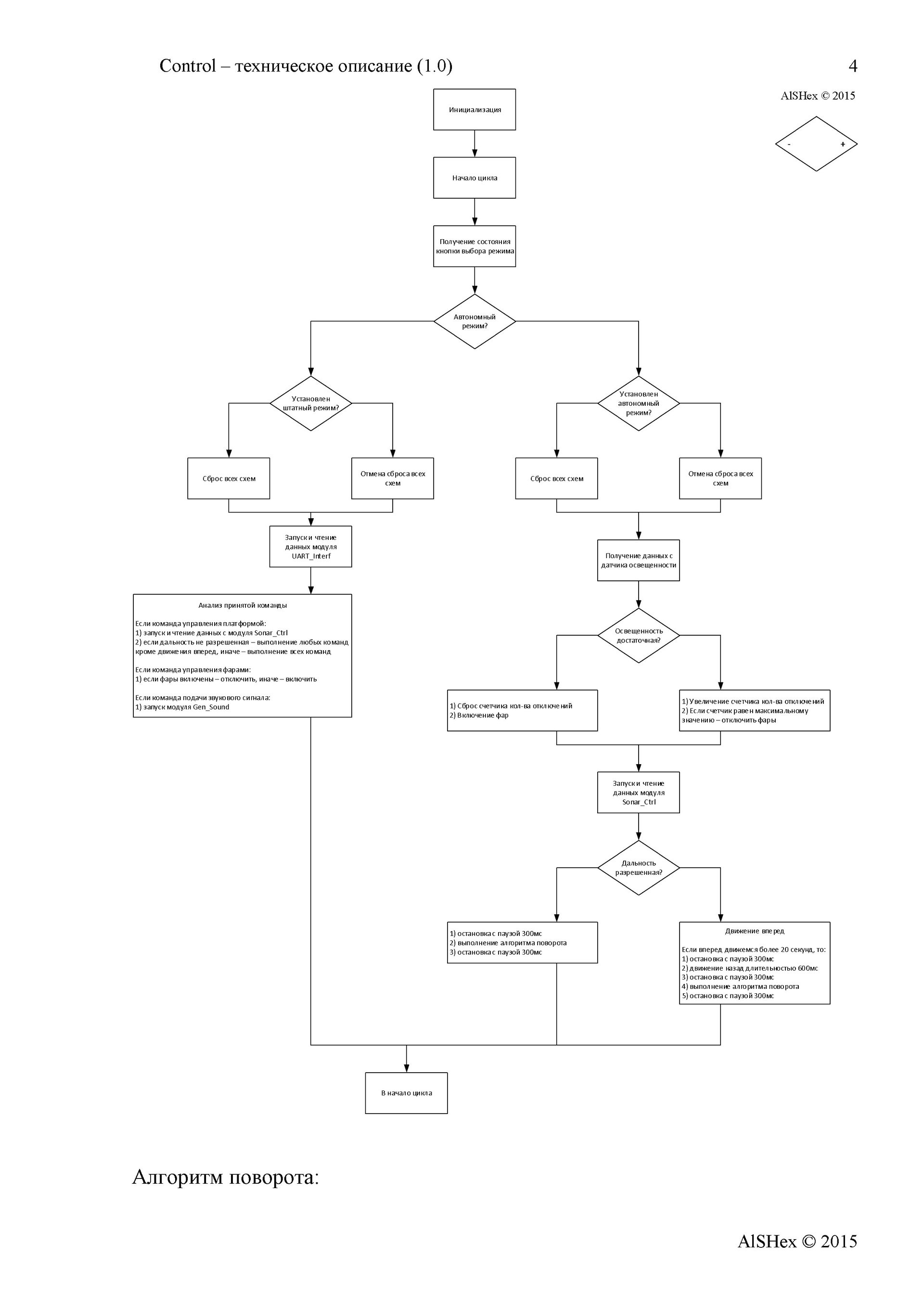
The command must be received by the interface module. It is he who must recognize that the incoming data makes sense, that it is not interference or the wrong command. When identifying a command, the module must inform the management module what kind of command it has come to us. The command control module will have to perform some actions — start moving, stop, “see” whether there are any obstacles ahead, turn on the lights or turn them off, and so on.
If the offline button is pressed, the control module will have to determine whether there are any obstacles ahead and move forward by issuing the appropriate command to the motor module, as well as take some action if there is an obstacle. The functions of directly controlling the end devices are partially delegated to other modules based on the level of complexity. The control module, in order to order the module to move engines forward, needs to know whether it is possible to move forward. In general, most likely, just like that, you will not receive data from an ultrasonic sensor - and why should we do this? We only know how to command - there is a sonar module for working with the sensor! Here we are requesting a report on the operational situation in front of the robot - can you go ahead?
The soldering iron happily and imperceptibly got out from under the rag, looking with interest at the outlet: I wonder how many volts there are - 110 or 220?
The fourth stage - creativity: detailed development
What and how to do it is clear. It is clear from what. It is clear exactly how it should and will look functional. It's time! It's time to start doing something! So many things have been read, viewed, appreciated, thought out, invented, rejected, painted. Eh ... there, a soldering iron lies not far away. Looking at us. Perplexed - it would seem to take it and solder, then what to do with garbage? We sigh and cover the soldering iron with a piece of paper: sleep for now, not everything is ready yet. It is not enough to understand how everything will look functional, you need to understand how everything will look structurally. It is necessary to maximally detail your understanding.
Communication unit
Practically everything was found out at the last stage. All clear. On the cyber-place forum, let's take a look at this topic and understand how to flash the TP-Link MR3020 router and configure it. Download the firmware for the router. We create files with a description of where what IP to enter, what and where to click. The only problem is that it is not clear which teams will be sent to the microcontroller.After sitting on the forum, reading and talking it becomes more and more understandable (thanks more to everyone who answered me and tried to help). We write all the commands in the same text file and mark which team is responsible for what. It turned out to be simple - when you press a button, for example, “forward,” a certain ASCII line of code is sent, and when you release the button, another command is issued - “stop” (which bytes are transmitted below).
Control block.
At the previous stages we determined what exactly will be connected to the control unit. The heart of the control unit is the Arduino nano. What it is?What are those bulbs responsible for and these connectors? What conclusions are connected feet from sonar? Anyway: how to communicate with the sonar?
We begin to study information on components. Fortunately, the library does not need to go in the presence of the Internet. We make for ourselves the technical descriptions of the components used. You can read on the Russian-language resources which board how it works and take notes. In order to understand how to connect and how to work with end devices, they create their own “datasheets”, in which everything is extremely brief, clear and understandable. It may be enough just to study the English-language datasheet from the manufacturer, but sometimes it happens that the language is Chinese or the datasheet itself is quite voluminous (there are 200 pages), so it’s reasonable to make your own brief notes.
Create for yourself a "help" on the microcontroller:
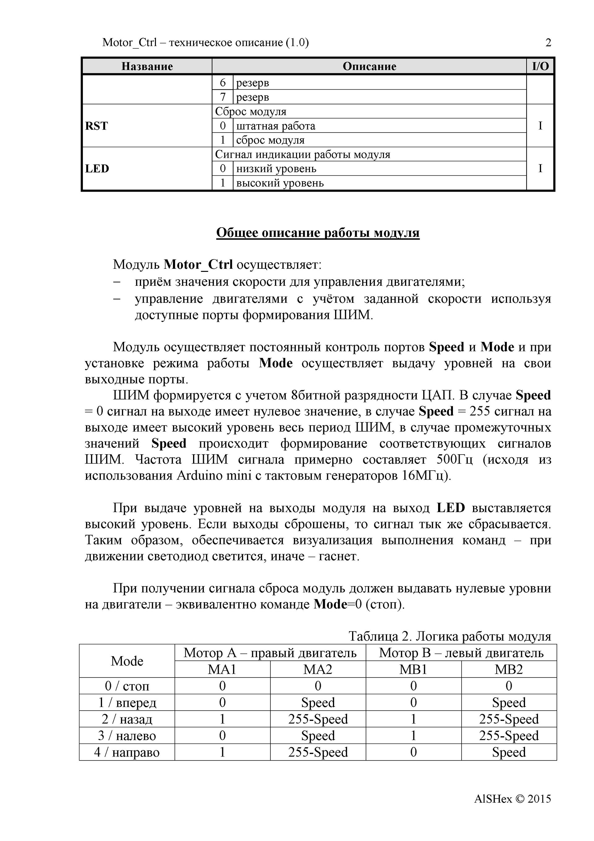
Then we understand how peripheral devices are connected and controlled. Engine Driver:
And ultrasonic sensor:
After all this understanding, a block diagram of the connection of software modules is drawn, which reflects the interaction with them and contains information about what and where is connected (to which legs of the microcontroller):

Drawing this scheme requires a good mental effort - after all, in fact, the framework is set, on which the code then falls. Here it is necessary to make a remark. The fact is that I am engaged in development on the FPGA, therefore, initially I painted the structure as I would for the FPGA. It should be understood that for SI-like programming the number of signals on the circuit is actually redundant. But on the other hand, we get a kind of platform independence - you can try everything on FPGAs, especially there are options available .
Let's read this diagram from left to right. The UART interface module will receive the data. If the data is a command, then it issues the control byte CTRL under the pulse SCTRL gate to the control module. The control module, having received a strobe, understands that a command has arrived, reads the CTRL input and executes the command. Let's say the team came "forward." A pulse signal Get_Dist is output to the output and data on the Dist input is expected. In principle, we are not prohibited from constantly issuing Get_Dist pulses, in this case we can simply remove the distance value from the Dist input port at the right time. Suppose everything is fine with the range - the obstacle is still far away, and you can ride with a breeze. The motor control module sends a signal to the Mode bus, indicating that it is necessary to move forward with the set Speed.When measuring the distance and when moving to the corresponding LEDs, a high level is also given (logical unit) to indicate the operation and understanding of what is happening with the system (it will be useful for debugging).
The modular scheme is there! In the head order! It is clear how and what. Now you just need to describe it - what each module should do and under what conditions.
A tail with a plug from a soldering iron fell out from under the edge of the sheet around the corner of the table. The leaf slipped a little and opened its face. The soldering iron looks with an expression that does not even require the gesture “twist the finger at the temple”: “TK writes himself to himself - what for heresy ... I was lucky with the owner, however,” he thought sadly, imperceptibly shaking his fork at the table.
Fifth stage - creation
Development is almost complete. All moments are clarified to the limit. It remains to create a miracle - from this heap of spare parts and a small stack of leaves with pictures, tablets, diagrams and diagrams to collect something, for which everything was started.
Grab a sad soldering iron and turn on the outlet. He begins to bask and hiss with pleasure in those moments when we clean the sting on the sponge. Flux with solder lead a friendly round dance on the table. The sun peeks out the window, highlighting the spot solder SMD resistor on the board. Life is good when you solder slowly!


The most fun and entertaining stage of development, which will not leave anyone indifferent. There is already something interesting, obvious to everyone. This stage contrasts with all the previous ones, since drawing some pictures with tablets, not only is it not interesting for the observer to sincerely understand how something can come of it. And then ... it's so great when your first robot will drive its first centimeter on the table and respectfully stop from the edge exactly 20 centimeters just because you have blocked the edge of the table with your palm. A clever tvaryushka turned out - he understands that he cannot continue!


At this stage, we assemble the entire mechanical structure, solder the wires, and program the microcontroller. We are testing what happened. We do not understand. We think.We rule the TK, as in reality it turns out, perhaps, quite differently from what is written and invented! We return again to the assembly. We are testing. We do not understand. Do not lose heart. We poke a multimeter and replace dead batteries. We are happy ...


Strictly speaking, at the end of this stage a list should be formed, which together with the above documentation would ensure repeatability of the result. I mentioned the large components above, however, when placing an order, I also asked to put the necessary “distribution”: a power switch, a connector for connecting the battery compartment, a 2.54-mm connector strip ...
In addition, consumables were used in the work - wires, solder, flux, as well as tools. If there are any technological nuances, attention should also be focused on them.

I wrote the program twice.
The first time was written as it was written. I actively read the site arduino.ru I did not write the program anymore, but I understood the syntax, recalled C and constantly used to swear at the sequence of program code execution (I got used to the parallel execution of the code, when all the computational blocks and not only one line is processed).
The second time I approached the organization of the program rigidly structurally. This was not always justified, but if the original style was set, it should be adhered to. The meaning is ... repetition in the code structure of the software models drawn above. In the code, we first declare all the variables and set up tuning constants. Then follows the initialization block “void setup”. And then follows the main “void loop” cycle, the task of which is to continuously poll modules. Each module has its own input and output variables that affect its operation. In the main loop, these variables are managed.
The polled button sets the operation modes of all modules. If a command came through the interface, it is transmitted to other control modules, if the offline mode is not activated. At first I had only two modules - motor and light controls. Then a sound shaping module appeared, which I did not have time to do. This is precisely what the built-in structure affected - it is simple and clear to add / exclude modules: a block in variable declarations, a line in the initialization, a line in the main loop, and the code of the module itself. The module for determining the distance and the module implementing the turn algorithm are called from other modules as necessary.
The sixth stage is the comprehension of creation.
What did we want to do?
Let's get a look:
In general, it seems to be nothing. Rides Stops. Is spinning. But ... not so good. The robot goes quite cheerfully without the “second floor”, but when installing the second one it’s obviously “boring”. In addition, he constantly takes to the left, hinting that he alone is very bad in life, and since he did it, it would be nice to attend to this very ... variety of species.
Summing up, you can honestly admit that there is much to develop.
1) The robot always takes to the left with a rectilinear motion. The stronger the discharge of the power source, the greater the deviation. Obviously, this is due to the variation of the parameters of the engines, possibly due to the different work of the channels of the driver of the engines. To eliminate this behavior of the robot, it is necessary to connect optical encoders and, receiving information from them, adjust the algorithm of the engine control module when moving forward or backward. In addition, for the power source, you must have an integrated voltage regulator, for example, you can transfer power to a pair of Li-ION cells using a buck converter.
2) The robot often does not see the object in front. This is due to the narrow viewing angle of the ultrasonic distance meter. It is obvious that the accuracy and reliability of determining the distance to objects can be improved by installing two or three ultrasonic sensors. To determine the distance, the sensors are interrogated sequentially with short pauses to eliminate the effect of the reflections of the ultrasonic signals on each other.
3) A couple of times on the firmware version 1.0 there was a situation of hanging up the rotation algorithm - the robot was constantly spinning and did not move forward, even if there was no obstacle ahead. If the robot is forced to hold in a free direction, then after a while it began to work normally. To eliminate such situations, it is necessary to expand the criteria for self-diagnosis of the behavior of the robot with its forced re-initialization in case of problems. To avoid freezing MK, you must use WatchDog.
4) In case of remote control, a situation often arises when, after releasing the button on the keyboard that specifies the movement, the robot did not stop. Then it was necessary to quickly press and release any movement button. Perhaps the “stop” command was lost in the receiving buffer, perhaps the command was not issued from the router. To avoid such situations, a “stop” command must be issued from the router several times in a row when the movement button is released.
5) When creating firmware for MK, the program specifies a consistent execution of the program. In order to work out the “forward” command, you need to sequentially interrogate the interface modules, determine the range, control, and then call the motion module. With such a survey, the range determination module introduces a delay of up to fifty milliseconds, slowing down the decision on the incoming team. In the case of excessive expansion of the functionality or the appearance of additional range modules, the delay may become unacceptable. There is no such problem in the FPGA - all the blocks at a time are working in parallel, i.e. It is permissible to receive a command at one time, process the range and output it to the LED, and also perform a bunch of other operations. In MC, parallel execution of even unrelated functions with each other is impossible, or it is necessary to constantly use interrupt on external events, which is not always convenient. However, the development of firmware for the FPGA is, essentially, more labor-intensive work, which requires certain qualifications, since Virtually any programmer can write C code, and writing code on VHDL / Verilog requires an understanding of how the chip logic works.
6) With remote control, the picture from the onboard camera changes too much, making orientation in space difficult. To reduce this effect, it is necessary to apply anti-aliasing and / or reduction of the display window.
7) In the process of testing revealed an unsuccessful design of the mechanical part. When fully loaded (platform + “second floor”), the dynamics of the platform decrease, you can hear squeaks when cornering. Perhaps the situation can be corrected by raising the supply voltage. In addition, the rear wheel often gets stuck when cornering and lubrication of the ball bearings does not help because of the unsuccessful design.
8) With manual control at maximum speed while moving forward, if necessary, stopping and fast backward movement, the robot could sharply lean forward, while the rear pivot point was taken off the ground.
And how should we be now?
1) The implementation of the issuance of a sound signal - the development of a generator of sound signals with a certain frequency.
2) Aligning wheel speed in straight-line motion using optical sensors and optical encoders for wheels.
3) The implementation of automatic on / off headlights using the sensor light.
4) Improving the reliability of determining the distance to the objects in front by increasing the ultrasonic sensors to three.
5) Power supply based on two Li-Ion batteries, size 18650, and an integral voltage regulator.
6) Disassemble and lubricate the gear motors with silicone grease to eliminate squeaks.
7) Assess the increase in supply voltage to 6.0-7.5V. In this case, take into account that you have to recalculate and re-solder resistors for LEDs to prevent the maximum output current of the MK output from being exceeded.
8) With an abrupt change of state (starting or stopping) to realize a smooth change in speed, the change function can be linear or exponential.
Seventh stage - development
go to "Second Stage"
Well, here, we got to the finale of the whole story.
I successfully demonstrated the robot and passed it along with, so to say, supporting documentation, as well as a description of the identified deficiencies and ways to eliminate them. In my opinion, acquaintance with these technical descriptions and technical tasks should make a correct understanding of the operation of electronic devices "inside", as well as remove the vast majority of "thin" technical issues. It seems that everyone was happy.
Unfortunately, I do not always have enough free time to seriously participate in the development of the company Endurance. As far as I know, the company is looking for interested and moderately independent developers, and if you are not only interested in this topic, but also have some experience, opportunities and a desire to participate in robot building, then they will surely welcome you there.
Of course, the use of a robot in this performance is seen in an ironic light from the point of view of some industrial problems. However, this platform may be useful. I think it would be nice for me to have such a robot at the cottage for the purposes of remote monitoring. If you install servos on it that allow you to rotate a video camera, think over the power supply system, then I could at any time inspect the situation in the house. And if you make a check on the windowsills to the windows (yes, at least just put the boards, making an inclined plane), then outside the house.
If the batteries are replaced with Li-ION batteries, they can be charged without any problems, because similar controllers are available in finished form. In the first version of such a robot, after inspection, it can be simply customized to the charging station manually, and it will connect the contactors using, for example, miniature electromagnets (offhand: the robot can switch to mains supply at the time of switching and the batteries will be isolated from wiring and charging autonomously). In the second version of the robot, you can learn how to do it yourself - drove to the charging station and pressed the “parking” button (offhand: you can draw some bright figure in the center of the parking target, the robot will be guided by using the color detection sensor, and at night everything will be highlighted headlights).
Good luck in robotics!
Do not be afraid to start.
Even more enthusiastic, choosing an interesting and, at first glance, simple option, go into action and, often copying, make their first robot. This is a strong-willed and very significant decision - the main thing is to start at least do something yourself! In the process of manufacturing, there is a lot of technological stumbles up to the point that it turns out for ordering / buying some items, you need to find out how exactly it is called. And yet - the connectors are not soldered normally - and how does everything work with a one-touch video? The creation process is often delayed, but the persistent beginner robotics somehow finishes the result to some meaningful first launch at least “in a straight line”.
')
Then, when the robot is finished, there comes an understanding of why everything is being done this way and in that sequence. The creation process can already be somehow realized, formalized, painted. It is from this moment that the development of the model of the next, second generation begins.
Yes, I also read articles with interest before. And now I read! I especially like articles about copters: from the ground, yes to heaven! However, to be honest, they caused only thoughts in me. Moreover, it was necessary to understand programming, and the last time I worked with C at the institute, everything was completely forgotten. I know what Arduino is, but I have never seen it live. And so on. I have a technical education, I deal with DSP on FPGA. Technically, there are no obstacles for me to take and figure out, but ... in fact, I do all this at work and I have all this business there, as they say, "above the roof." As a result, I needed some kind of good incentive to somehow start doing this. Stimulus appeared when it became necessary for someone else: the truth is that real creation is when you give to others.
My good friend, who is one of the founders of Endurance , a young (one might say freshly baked) company, knowing the nature of my work, turned to me on a number of technical issues. It turned out that the guys have developers in the USA and have already presented their prototype of the super-cheap (phone + plastic platform with wheels on the Arduin - it seems to be cheaper and nowhere) a telepresence robot. But they wanted not just to do one marketing and business in the style of “bought there - sold here”, but they wanted to immerse themselves in more detail into a technical topic and even plan to develop their own model (even if equivalent in principle and functionality), but here in Russia, in order to obtain not only the finished result, but also understandable by the technology of its manufacture. Such is the premise of participation in this matter of your humble servant (I hint at myself).
At first, I also read articles, looked where they buy and how they do it. But there was no single picture. It seems that, in general, everything is clear, but at the same time not everything. It is not clear how to control from a computer, how to deliver video to a computer. Moreover, I am not a softphone and I would not like to “dig out” this, soft, theme from scratch, although it would be interesting, of course; so I somehow successfully satisfied all my needs with the AutoIt scripting language. As a result of the search, I found two key resources that have become key for me: the online store carduino and the cyber-place forum. The store could buy all the necessary components - all in one place.
Prices, compared with ebay or ali, of course, wild, but the main thing was not the case - you could buy a platform and the necessary body kit for it, as well as all small things. And it was convenient to pick up / order. At the forum in the section "Do it yourself" \ "Robotics" and "Do it yourself" \ "CyberWrt" you can learn general information, as well as how to organize a detailed computer connection with the robot via Wi-Fi. Ten years of experience in the specialty made me feel, and instead of immediately starting to copy, twisting or programming something, I picked up a pencil and paper ...
What does “develop” mean? It is clear what “make a robot” means - you take it and ... you do it! And how to “develop” it?
Below I tried to describe the process, namely, development, and not the creation of a robot. The creation of a robot, as a construction, is initially intuitive and understandable. As the creation is screwed this - this, this - this. Ponakrutil so - and suddenly it turned out that the second part, it is necessary to fasten otherwise, then the eighth part will stand up like a glove, you just need to move the wiring from the batteries to the left closer to the fifth part, and in order not to dangle, it is better to attach to the fourth, slightly turning them as there will be the tenth part there. Sheer creativity. And let's try for an adult: first we will think about what we will do, and then we will do it :)
So, what will be discussed in this article. I decided not to write about how I did the robot, there are a lot of such articles and there is no sense in the appearance of another one. I’m certainly not the first, or even the tenth, who on the purchase platform, having mounted the sensors, made the toy to the delight of myself and others. I decided to try, so to speak, to state my technology of thinking. I tried to convey to readers not just the fact that it is not so difficult to make a robot, but to explain the methodology by which you can take and try to make your robot from scratch, and the beginning of robotics will be clear and understandable the steps of creation initially, rather than opening advancement into the unknown.
Imagine a person who has never worked on robotics. He has a friend, a soldering iron, a multimeter and any hand tools such as nippers, screwdrivers and others. Introduced yourself? Fine! Go…
The first stage - understanding
What do we want to do? And why is it necessary?
For me, this issue was initially resolved for me - I need to make a machine with a video camera that could connect via Wi-Fi or the Internet to a computer, on the computer I would see the picture from the machine and control it, causing it to move. It seems to be understandable, but somehow boring and something is missing. Remote control - is it some kind of robot? Robot? What is a robot? A robot is some kind of autonomous thing that does the work itself. How to apply it for this task? And let the machine will drive itself! As such, the formulation of the problem is not - well, let him go as he pleases. However, if she drives as she pleases, she will collide with objects. This is somehow wrong, wrong. So, the machine should be able to see ahead of itself and go around obstacles, preventing a collision. How can I do that? You can process the data from the camcorder. Uh-uh ... somehow it is not clear how to approach this at all. Probably it is not easy. What else do we have? Sold all sorts of infrared and laser distance meters! You can buy this and somehow get the distance from it. This is crazy, but there is something in it ...
Based on thinking, the idea is born, the concept of the device. The result of reflection should be presented in general terms thesis and briefly, concentrating the essence. You need to get a device that:
- is able to move on the surface according to the operator's commands, broadcasting video to him in front of himself;
- has an autonomous mode of "existence": can independently move in an arbitrary direction;
- controls the situation in front of him;
- in case of detection in front of some object, it does not allow itself to collide with it, ignoring the operator’s commands, or changes the direction of movement in the autonomous mode.
It seems to have decided on the goal. We take a soldering iron and arrange it on the table. You can wrap in a rag - it will be softer, more comfortable. Let him get used to the situation.
The second stage - the study of reality
After we decided on the basic functionality and it became clear what needs to be done, the question arises: how to do it, what will it look like?
You can take the hammer in your hands and tell your surroundings with a stern look, categorically: cover from the table, castors from chairs, a rubber band from underwear, a pair of Chinese chopsticks, 20 centimeters of cloth from the curtains, sandals from sandals, a laptop disassembled for parts - everything surrender to me in the name of progress! So that there are no unnecessary questions to the voice, you can give shades of threat and spiritualization at the same time. However, I propose a more efficient method: a tool created by people called the Internet is ideal for this purpose. We type the word "Robot do it yourself" in the search engine that your religion allows you to use, and start reading, watching, listening and understanding. This stage can last much longer than the previous one, since it is much easier to think of something to do than to figure out how to do it. Moreover, in passing, you can still find out so much interesting!
So, the result of this stage should be a more detailed abstract list, which will determine the form of what we came up with at the last stage. Our device will look like this:
- a three-wheeled platform with two engines: two driving wheels, the third - as a support;
- powered by AA batteries (1.2-1.3V x 4 = approximately 5 volts - just suitable for engines);
- the device will be controlled by the Arduino Nano microcontroller (motor control - through the driver of the engines, the microcontroller can be powered from 5V);
- the range will be determined using an ultrasonic sensor (5V power supply);
- the flashed router (5V power) will work as an access point, connecting to which you can connect to the web server and issue commands to the microcontroller, while we will have a picture from the webcam connected to the router;
- two switches are installed on the device: ON / OFF power and ON / OFF standalone mode - from this point on, no devices, since it can work autonomously - it means the robot;
- the robot is equipped with an LED that will light up when an obstacle is detected;
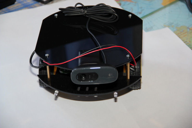
- on the robot there will be two bright white LEDs on the front - lights - why not: when it’s dark, the robot shouldn’t be scared, and with a bright light it’s always more cheerful, the main thing is not to look back again - the video camera will be sent only forward;
- the robot will have a webcam installed that will be connected to the router.
This appearance we represent is based on the ideas that we received by studying the market of components for robots. There is no detailed presentation of the robot to the screw - only common features, however, they allow us to imagine what the result will be. In general, we come to the conclusion that everything can be bought in the carduino store, as well as to communicate with the robot using the router and setting it up in the same way as indicated on the cyber-place forum. Until you understood the intricacies of connecting individual components and did not understand how to program the router. But they realized that the individual components can be connected to each other (electrically and informationally), and also determined, at a minimum, the structure and appearance.
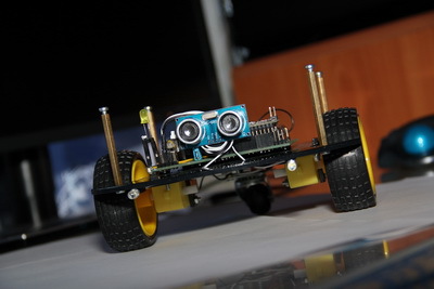
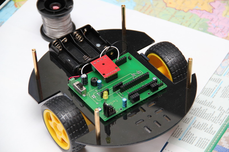
Robot components
Platform with wheels, engines and fasteners:

Electronics fee:

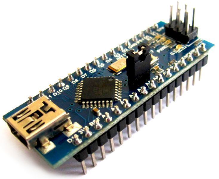
Microcontroller Carduino Nano v.7:
Ultrasonic Sensor HC-SR04:

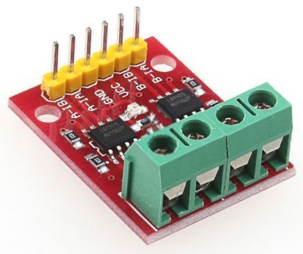
Driver for engine management:
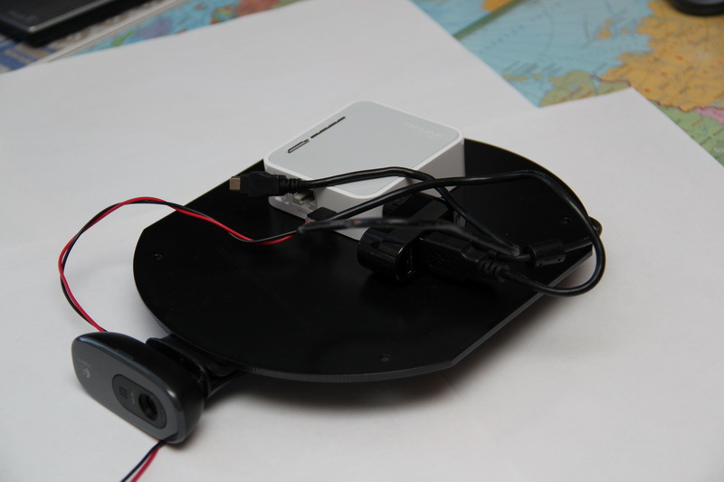
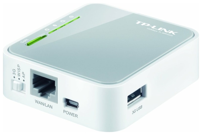
TP-Link MR3020 Router:
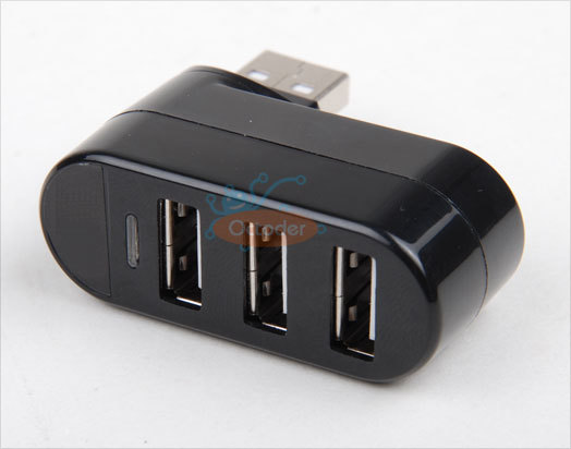
Hub (compact and miniature hub of an unknown model):
Webcam (Logitech C270):

Electronics fee:
Microcontroller Carduino Nano v.7:
Ultrasonic Sensor HC-SR04:
Driver for engine management:
TP-Link MR3020 Router:
Hub (compact and miniature hub of an unknown model):
Webcam (Logitech C270):
The soldering iron lies on the table and looks interested at the pictures above. Interest is clear - to solder it all to him!
The third stage - creativity: general development
So much time was spent, but the result is not yet visible! The result is only in our heads in the form of images and thoughts. Maybe it is worth somehow to materialize these thoughts? How the appearance of the robot will look like is already clear. Also defined a set of components. How will it connect? How will all this communicate with each other? The robot - it's not a light bulb - clicked the switch and it caught fire. Then he clicked the tumbler, the power went on - and then what? And here, dear readers, the development begins to branch into three components: design, electrical and software.
We will not have a full-scale engineering development, as we use everything completely ready. All the visible design work will be in the successful gluing of individual boxes on double-sided tape and screwing the bolts in specially designated areas. On a good bill, of course, there must be an assembly drawing of those components that are. But, if we didn’t have a platform or foundation, then we should estimate the sizes of all components to be installed, calculate the dimensions and understand how much the base board will be made of, and how other components of the robot will be attached to it, and so on. But, everything is simple here, the pictures of the final type of robot perform the role of an assembly drawing, therefore this direction of development in this article is not considered at all.
After sitting and painting you can come to the following functional robot view:
I apologize in advance for the quality of the pictures. I got a lot of pictures, but I didn’t want to inflate the traffic under the cut, so I came to some compromise between quality and volume, which means that weighed a little, but was readable and understandable.
What do we see in the picture?
Our robot will consist of two independent parts: a communication unit and a control unit. The communication unit communicates with the external operator, receives commands from it, and issues them to the control unit. The control unit, taking commands, executes them. That is, we divided the management into two levels - low-level (platform control, interaction with sensors) and high-level (interaction with the operator and command control of the low-level part). The management task was divided into two parts that can be solved separately: first, deal with the moving platform in the form of an Arduino microcontroller, then with the connection in the form of a reconfigured router.
Communication unit
1) Elektkrotekhnika. Here, it seems, in general, everything is clear: the camera gives video and sound and connects via a hub to the router. To him through the hub and connects Arduino. There is little wisdom to plug the cable into the USB connector, the probability of doing it wrong, or vice versa, is quite small. However, there is enough of this probability for some, but this is not about us !!! We look, where we interpose, if we don’t climb, we just press it harder - it should fit, this is USB!
2) Programming. There is no development, as already used firmware is used for the router and ready-made modules for the robot. The interface protocol with the control unit has already been identified for us - we also just need to figure it out. How exactly to flash and what exactly to set up there - let's see later.
Control block.
1) Electrical engineering. It seems, too, everything is clear. We have a motherboard on which everything is unsoldered. It will be necessary only to figure out where the sensors are connected to the Arduino and at the same time never mess up the extra work, confusing the ground with power. In terms of connectivity, there seems to be no particular problems. True, you don’t immediately figure out where on the board what is connected, but after looking at the works of the masters , and also, having found the picture below, everything falls into place. How is it and what is divorced - then we will understand, especially since nobody canceled the file rule : if we do something, we will refine it!
2) Programming. And here is the problem. How and what should be done there. Here came the team. What to do? We take again a pencil with a piece of paper and draw. As a result, you can get the following functional software scheme (platforms only):
Turned out the next squares. But now it is purely software modules. Some materialization of that which cannot be touched and touched, but it is, as the robot moves on the basis of the logic of this level of abstraction.
The command must be received by the interface module. It is he who must recognize that the incoming data makes sense, that it is not interference or the wrong command. When identifying a command, the module must inform the management module what kind of command it has come to us. The command control module will have to perform some actions — start moving, stop, “see” whether there are any obstacles ahead, turn on the lights or turn them off, and so on.
If the offline button is pressed, the control module will have to determine whether there are any obstacles ahead and move forward by issuing the appropriate command to the motor module, as well as take some action if there is an obstacle. The functions of directly controlling the end devices are partially delegated to other modules based on the level of complexity. The control module, in order to order the module to move engines forward, needs to know whether it is possible to move forward. In general, most likely, just like that, you will not receive data from an ultrasonic sensor - and why should we do this? We only know how to command - there is a sonar module for working with the sensor! Here we are requesting a report on the operational situation in front of the robot - can you go ahead?
The soldering iron happily and imperceptibly got out from under the rag, looking with interest at the outlet: I wonder how many volts there are - 110 or 220?
The fourth stage - creativity: detailed development
What and how to do it is clear. It is clear from what. It is clear exactly how it should and will look functional. It's time! It's time to start doing something! So many things have been read, viewed, appreciated, thought out, invented, rejected, painted. Eh ... there, a soldering iron lies not far away. Looking at us. Perplexed - it would seem to take it and solder, then what to do with garbage? We sigh and cover the soldering iron with a piece of paper: sleep for now, not everything is ready yet. It is not enough to understand how everything will look functional, you need to understand how everything will look structurally. It is necessary to maximally detail your understanding.
Communication unit
Practically everything was found out at the last stage. All clear. On the cyber-place forum, let's take a look at this topic and understand how to flash the TP-Link MR3020 router and configure it. Download the firmware for the router. We create files with a description of where what IP to enter, what and where to click. The only problem is that it is not clear which teams will be sent to the microcontroller.After sitting on the forum, reading and talking it becomes more and more understandable (thanks more to everyone who answered me and tried to help). We write all the commands in the same text file and mark which team is responsible for what. It turned out to be simple - when you press a button, for example, “forward,” a certain ASCII line of code is sent, and when you release the button, another command is issued - “stop” (which bytes are transmitted below).
Control block.
At the previous stages we determined what exactly will be connected to the control unit. The heart of the control unit is the Arduino nano. What it is?What are those bulbs responsible for and these connectors? What conclusions are connected feet from sonar? Anyway: how to communicate with the sonar?
We begin to study information on components. Fortunately, the library does not need to go in the presence of the Internet. We make for ourselves the technical descriptions of the components used. You can read on the Russian-language resources which board how it works and take notes. In order to understand how to connect and how to work with end devices, they create their own “datasheets”, in which everything is extremely brief, clear and understandable. It may be enough just to study the English-language datasheet from the manufacturer, but sometimes it happens that the language is Chinese or the datasheet itself is quite voluminous (there are 200 pages), so it’s reasonable to make your own brief notes.
Create for yourself a "help" on the microcontroller:
Carduino Nano v.7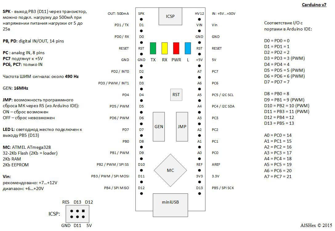
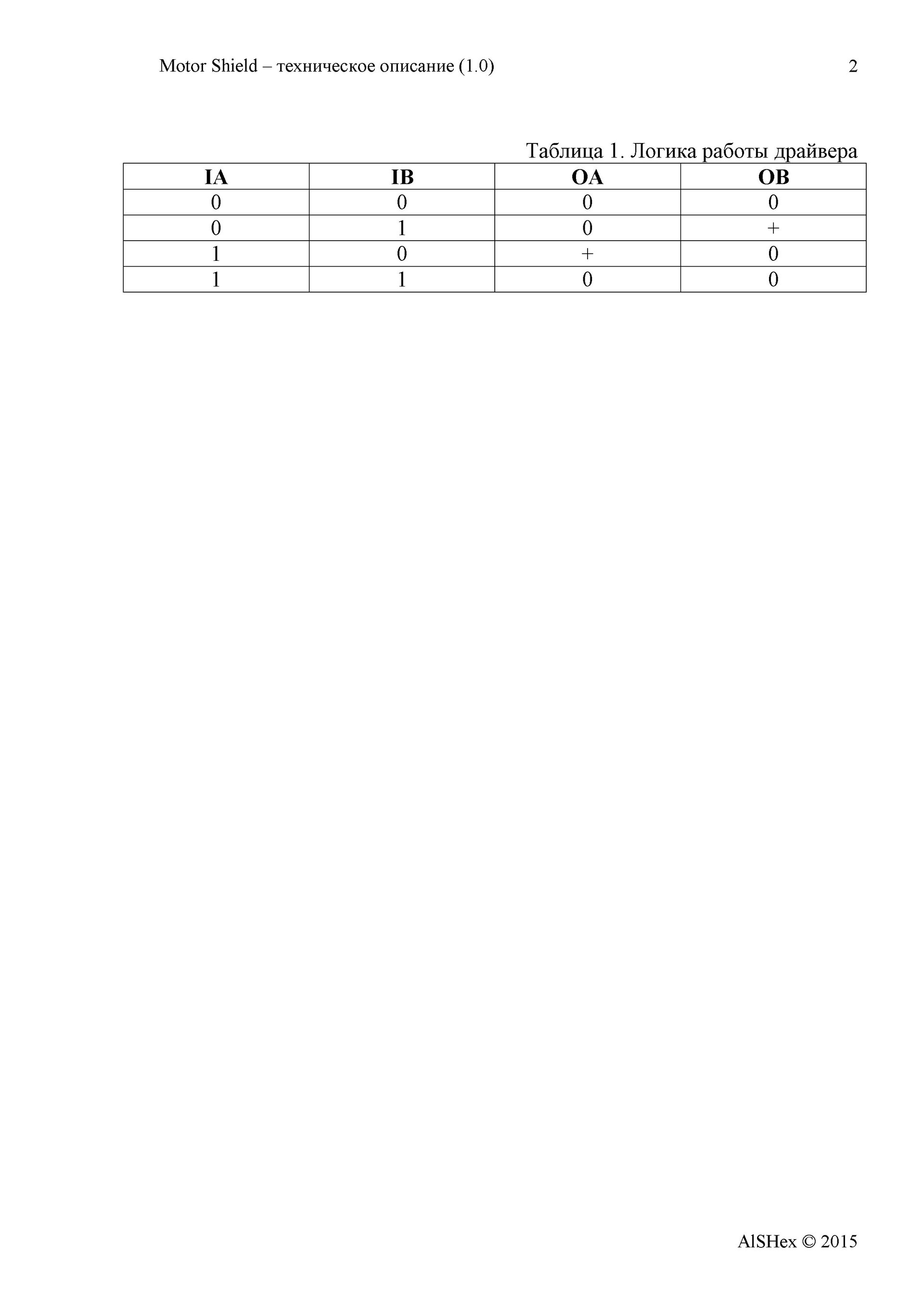
Then we understand how peripheral devices are connected and controlled. Engine Driver:
L9110S chip driver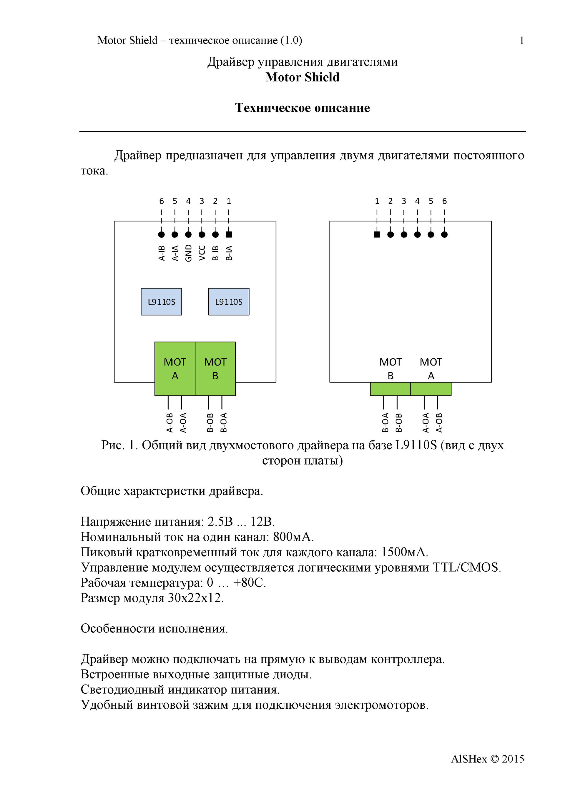
And ultrasonic sensor:
Sonar HC-SR04

After all this understanding, a block diagram of the connection of software modules is drawn, which reflects the interaction with them and contains information about what and where is connected (to which legs of the microcontroller):
Drawing this scheme requires a good mental effort - after all, in fact, the framework is set, on which the code then falls. Here it is necessary to make a remark. The fact is that I am engaged in development on the FPGA, therefore, initially I painted the structure as I would for the FPGA. It should be understood that for SI-like programming the number of signals on the circuit is actually redundant. But on the other hand, we get a kind of platform independence - you can try everything on FPGAs, especially there are options available .
Let's read this diagram from left to right. The UART interface module will receive the data. If the data is a command, then it issues the control byte CTRL under the pulse SCTRL gate to the control module. The control module, having received a strobe, understands that a command has arrived, reads the CTRL input and executes the command. Let's say the team came "forward." A pulse signal Get_Dist is output to the output and data on the Dist input is expected. In principle, we are not prohibited from constantly issuing Get_Dist pulses, in this case we can simply remove the distance value from the Dist input port at the right time. Suppose everything is fine with the range - the obstacle is still far away, and you can ride with a breeze. The motor control module sends a signal to the Mode bus, indicating that it is necessary to move forward with the set Speed.When measuring the distance and when moving to the corresponding LEDs, a high level is also given (logical unit) to indicate the operation and understanding of what is happening with the system (it will be useful for debugging).
The modular scheme is there! In the head order! It is clear how and what. Now you just need to describe it - what each module should do and under what conditions.
Interface module: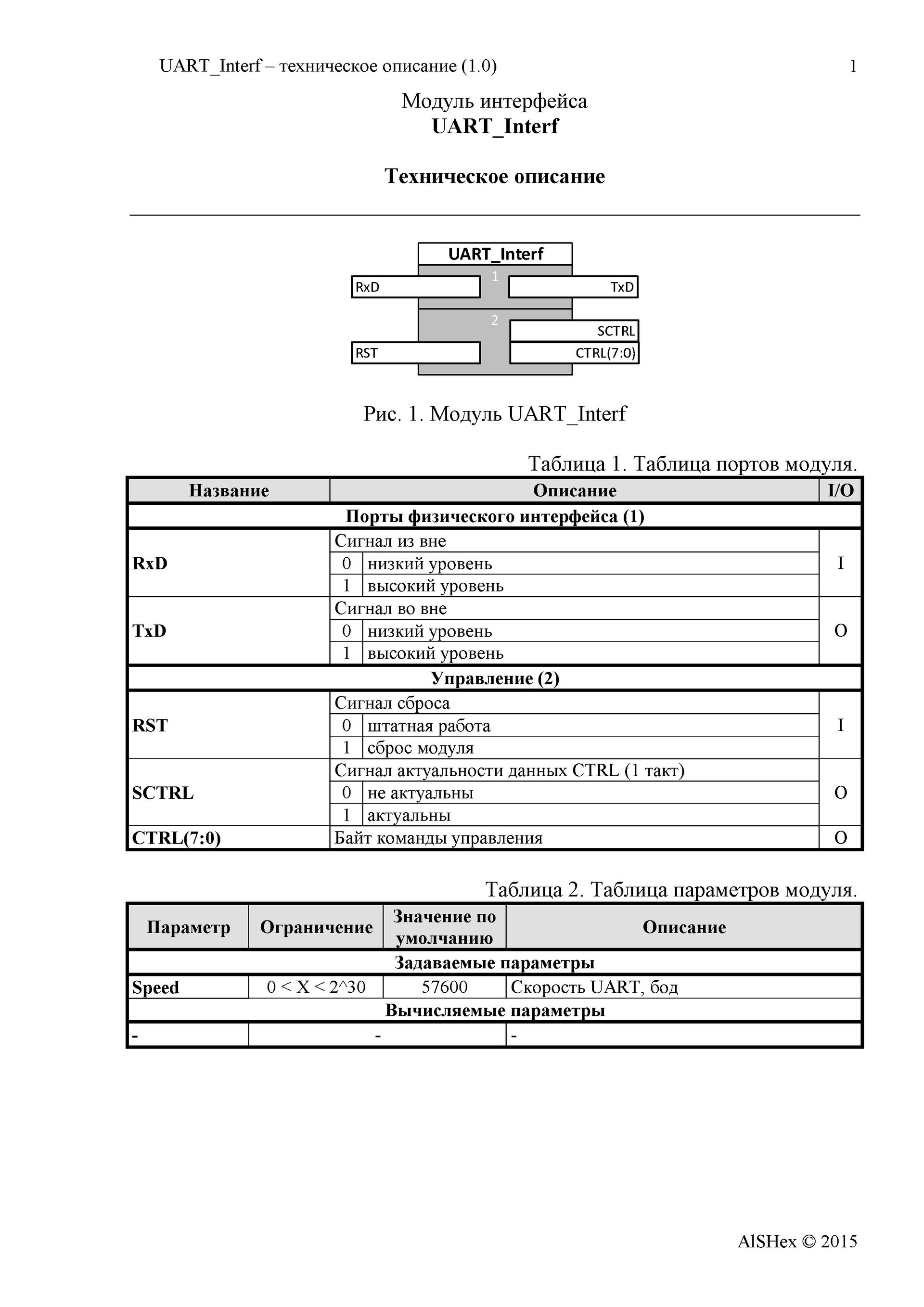


Control Module:


Range measurement module:


Motor control module:
A tail with a plug from a soldering iron fell out from under the edge of the sheet around the corner of the table. The leaf slipped a little and opened its face. The soldering iron looks with an expression that does not even require the gesture “twist the finger at the temple”: “TK writes himself to himself - what for heresy ... I was lucky with the owner, however,” he thought sadly, imperceptibly shaking his fork at the table.
Fifth stage - creation
Development is almost complete. All moments are clarified to the limit. It remains to create a miracle - from this heap of spare parts and a small stack of leaves with pictures, tablets, diagrams and diagrams to collect something, for which everything was started.
Grab a sad soldering iron and turn on the outlet. He begins to bask and hiss with pleasure in those moments when we clean the sting on the sponge. Flux with solder lead a friendly round dance on the table. The sun peeks out the window, highlighting the spot solder SMD resistor on the board. Life is good when you solder slowly!
The most fun and entertaining stage of development, which will not leave anyone indifferent. There is already something interesting, obvious to everyone. This stage contrasts with all the previous ones, since drawing some pictures with tablets, not only is it not interesting for the observer to sincerely understand how something can come of it. And then ... it's so great when your first robot will drive its first centimeter on the table and respectfully stop from the edge exactly 20 centimeters just because you have blocked the edge of the table with your palm. A clever tvaryushka turned out - he understands that he cannot continue!
At this stage, we assemble the entire mechanical structure, solder the wires, and program the microcontroller. We are testing what happened. We do not understand. We think.We rule the TK, as in reality it turns out, perhaps, quite differently from what is written and invented! We return again to the assembly. We are testing. We do not understand. Do not lose heart. We poke a multimeter and replace dead batteries. We are happy ...
Strictly speaking, at the end of this stage a list should be formed, which together with the above documentation would ensure repeatability of the result. I mentioned the large components above, however, when placing an order, I also asked to put the necessary “distribution”: a power switch, a connector for connecting the battery compartment, a 2.54-mm connector strip ...
In addition, consumables were used in the work - wires, solder, flux, as well as tools. If there are any technological nuances, attention should also be focused on them.
I wrote the program twice.
The first time was written as it was written. I actively read the site arduino.ru I did not write the program anymore, but I understood the syntax, recalled C and constantly used to swear at the sequence of program code execution (I got used to the parallel execution of the code, when all the computational blocks and not only one line is processed).
The second time I approached the organization of the program rigidly structurally. This was not always justified, but if the original style was set, it should be adhered to. The meaning is ... repetition in the code structure of the software models drawn above. In the code, we first declare all the variables and set up tuning constants. Then follows the initialization block “void setup”. And then follows the main “void loop” cycle, the task of which is to continuously poll modules. Each module has its own input and output variables that affect its operation. In the main loop, these variables are managed.
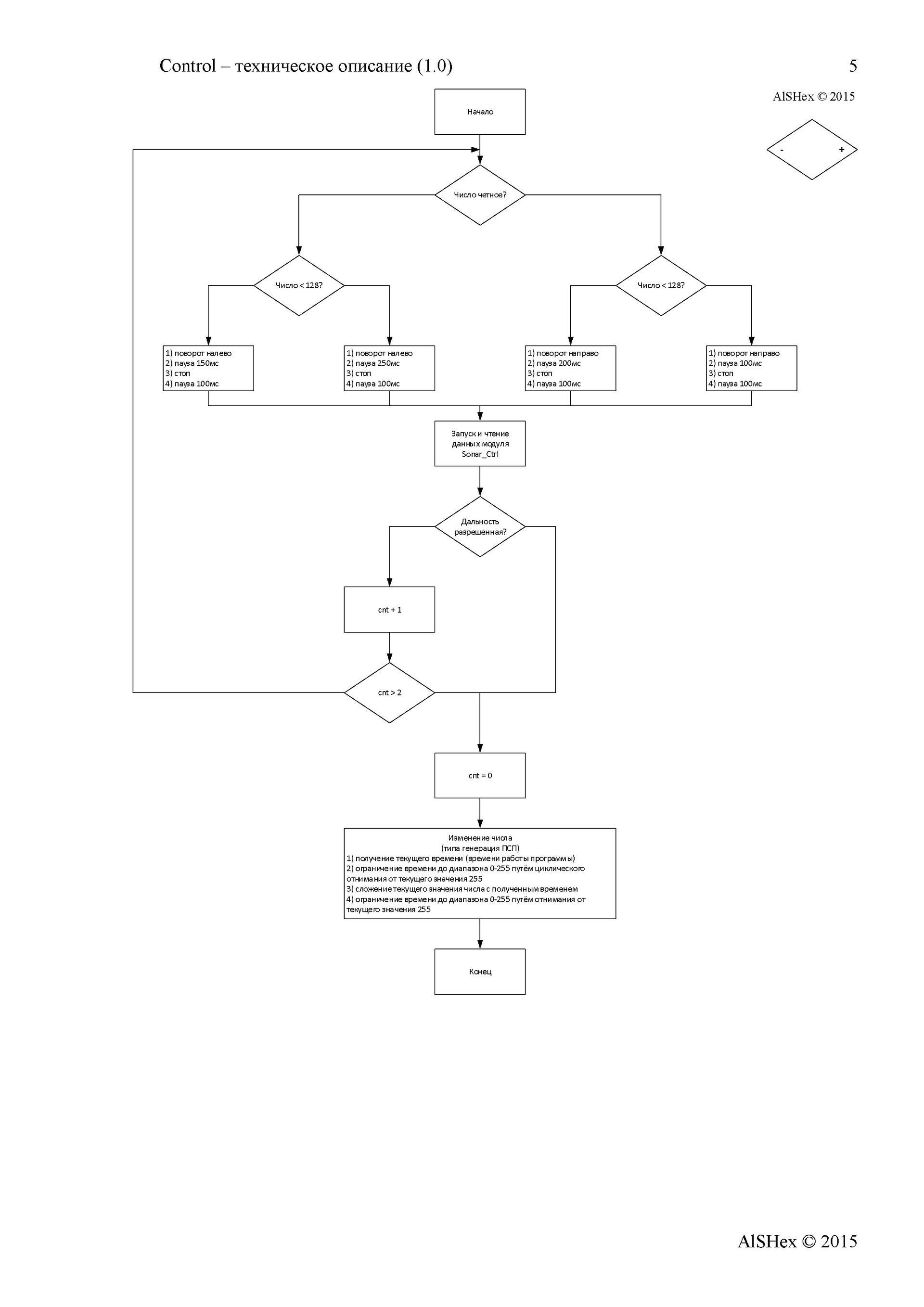
The polled button sets the operation modes of all modules. If a command came through the interface, it is transmitted to other control modules, if the offline mode is not activated. At first I had only two modules - motor and light controls. Then a sound shaping module appeared, which I did not have time to do. This is precisely what the built-in structure affected - it is simple and clear to add / exclude modules: a block in variable declarations, a line in the initialization, a line in the main loop, and the code of the module itself. The module for determining the distance and the module implementing the turn algorithm are called from other modules as necessary.
Text of the program
////////////////////////////////////////////////////////////////////////////////////////////////////////// // Robot Platform RASH 1 AlSHex // 1.0 // // Create: 23/03/2015 // Modification: 11/04/2015 // // Description: RASH 1 // ////////////////////////////////////////////////////////////////////////////////////////////////////////// // const int LEDtech = 13; // const int LEDdist = 3; // const int Sonar_t = 14; // const int Sonar_r = 15; // const int Mode = 16; // - : =0 - ; 1= const int MB1 = 4; // - digital const int MB2 = 5; // - pwm const int MA1 = 6; // - pwm const int MA2 = 7; // - digital const int HDL = 17; // const int SPK = 11; // //const int LGHT = ; // // const long UART_Speed = 9600; // UART // const int D1 = 20; // const int D2 = 110; const float A = 2.5; const float B = 305; // const byte Byte_forward = byte('W'); //: const byte Byte_back = byte('S'); //: const byte Byte_left = byte('A'); //: const byte Byte_right = byte('D'); //: const byte Byte_stop = byte('x'); //: const byte Byte_sound = byte('C'); //: / const byte Byte_light = byte('V'); //: const int Dist_min = 40; // , [] const int Cycle_lightoff = 1000; //- const int Speed_default = 255; // , , // const int Delay_prog = 10; // , [] const int M_stop = 0; // ( ) const int M_forward = 1; const int M_back = 2; const int M_left = 3; const int M_right = 4; // - //========== Interface ========== void _UART_Interf(unsigned int RST, unsigned int *Data); // : Data[0]=1 - ; Data[1] - //RST - : 0= ; 1= //Data - : Data[0]=1 - ; Data[1] - // // UART Serial //========== Motor ========== void _Motor(unsigned int RST, unsigned int Mode, unsigned int Speed); //RST - : 0= ; 1= //Mode - : 0= ; 1= ; 2= ; 3= ; 4= //Speed: - , : 0= ; 255= // //MA1, MA2, MB1, MB2 - , MB1 MA2 - , MB2 MA1 - (0/255) //LEDtech - , "" //========== Sonar ========== unsigned int _Sonar(unsigned int RST); //RST - : 0= ; 1= // //Sonar_t - Trig //Sonar_r - Echo //LEDdist - (0/255) , - - , //========== Control Motor ========== void _ControlM(unsigned int RST, unsigned int SCTRL, unsigned int DCTRL, unsigned int Mode); //RST - : 0= ; 1= //SCTRL - DCTRL: 0= ; 1= //DCTRL - () //Mode - : 0= ; 1= // // Sonar, Motor Rotate //LEDtech - , 1 //========== Control Light ========== void _ControlL(unsigned int RST, unsigned int SCTRL, unsigned int DCTRL, unsigned int Mode); //RST - : 0= ; 1= //SCTRL - DCTRL: 0= ; 1= //DCTRL - () //Mode - : 0= ; 1= // //HDL - : 0= ; 1= //========== Control Sound ========== void _ControlS(unsigned int RST, unsigned int SCTRL, unsigned int DCTRL, unsigned int Mode); //RST - : 0= ; 1= //SCTRL - DCTRL: 0= ; 1= //DCTRL - () //Mode - : 0= ; 1= // //SPK - (0/255) //========== Rotate ========== - , ControlM void _Rotate(unsigned int RST, unsigned int Speed); //RST - : 0= ; 1= //Speed: - , : 0= ; 255= // unsigned int CMD[2] = {0,0}; // : CMD[0]=1 - ; CMD[1] - unsigned int CTRL[8] = {0,0,0,0,0,0,0,0}; // //CTRL[0]: 0= ; 1= //CTRL[1]: 0= ; 1= void setup() { // pinMode(MB1, OUTPUT); digitalWrite(MB1, LOW); pinMode(MB2, OUTPUT); analogWrite(MB2, 0); pinMode(MA1, OUTPUT); analogWrite(MA1, 0); pinMode(MA2, OUTPUT); digitalWrite(MA2, LOW); pinMode(Sonar_t, OUTPUT); digitalWrite(Sonar_t, LOW); pinMode(Sonar_r, INPUT); digitalWrite(Sonar_r, LOW); pinMode(LEDdist, OUTPUT); analogWrite(LEDdist, 0); pinMode(Mode, INPUT); digitalWrite(Mode, LOW); pinMode(LEDtech, OUTPUT); digitalWrite(LEDtech, LOW); pinMode(HDL, OUTPUT); digitalWrite(HDL, LOW); pinMode(SPK, OUTPUT); analogWrite(SPK, 0); // Serial.begin(UART_Speed); _UART_Interf(1, CMD); _UART_Interf(0, CMD); _Sonar(1); _Sonar(0); _Motor(1, 0, 0); _Motor(0, 0, 0); _Rotate(1, 0); _Rotate(0, 0); _ControlM(1, 0, 0, 0); _ControlM(0, 0, 0, 0); _ControlL(1, 0, 0, 0); _ControlL(0, 0, 0, 0); _ControlS(1, 0, 0, 0); _ControlS(0, 0, 0, 0); } void loop() { // if (digitalRead(Mode) == LOW) { if (CTRL[1] == 1) { CTRL[0] = 1; } else { CTRL[0] = 0; } // , reset , . reset CTRL[1] = 0; } else { if (CTRL[1] == 0) { CTRL[0] = 1; } else { CTRL[0] = 0; } CTRL[1] = 1; } // , D_Interf _UART_Interf(CTRL[0], CMD); // // _ControlM(CTRL[0], CMD[0], CMD[1], CTRL[1]); // _ControlL(CTRL[0], CMD[0], CMD[1], CTRL[1]); // _ControlS(CTRL[0], CMD[0], CMD[1], CTRL[1]); delay(Delay_prog); } //========== Interface module ========== void _UART_Interf(unsigned int RST, unsigned int *Data) { unsigned int DUART; static unsigned int cnt_byte; if (RST == 0) { if (Serial.available() != 0) { DUART = Serial.read(); switch (cnt_byte) { // , - case 0: if (DUART == byte('t')) { cnt_byte++; } else { cnt_byte = 0; } Data[0] = 0; Data[1] = 0; break; case 1: if (DUART == byte('x')) { cnt_byte++; } else { cnt_byte = 0; } Data[0] = 0; Data[1] = 0; break; case 2: if (DUART == byte('_')) { cnt_byte++; } else { cnt_byte = 0; } Data[0] = 0; Data[1] = 0; break; case 3: if (DUART == byte('c')) { cnt_byte++; } else { cnt_byte = 0; } Data[0] = 0; Data[1] = 0; break; case 4: if (DUART == byte('o')) { cnt_byte++; } else { cnt_byte = 0; } Data[0] = 0; Data[1] = 0; break; case 5: if (DUART == byte('m')) { cnt_byte++; } else { cnt_byte = 0; } Data[0] = 0; Data[1] = 0; break; case 6: if (DUART == byte('=')) { cnt_byte++; } else { cnt_byte = 0; } Data[0] = 0; Data[1] = 0; break; case 7: // , cnt_byte = 0; Data[0] = 1; Data[1] = DUART; break; } } else { Data[0] = 0; Data[1] = 0; } } else { cnt_byte = 0; Data[0] = 0; Data[1] = 0; } } //========== Sonar module ========== unsigned int _Sonar(unsigned int RST) { unsigned int Duration; if (RST == 0) { digitalWrite(Sonar_t, HIGH); // delayMicroseconds(10); digitalWrite(Sonar_t, LOW); Duration = pulseIn(Sonar_r, HIGH); // ( ) // if (Duration/58 > D1 && Duration/58 < D2) { analogWrite(LEDdist,int((-A*float(Duration/58)+B))); } else { if (Duration/58 < D1) { analogWrite(LEDdist, HIGH); } else { analogWrite(LEDdist, LOW); } } return Duration/58; // } else { digitalWrite(LEDdist, LOW); return 0; } } //========== Control Motor module ========== void _ControlM(unsigned int RST, unsigned int SCTRL, unsigned int DCTRL, unsigned int Mode) { unsigned int Dist; static unsigned int Speed; static unsigned long Time_forward; if (RST == 0) { if (Mode == 0) { //"" if (SCTRL == 1) { // switch (byte(DCTRL)) { // case Byte_forward: Dist = _Sonar(0); if (Dist > D1) { _Motor(0, M_forward, Speed); } // - break; case Byte_back: _Motor(0, M_back, Speed); break; case Byte_left: _Motor(0, M_left, Speed); break; case Byte_right: _Motor(0, M_right, Speed); break; case Byte_stop: _Motor(0, M_stop, Speed); break; default: break; } if (DCTRL > 47 && DCTRL < 58) { // Speed = (DCTRL-47)*25+5; digitalWrite(LEDtech, HIGH); delay(1000); digitalWrite(LEDtech, LOW); } } } if (Mode == 1) { // Speed = Speed_default; Dist = _Sonar(0); if (Dist > Dist_min) { if (millis()-Time_forward < 21000) { _Motor(0, M_forward, Speed); } else { // 20 , , .. . _Motor(0, M_stop, Speed); delay(300); _Motor(0, M_back, Speed); delay(600); _Motor(0, M_stop, Speed); delay(300); _Rotate(0, Speed); _Motor(0, M_stop, Speed); delay(300); Time_forward = millis()-1; //-1 , millis()-Time_forward } } else { _Motor(0, M_stop, Speed); delay(300); _Rotate(0, Speed); delay(300); Time_forward = millis()-1; } } } else { Dist = 0; Speed = Speed_default; Time_forward = 0; _Sonar(1); _Motor(0, 0, 0); _Rotate(1, 0); digitalWrite(LEDtech, LOW); } } //========== Control Light ========== void _ControlL(unsigned int RST, unsigned int SCTRL, unsigned int DCTRL, unsigned int Mode) { static unsigned int Light; // 0= ; 1= if (RST == 0) { if (Mode == 0) { //"" if (SCTRL == 1) { // switch (byte(DCTRL)) { // case Byte_light: if (Light == 0) { Light = 1; digitalWrite(HDL, HIGH); } else { Light = 0; digitalWrite(HDL, LOW); } break; default: break; } } } if (Mode == 1) { // //block operations } } else { Light = 0; digitalWrite(HDL, LOW); } } //========== Control Sound ========== void _ControlS(unsigned int RST, unsigned int SCTRL, unsigned int DCTRL, unsigned int Mode) { if (RST == 0) { if (Mode == 0) { //"" if (SCTRL == 1) { // switch (byte(DCTRL)) { // case Byte_sound: //block operations break; default: break; } } } if (Mode == 1) { // //block operations } } else { analogWrite(SPK, 0); } } //========== Motor module ========== void _Motor(unsigned int RST, unsigned int Mode, unsigned int Speed) { if (RST == 0) { switch (Mode) { // case 0: //stop digitalWrite(LEDtech, LOW); digitalWrite(MB1, LOW); analogWrite(MB2, 0); analogWrite(MA1, 0); digitalWrite(MA2, LOW); break; case 1: //forward digitalWrite(LEDtech, HIGH); digitalWrite(MB1, HIGH); analogWrite(MB2, 255-Speed); analogWrite(MA1, Speed); digitalWrite(MA2, LOW); break; case 2: //back digitalWrite(LEDtech, HIGH); digitalWrite(MB1, LOW); analogWrite(MB2, Speed); analogWrite(MA1, 255-Speed); digitalWrite(MA2, HIGH); break; case 3: //left digitalWrite(LEDtech, HIGH); digitalWrite(MB1, LOW); analogWrite(MB2, Speed); analogWrite(MA1, Speed); digitalWrite(MA2, LOW); break; case 4: //right digitalWrite(LEDtech, HIGH); digitalWrite(MB1, HIGH); analogWrite(MB2, 255-Speed); analogWrite(MA1, 255-Speed); digitalWrite(MA2, HIGH); break; default: break; } } else { digitalWrite(LEDtech, LOW); digitalWrite(MB1, LOW); analogWrite(MB2, 0); analogWrite(MA1, 0); digitalWrite(MA2, LOW); } } //========== Rotate ========== - void _Rotate(unsigned int RST, unsigned int Speed) { unsigned int Dist; static unsigned int Num; unsigned int cnt; unsigned long Now_time; if (RST == 0) { do { if (Num%2 == 0) { // if (Num >= 0 && Num < 128) { _Motor(0, M_right, Speed); delay(100); _Motor(0, M_stop, Speed); delay(100); } if (Num >= 128 && Num < 255) { _Motor(0, M_right, Speed); delay(200); _Motor(0, M_stop, Speed); delay(100); } } else { if (Num >= 0 && Num < 128) { _Motor(0, M_left, Speed); delay(250); _Motor(0, M_stop, Speed); delay(100); } if (Num >= 128 && Num < 255) { _Motor(0, M_left, Speed); delay(150); _Motor(0, M_stop, Speed); delay(100); } } cnt++; Dist = _Sonar(0); } while (Dist < Dist_min && cnt <= 3); // 3 ( . - - Num) cnt = 0; Now_time = millis(); // while (Now_time > 255) { // Now_time -= 255; } Num += Now_time; // : + while (Num > 255) { // Num -= 255; } } else { Dist = 0; Num = 0; cnt = 0; Now_time = 0; _Motor(1, 0, 0); _Sonar(1); } } The sixth stage is the comprehension of creation.
What did we want to do?
Let's get a look:
In general, it seems to be nothing. Rides Stops. Is spinning. But ... not so good. The robot goes quite cheerfully without the “second floor”, but when installing the second one it’s obviously “boring”. In addition, he constantly takes to the left, hinting that he alone is very bad in life, and since he did it, it would be nice to attend to this very ... variety of species.
Summing up, you can honestly admit that there is much to develop.
1) The robot always takes to the left with a rectilinear motion. The stronger the discharge of the power source, the greater the deviation. Obviously, this is due to the variation of the parameters of the engines, possibly due to the different work of the channels of the driver of the engines. To eliminate this behavior of the robot, it is necessary to connect optical encoders and, receiving information from them, adjust the algorithm of the engine control module when moving forward or backward. In addition, for the power source, you must have an integrated voltage regulator, for example, you can transfer power to a pair of Li-ION cells using a buck converter.
2) The robot often does not see the object in front. This is due to the narrow viewing angle of the ultrasonic distance meter. It is obvious that the accuracy and reliability of determining the distance to objects can be improved by installing two or three ultrasonic sensors. To determine the distance, the sensors are interrogated sequentially with short pauses to eliminate the effect of the reflections of the ultrasonic signals on each other.
3) A couple of times on the firmware version 1.0 there was a situation of hanging up the rotation algorithm - the robot was constantly spinning and did not move forward, even if there was no obstacle ahead. If the robot is forced to hold in a free direction, then after a while it began to work normally. To eliminate such situations, it is necessary to expand the criteria for self-diagnosis of the behavior of the robot with its forced re-initialization in case of problems. To avoid freezing MK, you must use WatchDog.
4) In case of remote control, a situation often arises when, after releasing the button on the keyboard that specifies the movement, the robot did not stop. Then it was necessary to quickly press and release any movement button. Perhaps the “stop” command was lost in the receiving buffer, perhaps the command was not issued from the router. To avoid such situations, a “stop” command must be issued from the router several times in a row when the movement button is released.
5) When creating firmware for MK, the program specifies a consistent execution of the program. In order to work out the “forward” command, you need to sequentially interrogate the interface modules, determine the range, control, and then call the motion module. With such a survey, the range determination module introduces a delay of up to fifty milliseconds, slowing down the decision on the incoming team. In the case of excessive expansion of the functionality or the appearance of additional range modules, the delay may become unacceptable. There is no such problem in the FPGA - all the blocks at a time are working in parallel, i.e. It is permissible to receive a command at one time, process the range and output it to the LED, and also perform a bunch of other operations. In MC, parallel execution of even unrelated functions with each other is impossible, or it is necessary to constantly use interrupt on external events, which is not always convenient. However, the development of firmware for the FPGA is, essentially, more labor-intensive work, which requires certain qualifications, since Virtually any programmer can write C code, and writing code on VHDL / Verilog requires an understanding of how the chip logic works.
6) With remote control, the picture from the onboard camera changes too much, making orientation in space difficult. To reduce this effect, it is necessary to apply anti-aliasing and / or reduction of the display window.
7) In the process of testing revealed an unsuccessful design of the mechanical part. When fully loaded (platform + “second floor”), the dynamics of the platform decrease, you can hear squeaks when cornering. Perhaps the situation can be corrected by raising the supply voltage. In addition, the rear wheel often gets stuck when cornering and lubrication of the ball bearings does not help because of the unsuccessful design.
8) With manual control at maximum speed while moving forward, if necessary, stopping and fast backward movement, the robot could sharply lean forward, while the rear pivot point was taken off the ground.
And how should we be now?
1) The implementation of the issuance of a sound signal - the development of a generator of sound signals with a certain frequency.
2) Aligning wheel speed in straight-line motion using optical sensors and optical encoders for wheels.
3) The implementation of automatic on / off headlights using the sensor light.
4) Improving the reliability of determining the distance to the objects in front by increasing the ultrasonic sensors to three.
5) Power supply based on two Li-Ion batteries, size 18650, and an integral voltage regulator.
6) Disassemble and lubricate the gear motors with silicone grease to eliminate squeaks.
7) Assess the increase in supply voltage to 6.0-7.5V. In this case, take into account that you have to recalculate and re-solder resistors for LEDs to prevent the maximum output current of the MK output from being exceeded.
8) With an abrupt change of state (starting or stopping) to realize a smooth change in speed, the change function can be linear or exponential.
Seventh stage - development
go to "Second Stage"
Well, here, we got to the finale of the whole story.
I successfully demonstrated the robot and passed it along with, so to say, supporting documentation, as well as a description of the identified deficiencies and ways to eliminate them. In my opinion, acquaintance with these technical descriptions and technical tasks should make a correct understanding of the operation of electronic devices "inside", as well as remove the vast majority of "thin" technical issues. It seems that everyone was happy.
Unfortunately, I do not always have enough free time to seriously participate in the development of the company Endurance. As far as I know, the company is looking for interested and moderately independent developers, and if you are not only interested in this topic, but also have some experience, opportunities and a desire to participate in robot building, then they will surely welcome you there.
Of course, the use of a robot in this performance is seen in an ironic light from the point of view of some industrial problems. However, this platform may be useful. I think it would be nice for me to have such a robot at the cottage for the purposes of remote monitoring. If you install servos on it that allow you to rotate a video camera, think over the power supply system, then I could at any time inspect the situation in the house. And if you make a check on the windowsills to the windows (yes, at least just put the boards, making an inclined plane), then outside the house.
If the batteries are replaced with Li-ION batteries, they can be charged without any problems, because similar controllers are available in finished form. In the first version of such a robot, after inspection, it can be simply customized to the charging station manually, and it will connect the contactors using, for example, miniature electromagnets (offhand: the robot can switch to mains supply at the time of switching and the batteries will be isolated from wiring and charging autonomously). In the second version of the robot, you can learn how to do it yourself - drove to the charging station and pressed the “parking” button (offhand: you can draw some bright figure in the center of the parking target, the robot will be guided by using the color detection sensor, and at night everything will be highlighted headlights).
Good luck in robotics!
Do not be afraid to start.
Source: https://habr.com/ru/post/257983/
All Articles