Budget device based on Arduino for the blind (open hardware)
A few years ago, I set myself the task of developing a complex of inexpensive devices, allowing blind people to better adapt to the world around us. Today, together with a team of like-minded people, I managed to implement several projects.
In this article I want to talk about the ultrasonic nozzle on a cane and an ultrasonic keyfob - full-fledged devices that are assembled from inexpensive affordable modules.
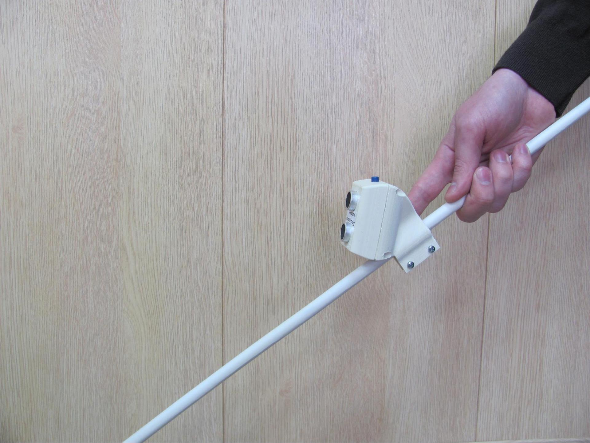
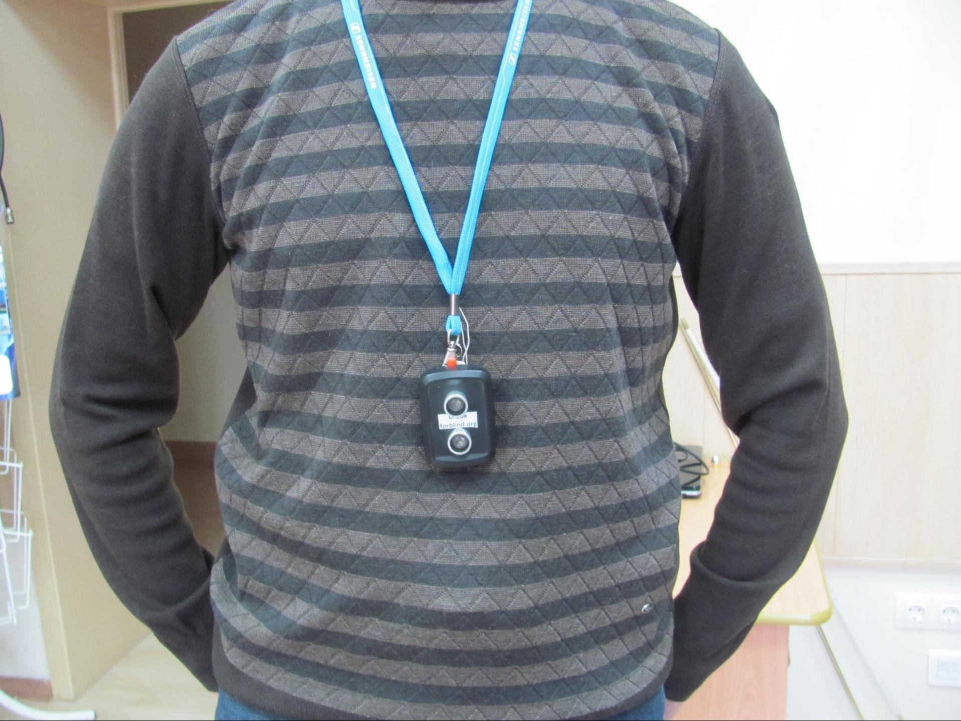
An ultrasonic cane attachment and an ultrasonic key fob are devices for blind people who warn of obstacles that are above the level at which they can be detected with a normal cane. Such obstacles can be cars with high seating, barriers, high fences. The ultrasonic nozzle is attached to a regular cane, and the ultrasonic keychain is hung on the neck or worn in your hand, like a torch.
')
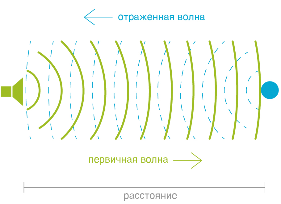
The operation of the device is based on the reflection of ultrasonic waves from obstacles. By measuring the time difference between the moment of generation of a pulse and the moment of receiving a reflected echo signal, one can determine the distance to the obstacle.
To develop devices, it is necessary to select a sensor for measuring the distance, a control board and an alarm device, select the batteries, the method of charging them and suitable enclosures.
Ultrasonic sensor
Two devices were tested for measuring the distance to an obstacle:
- Arduino-compatible ultrasonic module HC-SR04
- Car parking sensors HO 3800
Both devices work on a similar principle. The differences are in the directivity pattern of the sensors, the maximum range for determining obstacles and the design.
Comparison of sensor parameters:
| Parameter | HC-SR04 | HO 3800 |
|---|---|---|
| Maximum range, m | four | 2.5 |
| Power supply, V | five | five |
| The number of sensors in one device | one | four |
| Information output | analog | digital |
During the tests, it turned out that the HC-SR04 modules have a somewhat worse ability to detect obstacles and work in difficult climatic conditions (cold).
Both sensors, despite their differences, can be used in an ultrasonic nozzle on a cane as a means of measuring the distance to an obstacle, so the price was the main parameter for choosing a sensor. We settled on the cheaper HC-SR04 sensor.
Control board
The Arduino platform is selected as the control board. In our case, the most applicable board miniature versions: Arduino Mini, Arduino Nano or Arduino Pro Mini. In general, any other controller that provides similar capabilities can be used.
Batteries
To provide power to the device, it is advisable to use lithium-ion (Li-ion) or nickel-metal hydride (Ni-Mh) battery cells.
When operating in normal climatic conditions, it makes sense to use Li-ion batteries that have the following advantages over Ni-Mh:
- ease of implementation of the charging circuit
- availability of ready charge modules
- higher output voltage
- variety of overall dimensions and capacities
At low temperatures, it is preferable to use Ni-Mh batteries.
The voltage at the output of one Ni-Mh battery (1.0 -1.4 V) is not enough to operate the device. To obtain a voltage of 5 V (necessary for operation of both the Arduino and the controller), in addition to the batteries, we will use a step-up DC-DC converter.
For the operation of the DC-DC converters chosen by us, it is necessary to provide an input voltage of 0.9-6.0 V. To obtain the required output voltage, one Ni-Mh element with a voltage of 1.2 volts could be used. However, as the input voltage decreases, the load capacity of the converter decreases, so for stable operation of the device, it is desirable to supply at least 2 V to the converter input (two 1.2 V Ni-Mh cells or one 3.7 V Li-ion cell). Note that there are DC-DC converters for which the input voltage of 1.2 V is not enough.
Battery charging
For Li-ion batteries, there are many ready-made inexpensive modules with indication of the end of the charge.
In the case of Ni-Mh batteries, everything is more complicated. There are no ready-made embedded solutions on the market at the moment. To charge Ni-Mh batteries, you can use specialized external chargers or create your own charging circuit.
One of the ways to charge the Ni-Mh cell is a serial connection with the battery of two LM317 linear stabilizers (or similar): the first is in current limiting mode, the second is in voltage limiting mode.
The input voltage of this circuit is 7.0-7.5 V. In the absence of stabilizer cooling, it is not recommended to exceed this voltage. The voltage on each Ni-Mh battery during charging should be about 1.45 V (the voltage of a fully charged Ni-Mh cell). In order to avoid overheating and microcircuit failure, the battery charging current should not exceed 100 mA and can be increased to 200 mA using appropriate radiators.
The advantage of such a charging circuit is the absence of the need to monitor the state of charge: when the required voltage on the cell is reached, the current will automatically fall to a safe minimum.
Alarm device
Depending on the choice of the warning channel (auditory or tactile), an actuator is selected - a buzzer or a vibration motor. In addition, you can combine both methods of notification, giving the user the ability to switch between them.
During testing of prototypes, we found that it is most convenient to transmit information about the proximity of an obstacle through vibration, because in this case, the audio channel is very important for a blind person. Therefore, all products developed and assembled by us use vibration to warn of an obstacle. The intensity of the vibration is proportional to the distance to the obstacle.
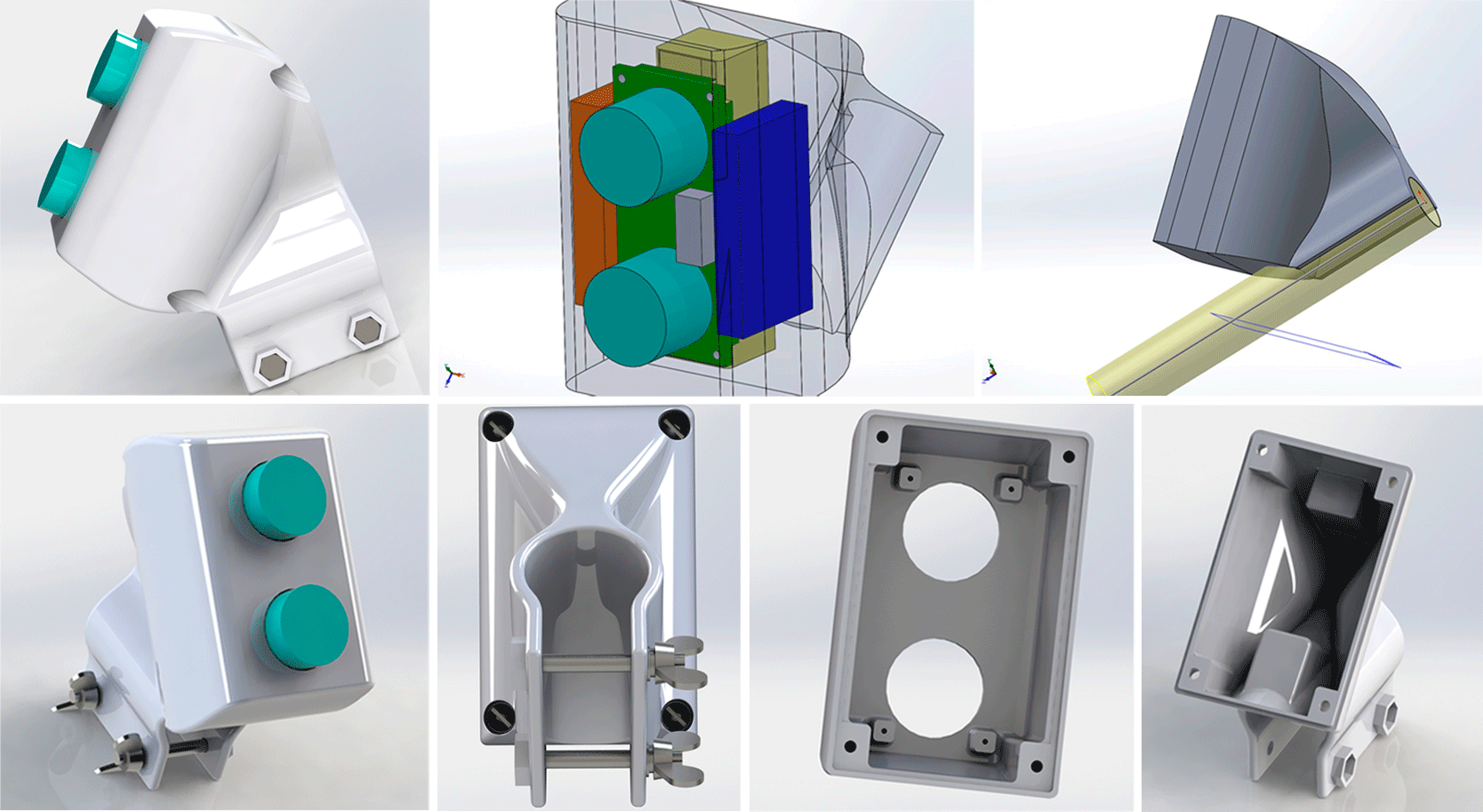
Housing
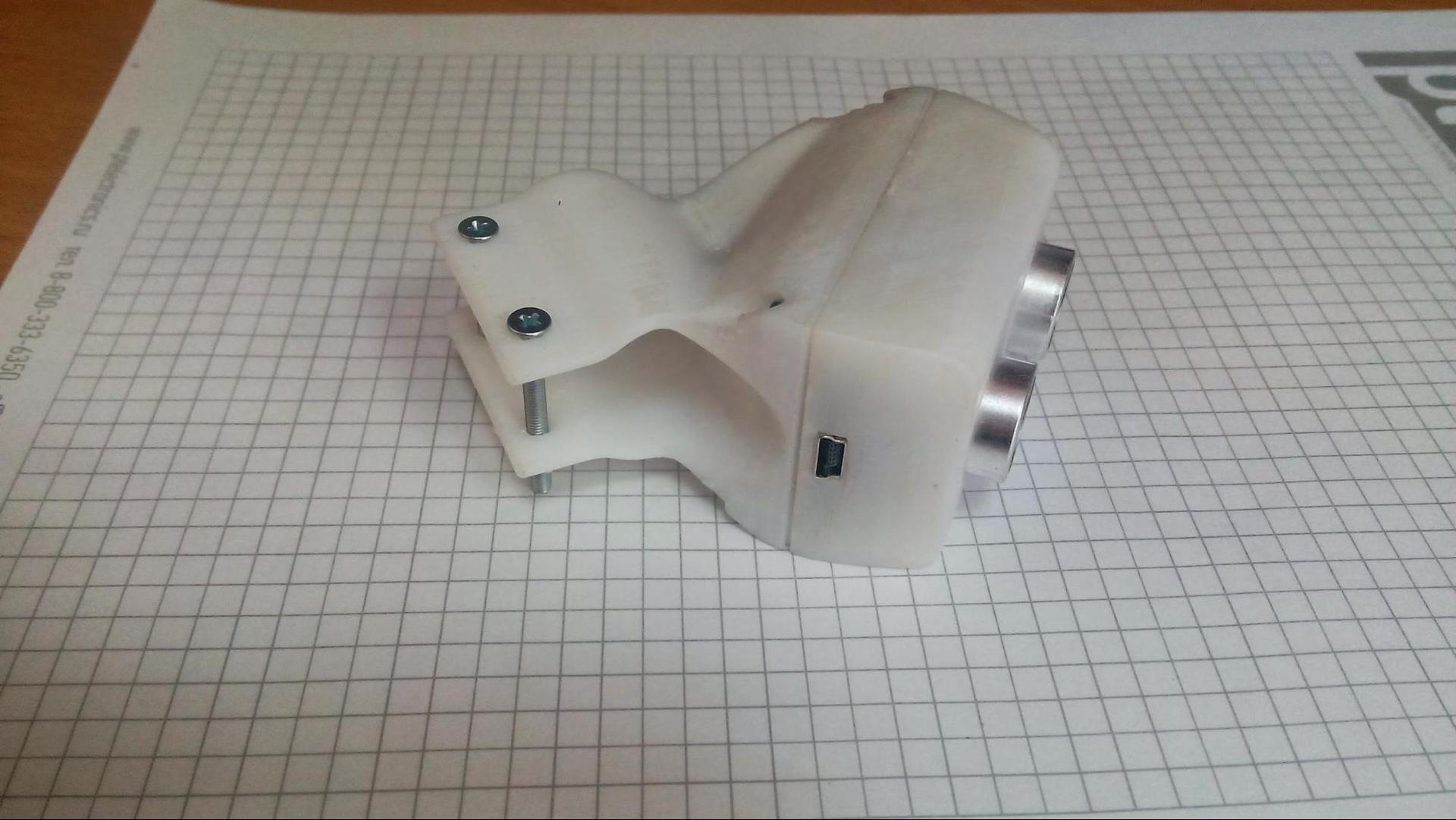
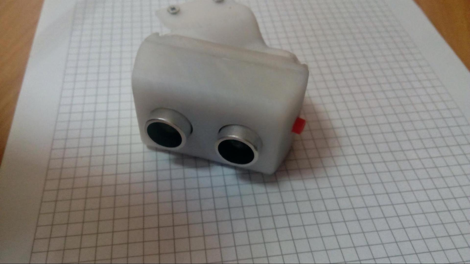
We did not manage to find a convenient case for an ultrasonic cane attachment among the mass-produced cases. To test the device, we used an ABS plastic case printed on a 3D printer. To print the case on a 3D printer, we developed the following 3D model:
The result of testing prototypes
During the development process, more than 12 variants of the product were collected. Each new product eliminated the shortcomings of the previous ones: during the development process, we reduced the size and weight of the product, picked up an ultrasonic sensor that satisfies us both in price and technical characteristics, refused to use the audio channel and optimized the device operation algorithm. Together with the blind (Bortnikov P.V., Shalintsev V.A.) all the collected items were tested. As a result, we obtained the final sample.
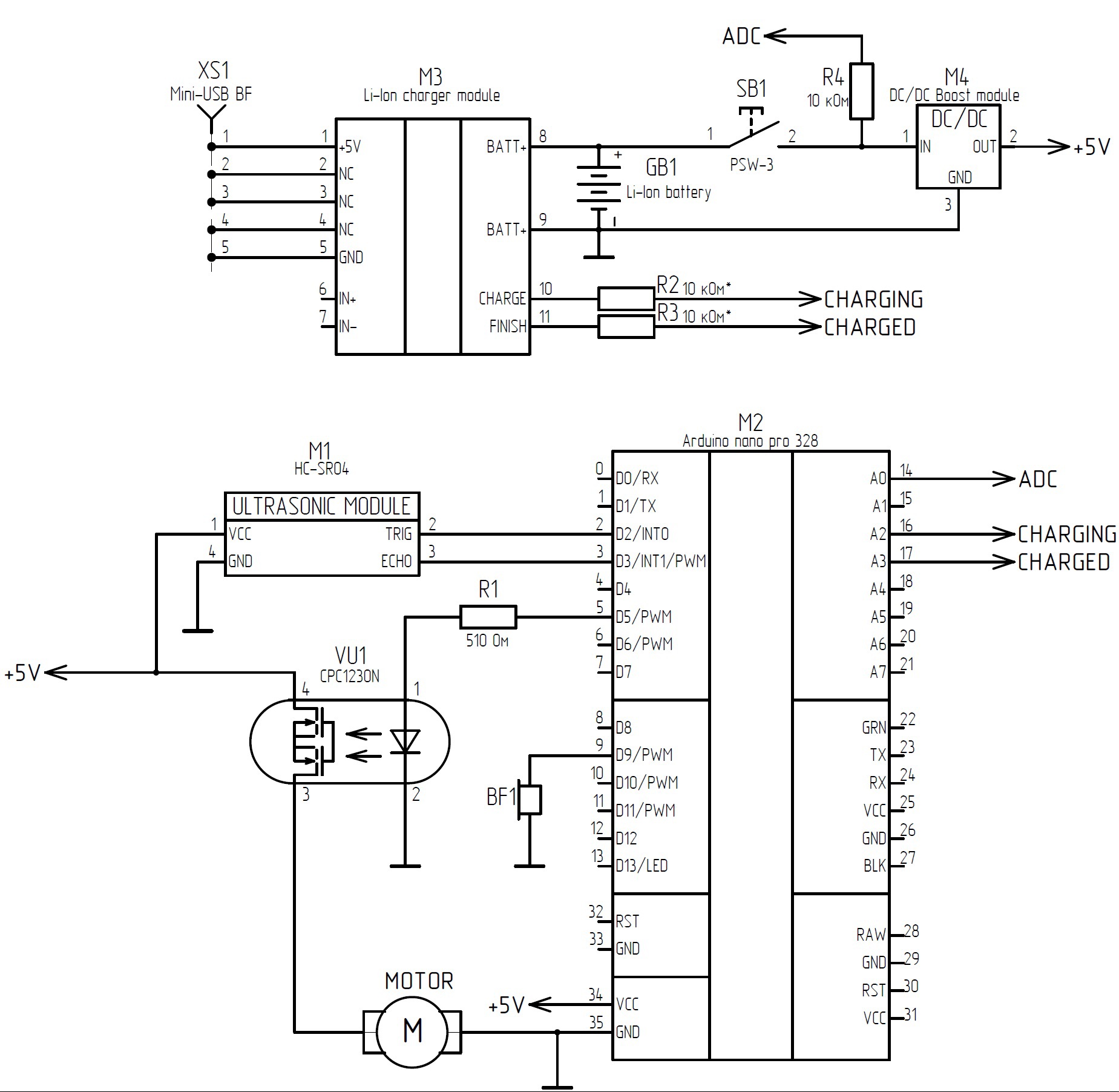
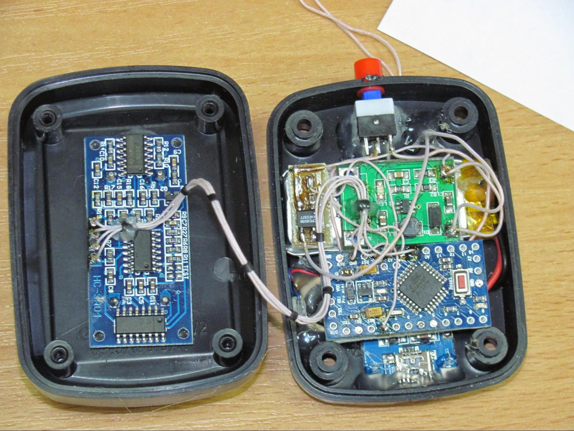
Below are the electrical circuit of the developed device:
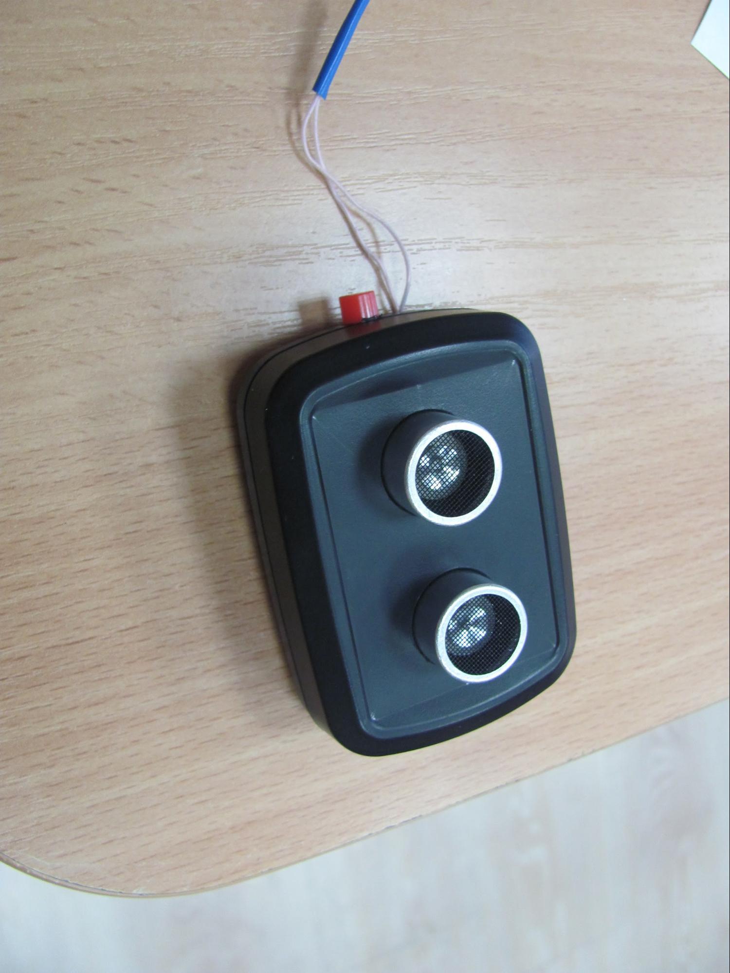
Unassembled ultrasonic key chain on the neck as follows:
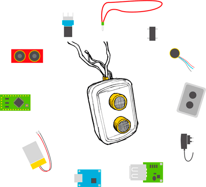
All components used in the assembly, except for the cane casing printed on a 3D printer, were purchased through AliExpress:
- Ultrasonic sensor HC-SR04.
- Adruino Pro Mini control board.
- Rechargeable battery 3.7 V 300 mAh.
- Voltage converter 0.9V ~ 5V to 5V 600 mA.
- Charging module AC / DC 220V to 5 V 1 A.
- Charger LA-520W.
- Signaling device: Vibrating motor for 4x10mm DC 3V mobile phone.
- Button PB-22E60.
- Case Gainta G1906 (for key fob).
- Transistor: bss138 / bcr108 or optocoupler CPC1230N.
The appearance and prices (taking into account the delivery from China) of the components used to assemble the ultrasonic cane attachment are shown in the figure:
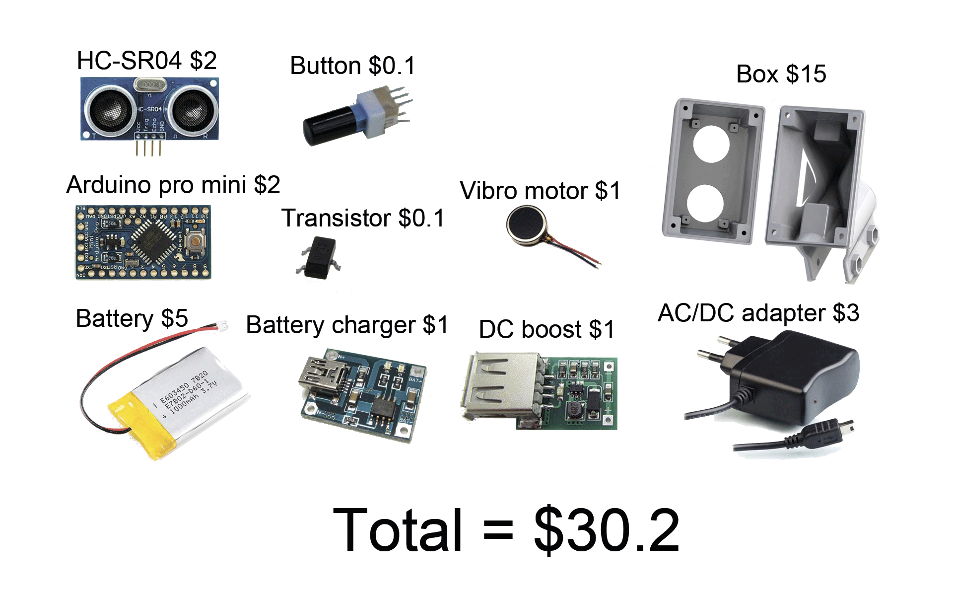
Of the components used in the assembly, the case printed on the 3D printer makes the largest contribution to the cost of the device.
The appearance and prices (taking into account the delivery from China) of the components used to assemble the ultrasonic key fob are shown in the figure:
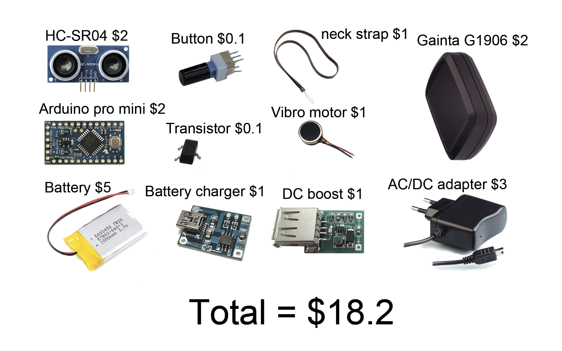
In the future, you can develop a mount to the housing Gainta G1906 and use the device with such a body as a nozzle on a cane.
One of the ways to reduce the cost of devices is to save on labor and the cost of shipping components of devices to Russia due to the deployment of production directly in China.
The devices we developed have the following characteristics:
| Characteristic | Value |
|---|---|
| Obstacle detection range | 1.5 meters |
| Average time on one charge | 8 ocloc'k |
| Number of vibration levels | 3 (1.5 m / 1.0 m / 0.7 m) |
| Charging method | mini usb |
After conducting preliminary testing of devices, we were forced to limit the detection range of obstacles to 1.5 meters in order to avoid unnecessary alarms when using devices in a stream of people. With a continuous change in the level of vibration, it is more difficult to determine the approximation of an obstacle; therefore, based on the results of preliminary tests, we stopped at three levels of vibration.
The appearance of the ultrasonic nozzle on a cane:
The appearance of the key fob on the neck:

The 3D model of the ultrasonic cane attachment and the source code of the Adruino firmware are available for download at the link .
Our plans
For the production of a small batch of products necessary for the final tests on a large sample of blind people, we began to raise funds at the crowdfunding platform Indiegogo.
Upon completion of the development on the project website, all necessary information will be laid out for organizing the production of ultrasonic nozzles on a cane and ultrasonic keyfobs (project description, design documentation, program code).
In the future, we plan to start mass production of devices for the blind. To reduce the cost and the final price of devices we will try to locate production in China.
Source: https://habr.com/ru/post/257943/
All Articles