Determining network topology at OSI levels 2/3
One of the important technologies of any serious network monitoring system is the method of detecting network element connections at the 2nd and 3rd level of the OSI model.

From the point of view of algorithms, this task is one of the most interesting ones we encountered during the development of our system.
')
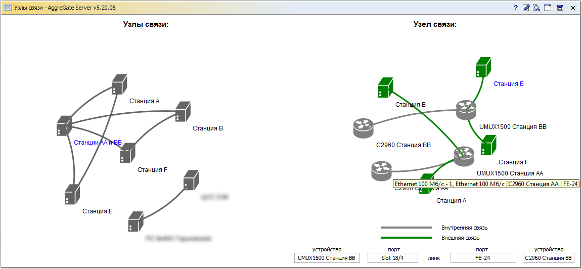
We decided to share our experience a bit, so you can imagine how a beautiful graph of connections between nodes appears on the dashboards of your monitoring system.
Network topology is a way of describing network configuration, the layout and connections of network devices. We will consider a TCP / IP network based on three types of network devices: switches, routers, and end stations. We will also assume that network devices, switches and routers provide an open interface for polling via SNMP.
To describe the topology, it is convenient to consider the OSI model of the network as a multi-storey building which is based on the foundation - this is the physical level, and the floors form a channel and network level, each subsequent level builds on the building and thus ensures the integrity and functionality of the whole structure. The task of the entire building is to provide its inhabitants, that is, various applications, with communication with each other.
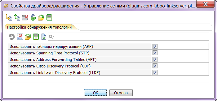
Network Manager implements a search algorithm for communications between heterogeneous devices, supporting various network topology configuration protocols, Spanning Tree Protocol (STP), Link Layer Discovery Protocol (LLDP) and Cisco Discovery Protocol (CDP). The software system architecture allows you to implement support for new protocols to detect both links at the 2nd and 3rd level of the OSI model, as well as any other logical connections between elements of the IT infrastructure.
At the data link layer, communications between devices are called second layer communications (or L2 communications). They can be specified by specifying a port pair of two directly connected switches, or a switch and an end station, or a switch and a router.
Switches support a dynamic forwarding table (AFT, address forwarding table), which stores the corresponding MAC address of the node to the switch port. This information is available through dynamic tables accessible via SNMP in the switch's BRIDGE-MIB ( dot1dBasePortTable , dot1dTpFdbTable ).
We will say that the switch sees this network device on this port if its dynamic forwarding table contains an entry that indicates to forward the datagrams intended for this network device through this port.
For a switch with BRIDGE-MIB database support, you can read dot1dBasePortTable , determine the correspondence between the interface number and the port number, and the available interfaces are determined by the MIB-II database ( ifTable table). This allows us to consider data on 2nd and 3rd level links in a unified way.
To store intermediate results in Network Manager, a topological database is used, which provides a common interface for working with the network graph and its specializations intended for work at the channel and network layers.
Automatic determination of the network topology is divided into two phases: data collection and their subsequent analysis. Data from network devices is collected in a topological database, using SNMP queries to network databases of network devices, and the types of devices and their network interfaces are determined.

At the second stage, the available data is analyzed using the selected protocols for determining the network topology; for the implementation of the algorithms, the Internet-accessible articles 1, 2 and 5 are used.
The difficulty in determining the heterogeneous network topology is that the switch forwarding tables are dynamic, they store the MAC address of the destination address and the corresponding port for some limited time specified in the device configuration and generally, at the time of the study, not all network devices exchanged datagrams and as a result routers may not have complete information about all available network devices and their connections. In addition, many corporate networks have unmanaged switches, and some switches may not be connected to the monitoring system or incorrectly support the necessary SNMP MIBs. However, if there is a network device visible on all network switches, then incomplete forwarding tables can unambiguously restore the network configuration (3).
Network heterogeneity also affects the interpretation of data received from switches that support LLDP and CDP protocols, because their proper operation requires that all nearby network devices support either LLDP or CDP protocol. As a result, the information obtained from these protocols only makes it possible to conclude that the two data network devices see each other on certain ports, but it does not make it possible to directly identify them as the nearest “neighbors”.
The search algorithm for the heterogeneous network topology, implemented in AggreGate Network Manager, primarily determines the connections between the switches. The general essence of the algorithm can be described as follows:
Consider two switches "A" and "B", located on the same subnet. If switch “A” sees switch “B” on port “a”, and switch “B” sees switch “A” on port “B” and there is no other network device in their tables that is simultaneously visible on ports “a” and “ b ", then switches" A "and" B "are connected directly to the data link layer (see 1, 3 and 5). After finding the connection, we remove the corresponding interfaces from the cache of the forwarding tables and continue the analysis of the information remaining in the tables, gradually finding the remaining connections using the exception method.
At the next stage, possible connections between switches and end stations are determined. To do this, search for the nearest switch is used: if the switch sees the end station on this port and it sees another switch on the same port, then, in the absence of network hubs, the switch cannot be the closest one (see 4). On the other hand, if the switch on the port under study sees only one end station, then this switch and the station are the nearest neighbors in our network.
With the topology of the IP-level (L3) things are much easier. Layer 3 links are quite easily determined by the routing tables ( ipRouteTable ), also accessible via SNMP.
Understanding that the versatility of our product will force us to deal with various types of topology in the future, we have designed the visual component “graph of topology” so that it can work with arbitrary tables containing descriptions of nodes and edges of the topology graph. And, as usual, with the availability of a tool, new applications were quickly found for him:

All technologies described in this article have been tested and implemented in our AggreGate Network Manager product. The operation of communication definition algorithms in conditions of insufficient data (not all switches and routers are connected via SNMP, incorrect support of necessary MIBs, etc.) is far from trivial, so we continue to improve them to this day.
What to read on:
From the point of view of algorithms, this task is one of the most interesting ones we encountered during the development of our system.
')
We decided to share our experience a bit, so you can imagine how a beautiful graph of connections between nodes appears on the dashboards of your monitoring system.
Network topology is a way of describing network configuration, the layout and connections of network devices. We will consider a TCP / IP network based on three types of network devices: switches, routers, and end stations. We will also assume that network devices, switches and routers provide an open interface for polling via SNMP.
To describe the topology, it is convenient to consider the OSI model of the network as a multi-storey building which is based on the foundation - this is the physical level, and the floors form a channel and network level, each subsequent level builds on the building and thus ensures the integrity and functionality of the whole structure. The task of the entire building is to provide its inhabitants, that is, various applications, with communication with each other.
Network Manager implements a search algorithm for communications between heterogeneous devices, supporting various network topology configuration protocols, Spanning Tree Protocol (STP), Link Layer Discovery Protocol (LLDP) and Cisco Discovery Protocol (CDP). The software system architecture allows you to implement support for new protocols to detect both links at the 2nd and 3rd level of the OSI model, as well as any other logical connections between elements of the IT infrastructure.
At the data link layer, communications between devices are called second layer communications (or L2 communications). They can be specified by specifying a port pair of two directly connected switches, or a switch and an end station, or a switch and a router.
Switches support a dynamic forwarding table (AFT, address forwarding table), which stores the corresponding MAC address of the node to the switch port. This information is available through dynamic tables accessible via SNMP in the switch's BRIDGE-MIB ( dot1dBasePortTable , dot1dTpFdbTable ).
We will say that the switch sees this network device on this port if its dynamic forwarding table contains an entry that indicates to forward the datagrams intended for this network device through this port.
For a switch with BRIDGE-MIB database support, you can read dot1dBasePortTable , determine the correspondence between the interface number and the port number, and the available interfaces are determined by the MIB-II database ( ifTable table). This allows us to consider data on 2nd and 3rd level links in a unified way.
To store intermediate results in Network Manager, a topological database is used, which provides a common interface for working with the network graph and its specializations intended for work at the channel and network layers.
Automatic determination of the network topology is divided into two phases: data collection and their subsequent analysis. Data from network devices is collected in a topological database, using SNMP queries to network databases of network devices, and the types of devices and their network interfaces are determined.
At the second stage, the available data is analyzed using the selected protocols for determining the network topology; for the implementation of the algorithms, the Internet-accessible articles 1, 2 and 5 are used.
The difficulty in determining the heterogeneous network topology is that the switch forwarding tables are dynamic, they store the MAC address of the destination address and the corresponding port for some limited time specified in the device configuration and generally, at the time of the study, not all network devices exchanged datagrams and as a result routers may not have complete information about all available network devices and their connections. In addition, many corporate networks have unmanaged switches, and some switches may not be connected to the monitoring system or incorrectly support the necessary SNMP MIBs. However, if there is a network device visible on all network switches, then incomplete forwarding tables can unambiguously restore the network configuration (3).
Network heterogeneity also affects the interpretation of data received from switches that support LLDP and CDP protocols, because their proper operation requires that all nearby network devices support either LLDP or CDP protocol. As a result, the information obtained from these protocols only makes it possible to conclude that the two data network devices see each other on certain ports, but it does not make it possible to directly identify them as the nearest “neighbors”.
The search algorithm for the heterogeneous network topology, implemented in AggreGate Network Manager, primarily determines the connections between the switches. The general essence of the algorithm can be described as follows:
Consider two switches "A" and "B", located on the same subnet. If switch “A” sees switch “B” on port “a”, and switch “B” sees switch “A” on port “B” and there is no other network device in their tables that is simultaneously visible on ports “a” and “ b ", then switches" A "and" B "are connected directly to the data link layer (see 1, 3 and 5). After finding the connection, we remove the corresponding interfaces from the cache of the forwarding tables and continue the analysis of the information remaining in the tables, gradually finding the remaining connections using the exception method.
At the next stage, possible connections between switches and end stations are determined. To do this, search for the nearest switch is used: if the switch sees the end station on this port and it sees another switch on the same port, then, in the absence of network hubs, the switch cannot be the closest one (see 4). On the other hand, if the switch on the port under study sees only one end station, then this switch and the station are the nearest neighbors in our network.
With the topology of the IP-level (L3) things are much easier. Layer 3 links are quite easily determined by the routing tables ( ipRouteTable ), also accessible via SNMP.
Understanding that the versatility of our product will force us to deal with various types of topology in the future, we have designed the visual component “graph of topology” so that it can work with arbitrary tables containing descriptions of nodes and edges of the topology graph. And, as usual, with the availability of a tool, new applications were quickly found for him:
- Route Topology EIGRP, OSPF, BPG, etc.
- Visualize paths in the MPLS cloud
- SDH / PDH topology
- Visualize links between hypervisors and virtual machines running on them
- Manually added parent-child links between nodes
- Graph of the dependence of IT service components on infrastructure elements
All technologies described in this article have been tested and implemented in our AggreGate Network Manager product. The operation of communication definition algorithms in conditions of insufficient data (not all switches and routers are connected via SNMP, incorrect support of necessary MIBs, etc.) is far from trivial, so we continue to improve them to this day.
What to read on:
- Topology Discovery in Heterogeneous IP Networks: The NetInventory System . Y.Breitbart, M.Garofalakis, B.Jai, C.Martin, R.Rastogi, and A.Silberschatz IEEE / ACM TRANSACTIONS ON NETWORKING, VOL. 12, NO. 3, JUNE 2004
- Layer-2 Path Discovery Using Spanning Tree MIBs . David T. Stott, Avaya Labs Research, Avaya Inc., Basking Ridge, NJ, Tech. Rep
- Finding Ethernet-Type Network Topology is Not Easy . H. Gobjuka, Y. Breitbart, Technical Report: TR-KSU-CS-2007-03, Kent State University, 2007.
- Automatic detection and description of the network infrastructure of supercomputers . V. Voevodin, K. Stefanov, Computational Methods and Programming. 2014. T. 15
- IP Network Topology Discovery Using SNMP . Suman Pandey, Mi-Jung Choi, Sung-Joo Lee, James W. Hong, Dept. of Computer Science and Engineering, POSTECH, Korea
Source: https://habr.com/ru/post/257911/
All Articles