Layered menu for Arduino and not only

A few months ago, an article titled “Implementing a multi-level menu for Arduino with a display” appeared on the desktop. But wait, I thought. “I wrote this menu six years ago!”
Back in 2009, I wrote the first project based on a microcontroller and a display called “Automatic Lighting Control”, for which it was necessary to create such a menu shell, which will fit a thousand configs, or even more. The project was successfully born, compiled and able to work until now, and the OS menu shell went to wander from project to project, using the best practices of Damage-Oriented Programming . “Stop tolerating it,” I said, and rewrote the code.
')
You will find a legacy code of selective quality, a tale about how I rewrote it, as well as instructions for those who want to use it.
Requirements and features of the OS menu
To begin with, we will define the requirements that we make to the menu:
- ease of use, buttons left-right, up-down, back-forward .;
- tree structure of any adequate depth (up to 256);
- the total number of menu items, which is enough for everyone (10 ^ 616);
- editing settings;
- launch programs.
- simple built-in task manager.
And yet, it is necessary that all this weigh as little as possible, be unpretentious to resources and run on any platform (as long as it is available for the AVR, it works with GLCD and text LCD).
Theoretically, with the appropriate drivers, this OS menu can be simply taken and connected to the RTOS.
File structure
As an example, we will analyze the following menu structure (on the left is the item number):
0 / 1 - 1/ - 3 -- 1 4 -- 2 5 -- 3/ - . 6 --- 3.1 6 --- 3.2 6 --- 3.3 6 --- 6 --- 3.64 2 - 2/ - 7 -- 1 8 -- 2 9 -- 3 10 -- / The main dogma of the OS menu is "Everything is a file." Let it be so.
Each file has a type, name, parent folder, other parameters
We describe the structure:
struct filedata{ uint8_t type; uint8_t parent; uint8_t mode1;// 1 uint8_t mode2;// 2 char name[20]; }; For each file, we define 4 bytes in the fileData array:
- type,
- parent, it is not very necessary, since all the information is in bread crumbs, but remained as legacy
- mode1, two parameters specific to each file type
- mode2
type == T_FOLDER
The main file is a folder. It allows you to create a tree structure of the entire menu.
The most important here is the root folder numbered zero. Whatever happens, we will eventually return to it.
Folder parameters are
mode1 = , mode2 = . In the root folder 0 are files 1 and 2, only 2 pieces.
We describe it as:
T_FOLDER, 0, 1, 2, type == T_DFOLDER
Folder 3 contains several copies of the same program, but with different startup keys.
For example, in the automatic lighting control it is possible to install up to 64 daily programs, with 16 intervals each. If you describe each item, you need 1024 files. In practice, two is enough. And bread crumbs feed the program in the form of parameters.
mode1 = , mode2 = . Simple mathematics tells us that if all 256 files are dynamic folders with the maximum number of copies, the total number of menu items in the system will be 256 ^ 256 = 3.2 x 10 ^ 616. This EXACTLY enough for any adequate and not very occasion.
type == T_APP
Application. His task is to register in the task manager (built-in or external), take control of the buttons and edit.
mode1 = id . type == T_CONF
Config-file, for which all the fuss has been started. Allows you to set the boolean or numeric value of any parameter. Works with int16_t.
mode1 = id The config has its own configsLimit array, where for each config there are three int16_t configuration numbers:
- Cell ID - The starting number of the memory cell for storing data. All data is two bytes.
- Minimum - the minimum value of the data
- Maximum - the maximum value of the data.
For example, in cell 2 you can write a number from -100 to 150, then the line will look like:
2, -100, 150, type == S_CONF
An interesting (but still remaining only in the old code) config file, working in conjunction with T_SFOLDER
mode1 = id type == T_SFOLDER
A special kind of folder is rendered closer to the configuration, since it is one of its varieties.
Imagine if your system is protected by the possibility of working on RS-485 using protocols A, B or C. We place in the folder a handful of files like S_CONF and select the necessary one from them. Moreover, when we go into the folder again, the cursor highlights the active option.
mode1, mode2 are similar for T_FOLDER. Child files are only T_SCONF
Refactoring results
I did not set myself the task of revising the architecture, in many places I even left the logic of work as it is. There are very funny crutches.
The main task is to sort out the system so that its use in new projects is simple. Eventually:
- Allocated work with the hardware at least in separate functions in a separate file. HWI includes:
- Rewrote modules for classes. All that is possible is hidden in private, the appearance is unified, the Chip with classes and a more or less unified interface will come in handy later.
- "Added" interface for working with RTOS. Rather, the regular task manager is quite easy to replace with any other.
- Tritely tidied up the code, made it clearer, removed the magic numbers, improved the interface. Now it is not a shame to show it.
I was too lazy to rewrite the clock setting module under hwi. All the same, it must be completely redone. He is terrible.
How was refactoring, you can clearly see in the repository.
Creating your project
Setting up the project includes the following items:
Creating files
Create arrays according to the previously considered structure
// static const uint8_t fileStruct[FILENUMB*FILEREW] PROGMEM = { T_FOLDER, 0, 1, 2, //0 T_FOLDER, 0, 3, 3, //1 T_FOLDER, 0, 7, 4, //2 T_APP, 1, 1, 0, //3 T_APP, 1, 2, 0, //4 T_DFOLDER, 1, 6, 66, //5 T_APP, 5, 2, 0, //6 T_CONF, 2, 0, 0, //7 T_CONF, 2, 1, 0, //8 T_CONF, 2, 2, 0, //9 T_APP, 2, 3, 0 //10 }; // static PROGMEM const char file_0[] = "Root"; static PROGMEM const char file_1[] = "Folder 1"; static PROGMEM const char file_2[] = "Folder 2"; static PROGMEM const char file_3[] = "App 1"; static PROGMEM const char file_4[] = "App 2"; static PROGMEM const char file_5[] = "Dyn Folder"; static PROGMEM const char file_6[] = "App"; static PROGMEM const char file_7[] = "config 0"; static PROGMEM const char file_8[] = "config 1"; static PROGMEM const char file_9[] = "config 2"; static PROGMEM const char file_10[] = "Date and Time"; PROGMEM static const char *fileNames[] = { file_0, file_1, file_2, file_3, file_4, file_5, file_6, file_7, file_8, file_9, file_10 }; Create an array for configs:
//number of cell(step by 2), minimal value, maximum value static const PROGMEM int16_t configsLimit[] = { 0,0,0,// config 0: 0 + 0 2,-8099,8096,//config 1 4,1,48,//config 2 }; Button customization
I prefer to connect the buttons with a ground fault and a pull-up resistor to the power supply, which is always available in the MK.
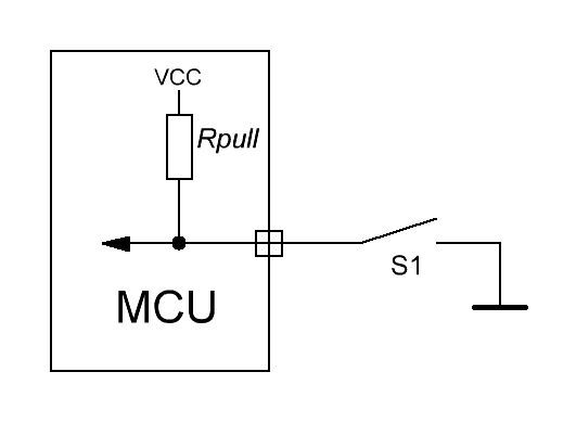
In the file hw / hwdef.h we indicate the names of the registers and the location of the buttons:
#define BUTTONSDDR DDRB #define BUTTONSPORT PORTB #define BUTTONSPIN PINB #define BUTTONSMASK 0x1F #define BSLOTS 5 /**Button mask*/ enum{ BUTTONRETURN = 0x01, BUTTONLEFT = 0x02, BUTTONRIGHT = 0x10, BUTTONUP = 0x08, BUTTONDOWN = 0x04 }; Display setting
Now the project is dragging the GLCDv3 library along, which is not good. Historically it happened.
Google-code link - https://code.google.com/p/glcd-arduino
Create application
Consider an example application that uses the basic menu functions.
menuos / app / sampleapp.cpp
Create a class with the following structure:
#ifndef __SAMPLEAPP_H__ #define __SAMPLEAPP_H__ #include "hw/hwi.h" #include "menuos/MTask.h" #include "menuos/buttons.h" class sampleapp { //variables public: uint8_t Setup(uint8_t argc, uint8_t *argv);// . - uint8_t ButtonsLogic(uint8_t button);// uint8_t TaskLogic(void);// protected: private: uint8_t tick; void Return();// //functions public: sampleapp(); ~sampleapp(); protected: private: }; //sampleapp extern sampleapp SampleApp; // <s></s> void SampleAppButtonsHandler(uint8_t button); void SampleAppTaskHandler(); #endif //__SAMPLEAPP_H__ And outline the main functions:
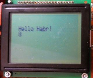
uint8_t sampleapp::Setup(uint8_t argc, uint8_t *argv) { tick = 0; // Buttons.Add(SampleAppButtonsHandler);//add button handler Task.Add(1, SampleAppTaskHandler, 1000);//add task ha GLCD.ClearScreen();// // GLCD.CursorTo((HwDispGetStringsLength()-11)/2, HwDispGetStringsNumb()/2); GLCD.Puts("Hello Habr"); return 0; } Wrappers:
void SampleAppButtonsHandler(uint8_t button){ SampleApp.ButtonsLogic(button); } void SampleAppTaskHandler(){ SampleApp.TaskLogic(); } Button handler:
uint8_t sampleapp::ButtonsLogic(uint8_t button){ switch (button){ case BUTTONLEFT: break; case BUTTONRIGHT: break; case BUTTONRETURN: Return(); break; case BUTTONUP: break; case BUTTONDOWN: break; default: break; } return 0; } And the function that will be called every second:
uint8_t sampleapp::TaskLogic(void){ GLCD.CursorTo((HwDispGetStringsLength()-11)/2, HwDispGetStringsNumb()/2+1); GLCD.PrintNumber(tick++); } Now in menu.cpp we will prescribe that our program will be called according to number 2:
void MMenu::AppStart(void){ if (file.mode2 != BACKGROUND){ Task.Add(MENUSLOT, MenuAppStop, 10);//100 ms update Task.ActiveApp = 1;//app should release AtiveApp to zero itself } switch (file.mode1){//AppNumber case 2: SampleApp.Setup(level, brCrumbs); break; case 3: Clock.Setup(level, brCrumbs); break; default: Task.ActiveApp = 0; break; } } Let's collect the project and see what we have:
Same for visuals
Detailed and slightly boring instructions on the file structure and architecture, as well as an example of working in video.
Links and repositories
The project is built in the Atmel Studio programming environment, but that day will come and it will be forknut and under Eclipse. The current version of the project is available in any repository (Backup).
- GitHub repository: https://github.com/radiolok/menuosv1
- Bitbucket repository: https://bitbucket.org/radiolok/menuosv1
- GLCDv3: https://code.google.com/p/glcd-arduino/
- openLCD: https://bitbucket.org/bperrybap/openglcd/
Source: https://habr.com/ru/post/257607/
All Articles