Another way to connect WS2812B to a microcontroller

The topic of connecting WS2812B LED bars to various microcontrollers, as well as their programming, is quite popular today.
I will not dwell on the protocol. It is enough to say that the coding of bits 0 and 1 is carried out by pulses of different duration. The output of these impulses is just a headache when programming an MCU (I do not take into account the use of ready-made libraries for Arduino, since the purpose of the article is to show the details of the process).
')
My choice of microcontroller fell on the TI Stellaris LM4F120 for two reasons:
- Was available (low-cost LaunchPad from TI);
- My project is quite demanding of resources, and the MCU ARM® Cortex ™ -M4F with Direct Memory Access (DMA) capabilities is just the right solution.
There are various options for organizing data output using the WS2812B protocol on ARM microcontrollers:
- Output via SPI with multi-bit packages per bit (1000, 1110);
- Output via PWM.
In both cases, use direct memory access, which unloads the processor. In this case, the disadvantage of both solutions is the extra consumption of RAM under the buffer.
I decided to follow the path of using SPI DMA, but so that there was no need to “inflate” every bit to a few. I was interested in the ability to output data via SPI "as is". Those. 24 bits per LED, at 800 kHz. This required a small SPI converter -> WS2812B. This may seem superfluous to “fence the garden” if you can directly connect everything. But I still needed to make a board, on which, apart from the protocol converter, there was also an SD memory card connector, as well as a 12V -> 5V / 5A switching converter (the line of 144 LEDs is quite voracious, which, moreover, imposes a restriction on the length and cross section its wires feeding). And the problem of converting the logic level of 3.3V to 5V is also being solved.
I give a circuit diagram (only 2 74HCT cases are used).
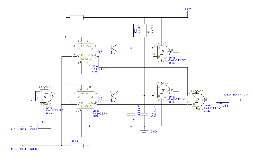
The values of resistors R1 and R2 are approximate, are chosen empirically using an oscilloscope (you need to derive the test sequence from the microcontroller, measure the duration with an oscilloscope and adjust the ratings as needed). The real scheme is slightly different, since I did not have 74HCT132 and 74HCT74 in stock, but there were 74HC74, 74HCT14 and 74HCT00, so there were 3 cases.
The circuit has been tested in field conditions on a line of 144 LEDs and on the length of the wire between the output of the circuit and the LED input is on the order of a meter. Any failures and interference was not observed.
By the way, about the wires. As I mentioned above, the LED stripes on the WS2812B eat a decent current at maximum power. Accordingly, it is necessary to select the cross-section of the supply wire, sufficient for the voltage drop across it to be non-critical. I took a piece of three-wire power wire (normal, which for 220V) with a cross section of 1mm 2 . Even this section was not enough for the wire length of 1M. At 50% of the power of all simultaneously turned on LEDs, the voltage "sank" to 4 Volts. Another phenomenon that should not be forgotten is that when the supply voltage sags, the data line remains at 0V and 5V. Thus, in relation to the power supply of the first LED, the level is lower than GND and higher than VCC with the risk of disabling the input leg. Therefore, in addition, I put the Schottky diode on the ground and the power just before the data input of the first LED.
In the next article I will tell you what kind of device I got.
Source: https://habr.com/ru/post/257321/
All Articles