Implementing the ws2812b protocol on ATmega
 LEDs ws2812b is a very interesting thing. I want to tell now about the implementation of the protocol of their work. As in the previous article , the code was written in the IAR environment under the ATmega32 microcontroller with 16 MHz quartz. I want to clarify right away that less than 16 MHz quartz is most likely not enough, this protocol is designed for very tight timings. A zero is set at a time interval of 0.4 µs, a unit of 0.8 µs.
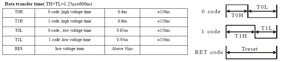
')
First of all, let's write the functions of setting 0 and 1 into the line. The number of nop'ov in functions is chosen experimentally through a logic analyzer. Screenshots are attached a little lower.
#define ClearOutBit PORTC &= ~(1<<1) //0 #define SetOutBit PORTC |= 1<<1 //1 void Set0( void ) // ~0.4 { SetOutBit; asm("nop");asm("nop");asm("nop");asm("nop");asm("nop"); ClearOutBit; // , , } void Set1( void ) // ~0.85 { SetOutBit; asm("nop");asm("nop");asm("nop");asm("nop");asm("nop");asm("nop");asm("nop");asm("nop");asm("nop");asm("nop");asm("nop"); ClearOutBit; // , , } Next we have an array of values. I created a 32 bit array of 30 values (yes, I understand that this is overkill, but it seemed to me this solution is valid). For each LED, we need to load 24 bits, with the first value being unloaded to the line for green, then red and then blue.

It takes no more than 4 ms for the controller to align values for all 30 LEDs, which is quite fast. Of course, if you increase the clock frequency, you can gain some time between bits. Ideally, if all time slots match, for 30 LEDs the load will last less than 1 ms.
unsigned long int mas[30]; //32 30 void setMas( void ) // { unsigned long int a; unsigned int j,i; for (j=0; j<30; j++) { // 30 a = 0x1000000; // G (Hi->Low), R B for (i=0;i<24;i++){ // G,R,B a=a>>1; if ((mas[j]&a)==0x00000000) { Set0(); // } else { Set1(); // } } } } In fact, it turns out that only “high voltage time” time intervals of 0.4 and 0.8 µs are maintained, while the “low voltage time” program is not controlled by the program - they are obtained by operating the microcontroller between setting values in a line. After all, he needs time to check the condition and scroll through the cycle. But nevertheless, the LEDs catch the package regularly. And of course this time should not exceed 50 µs, otherwise the LED will perceive it as a Reset and load the received “incomplete” value to itself on the display.


At the end of the article there is a video of the work of these 30 LEDs with a circular shift of the original array by timer and controlled via an IR remote control with the NEC protocol . It turned out fun.
Source: https://habr.com/ru/post/257057/
All Articles