Implementation of the NEC IR protocol on ATmega
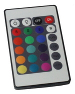 This protocol is already described in many places. I want to show and describe in detail my implementation on a specific microcontroller. I needed to receive a signal from an RGB remote control - like the one in the picture. His command system is shown at the bottom of the article.
Short excursion
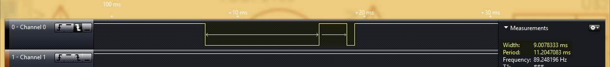
Each packet of the NEC protocol consists of a starting sequence — a pulse of 9 ms length and a pause length of 4.5 ms. In order not to load you with theoretical figures, I will show real screenshots from the logic analyzer.

The protocol itself is based on encoding zeroes and ones with a pause length. The beginning of each bit is determined by a pulse length of 560 μs (at the same time this pulse signals the end of the previous bit). The length of the pause following the impulse determines the logical value of the bit. So, the total length of the logical zero is 1.12ms, and the logical unit is 2.25ms. Accordingly, in a real situation, the values differ slightly.
')


A package consists of a starting sequence, an address, and a command. In the standard protocol version, a packet always has a fixed duration, since the address and command are transmitted both in direct and in inverse form.

When you hold the button, the parcel is not retransmitted. Instead, a special retry code with a duration of 11.25 ms is transmitted every 110 ms.
Program
I did not accept the address, because I do not need it. If necessary, you can easily modify the program. The ATmega32 with 16 MHz quartz was chosen as the microcontroller. Therefore, all time intervals are calculated for 16 MHz. To implement the protocol, we need a timer for timing and an external interrupt on a falling edge. The timer is configured with a divider of 1024, one clock of 1024/16 MHz = 64 μs, an overflow interrupt 64 μs * 256 = 16 ms (which is obviously greater than any of the bits in the packet, it will be useful to us).
Initial initialization and start / stop macros of the timer look like this:
#define StopT0 TIMSK &= ~(1 << TOIE0); // #define StartT0 TIMSK |= (1 << TOIE0); // SREG|= (1<<7); //Global Interrupt Enable GICR|= (1<<INT0); // INT0 MCUCR|=(1<<ISC01)|(0<<ISC00); // TCCR0|=(1<<CS02)|(1<<CS00); // 1024, 64, 16,38 asm("sei"); // The code is written in the IAR environment, but is easily transferred to another environment by replacing interrupt headers.
The timer overflow interrupt is only needed to “complete” the reception. An overflow of 16ms is greater than any component of a packet, be it a preamble or a bit, so that such an interruption can be considered the end of packet reception and prepare to receive the next one.
Here I had one nuance, the explanation of which I do not know. When the timer started immediately (by itself after processing the interrupt INT0), the timer overflow interrupt was triggered. How? What for? Perhaps it was some kind of individual joint, because at that time the general program was no longer small, but I decided not to process the first interrupt, but to process the second, that is, after 32ms.
#pragma vector=TIMER0_OVF_vect __interrupt void TIMER0_interrupt (void) // 0 16, { if (firstT ==0) { firstT = 1; } /* , . , 32. */ else { startC = 0; // firstT = 0; // "" StopT0; // } } Drop-down interrupt INT0. Here we count the bits and analyze the time elapsed since the last interruption. By the size of the TCNT0 timer, it is easy to understand what bit it was. At the end of the handler, the timer is reset to start the countdown from the beginning.
#pragma vector=INT0_vect __interrupt void INT0_interrupt (void) { if (startC == 0) { // newC = 0; // startC = 1; // StartT0; // 0 } else { // 64, if(TCNT0>0xD2 & TCNT0<0xFF){ //13,5 ( 13,4 ... 16,3 ) i = 32; // } if(TCNT0>0x07 & TCNT0<0x16){ //1,12 ( 0,45 ... 1,41 ) if ((i>0) & (i<9)) Command1 &= ~(1<<(i-1)); // if ((i>8) & (i<17)) Command |= (1<<(i-9)); // i--; } if(TCNT0>0x19 & TCNT0<0x28){ //2,25 ( 1,60 ... 2,56 ) if ((i>0) & (i<9)) Command1 |= (1<<(i-1)); // if ((i>8) & (i<17)) Command &= ~(1<<(i-9)); // i--; } if(TCNT0>0xA9 & TCNT0<0xB8){ //11,25 ( 10,8 ... 11,8 ) newC = 1; // } if (i==0) { // StopT0; // newC = 1; // startC = 0; // firstT = 0; // "" } } TCNT0 = 0; // } In the main program, we analyze the flag newC, not forgetting to reset it. Well, further processing command.
while(1) { if (newC) { // ? newC = 0; // if (Command == Command1) { // ? switch (Command) { // case 0x5F: { } //Up case 0xDF: { } //Down //........... } } } } Command system
And here is the command system for the ED618 console (I buy them on dx.com):

For other such RGB remotes, the command system may be different. I have exactly the same remote control, I got from some purchased RGB controller, so there the command system is quite different. Read and see for yourself. For example, I took the command and dropped it on the UART via a computer.
The algorithm itself is not complicated, I hope someone will come in handy. I have already done more than one remote-based device with such a protocol, everything works well. In the next article I will discuss the implementation of the ws2812b LED protocol .
Source: https://habr.com/ru/post/257041/
All Articles