High-precision time synchronization for measuring delay in ethernet networks

On Habré, there was already a note on how PTPv2 works . I'm going to talk about how and why this method of high-precision synchronization was implemented in our devices.
What is it for
I work for the Russian company STC-Metrotek, which develops and produces a bunch of all kinds of hardware (switches, testers, balancers, etc.) for communication systems, including testers for ethernet networks. For example, like this . One of the parameters measured by this device is the delay in passing the packet in the network under test. Ha, the reader of Habrahabr will say - the delay can be measured with a ping. That's the way it is, but with a different network load, there can be a different delay. Our device can measure the delay with an accuracy of several nanoseconds and at the same time create a load of up to 10 Gb / s.
To measure the delay, a time stamp is inserted into each packet generated by the analyzer, and when this packet is received, the difference between the current time and the data from the tag is determined. This difference is the delay. But since usually the traffic from the analyzer goes to a special device (loop) that wraps this traffic back to the tester, the measured delay is the sum of the packet transit time from the tester to the loop (upstream) and from the loop to the tester (downstream). If the channel is symmetrical, that is, its parameters are equal in both directions, then a delay in one direction can be obtained simply by dividing the measured value by two.
')

In the case when the channel is not symmetrical, it is necessary to measure the delay separately in each of the directions. It uses two analyzers. One generates test traffic, the second one receives and analyzes it.
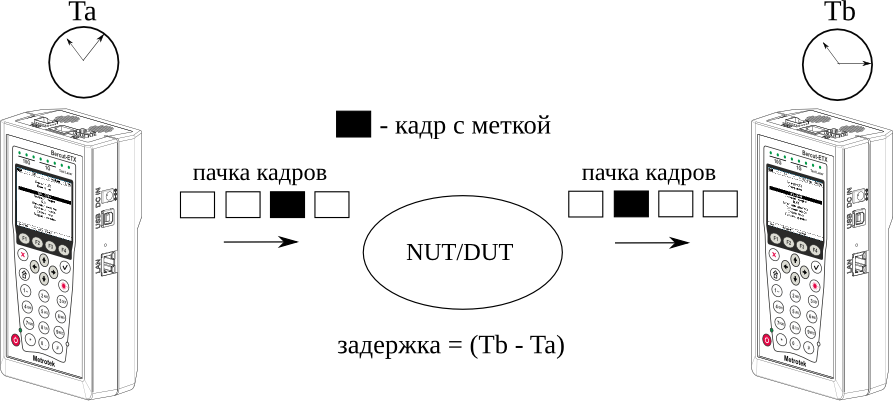
It was then that the high-precision time synchronization was required, since in order to correctly determine the delay it is necessary that the time counters on both devices have the same value.
How implemented by us
A simplified diagram of our device can be represented as follows:
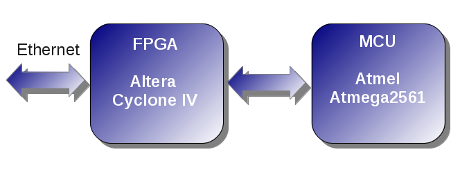
The FPGA is responsible for counting the time, it implements a time counter operating from a frequency of 125 MHz (hence the accuracy of 8 ns). The time counter may differ from the reference hours by the time shift. either lag behind or rush to some constant value. The rate of change may also differ, that is, in a second the ideal counter counts 1 * 10 ^ 9 nanoseconds, and the real one can count either more or less, as a result of which the displacement is constantly either increasing or decreasing. To correct these errors in the FPGA, the following scheme is implemented:

The current value of the counter can be changed to the specified value using the offset register. For smooth adjustment, an additional counter is used, when it reaches the set value (drift), the time counter either skips one clock cycle, or instead of 1, it increases by 2. That is, if you set 10, then in ten cycles the time counter will change to 11, for 20 cycles to 22, and so on. If a negative number is specified, for example, -10, then in 10 cycles the time counter will change to 9, in 20 cycles to 18, etc.
Our device uses a network stack of the operating system NutOs , running on an 8-bit microcontroller avr-atmega2561. And if we take into account that there are still many other tasks running on this microcontroller, and it works at 8 MHz, it becomes clear that the performance of this system is extremely small. Therefore, the part of the actions that require high accuracy is performed by the FPGA, and only the PTPv2 protocol logic is implemented on the microcontroller.
If you look at the exchange diagram, you can see that when implementing a PTPv2 client (Slave), you need to know exactly the time when a packet comes from the server (t2) and the time when the answer was sent to it (t3).
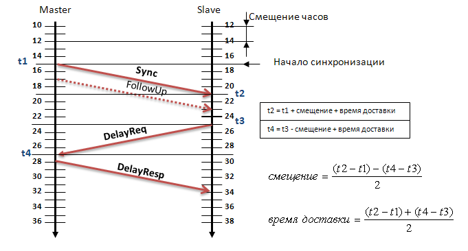
For these purposes, we modified the MAC core in the FPGA. When receiving network packets, a time stamp is added to each of them (t2). And when sending packets, the current value of the time counter (t3) is placed in a special register. Based on these values, the microcontroller calculates the current time mismatch between the reference source and the device.
To test our implementation as a PTPv2 server, we first used a regular computer that was running the ptpd daemon. In order for the daemon to work with PTP over ethernet (by default, it only works over UDP), you must enable libpcap. To do this, you need to specify the -with-pcap-config key during configuration.
When running ptpd, you must specify the configuration file, for example, like this:
ptpengine: interface = eth0
ptpengine: preset = masteronly
ptpengine: transport = ethernet
ptpengine: use_libpcap = Y
ptpengine: delay_mechanism = E2E
To begin with, we decided to see how the time counters on the computer and the instrument will diverge, if not to make the frequency adjustment.
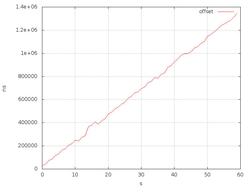
It is seen that the dependence is almost linear, for a second the counter on the device runs forward for more than twenty microseconds.
Then, the calculated error value was written to the offset adjustment register (offset):
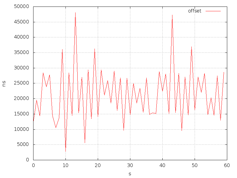
This graph also shows that, on average, an error of about 22 microseconds per second occurs. Using the adjustment using the offset is not very good, since this causes an abrupt change in the counter, and since this change occurs asynchronously on two instruments, this can lead to large errors when measuring the delay. It is better to use a smooth frequency adjustment, write to the register drift, such a value that the counter in the FPGA is adjusted to 22 microseconds per second.
For automatic adjustment implemented PI controller. For the integral component, we established a coefficient equal to 0.01 and for a proportional 0.05.
With it, the dependence of the mismatch on time looks like this:
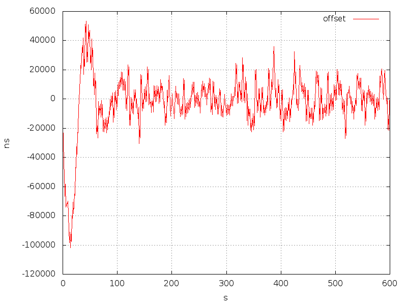
It can be seen that the mismatch is “noisy” and reaches 20 or more microseconds. This is not surprising, because a regular computer is used as a PTP server.
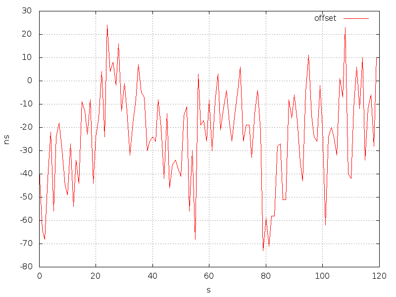
When we checked our implementation with the exact time server Metronom-50 , which implements hardware support for PTP, we received a mismatch of tens of nanoseconds, which is quite enough to correctly measure the delay in the asymmetric channel.
findings
If the delay in the channel under test is measured in milliseconds, then a regular computer with the ptpd daemon can be used as the PTP server. If the delay in the network is several microseconds, then we cannot do without a server with PTP hardware support.
Source: https://habr.com/ru/post/256867/
All Articles