BalanceBall. Self-balancing platform from A to Z
I am a student of the Physical Engineering Institute, the Faculty of Radio Engineering and Cybernetics, and as it should be for all the second-year students, in the spring semester it is necessary to do a project in computer science and microcontrollers. I decided to kill two birds with one stone and combined the two projects into one.
Long chose the theme of the project. From ideas there was a game similar to Guitar Hero, but the controller was your hands tapping the drum bits on the table. I also thought about creating an LED matrix that is controlled via Bluetooth from a computer with its own simple scripting language for writing animations. The ideas were interesting, but I still seemed something wrong. Then I accidentally stumbled upon this video and immediately set about trying to implement something like that. This is what I ended up with:
')
Who is interested in the process of creating this platform from designing details to writing computer vision, please under cat.
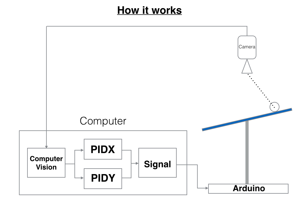
For several days I thought about what components this device should consist of and how they should interact with each other. In the end, came to this scheme:
1. The webcam transmits the image to the laptop
2. The ball coordinates are determined from the image.
3. The coordinates are fed to the input of the PID regulators (2 independent regulators in X and Y), and the regulators count the angles that the servos must turn
4. Corners are transmitted to the Arduino and set on servo drives.
You can portray it like this:
The first thing to decide is how the platform will look and move. On Youtube you can find a lot of videos with the implementation of this platform. After reviewing everything and reading a couple of publications on this topic, I decided that the platform would be fixed on the ball bearing, and would be tilted with the help of 2 servo drives mounted on a plate on which the whole structure would hold. At the very beginning of the video, the implementation of the platform mechanics is visible.
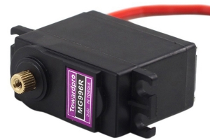
Servos decided to take stronger, to be sure that they can tilt the platform. Stopped on the TOWER PRO MG996R, with a moment of 9.4 kg / cm.
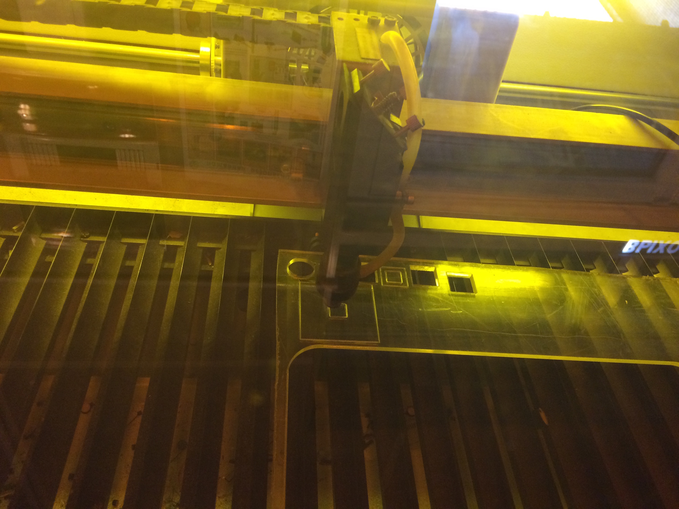
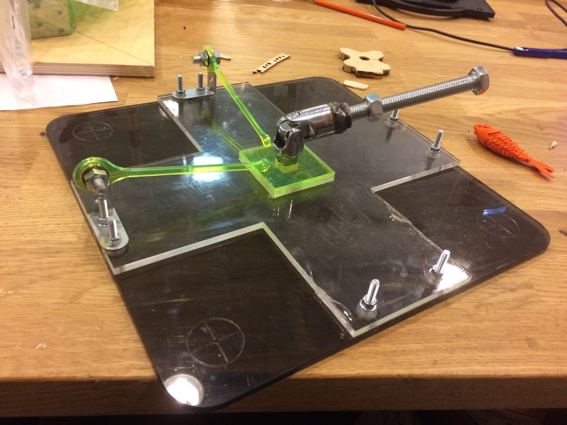
It was decided to cut out the platform, some fastenings from org glass on a laser cutter (good at our institute). Designed everything in SolidWorks. From the bottom, it was decided to attach a crosspiece to the platform, in order to attach both the ball bearing and corner brackets to it. Here are some photos of the creation process:

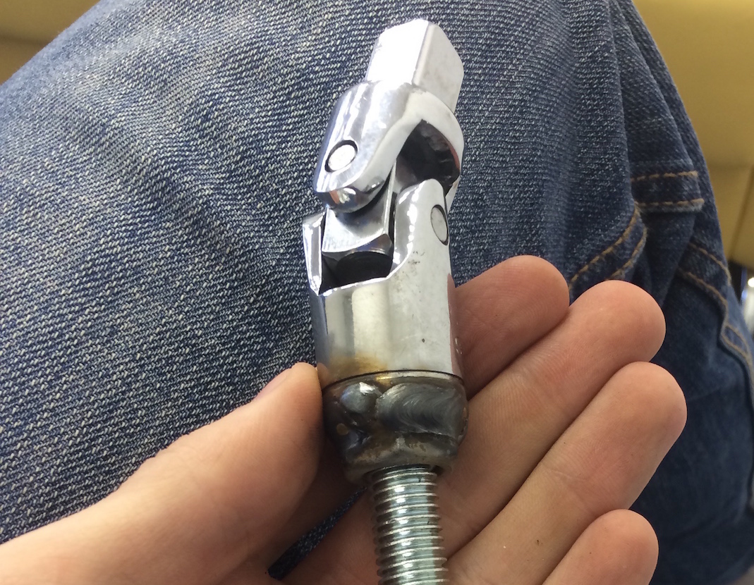
Began to look for ball bearings. Finding the right one was quite difficult, and, moreover, they were expensive. I suggested that instead of a ball, you can use a kardanchik, as on the keys. Bought kardanchik, a large bolt (it keeps everything) and nuts. By kardanchiku welded nut. Here's what happened:
I fixed everything on the bolts. Firstly, because if something is suddenly wrong, you can quickly unscrew the nuts and correct the error. Secondly, the design eventually turned out to be rather cumbersome, but since it is bolted, it is very easy to disassemble and compactly fit, for example, in a closet.
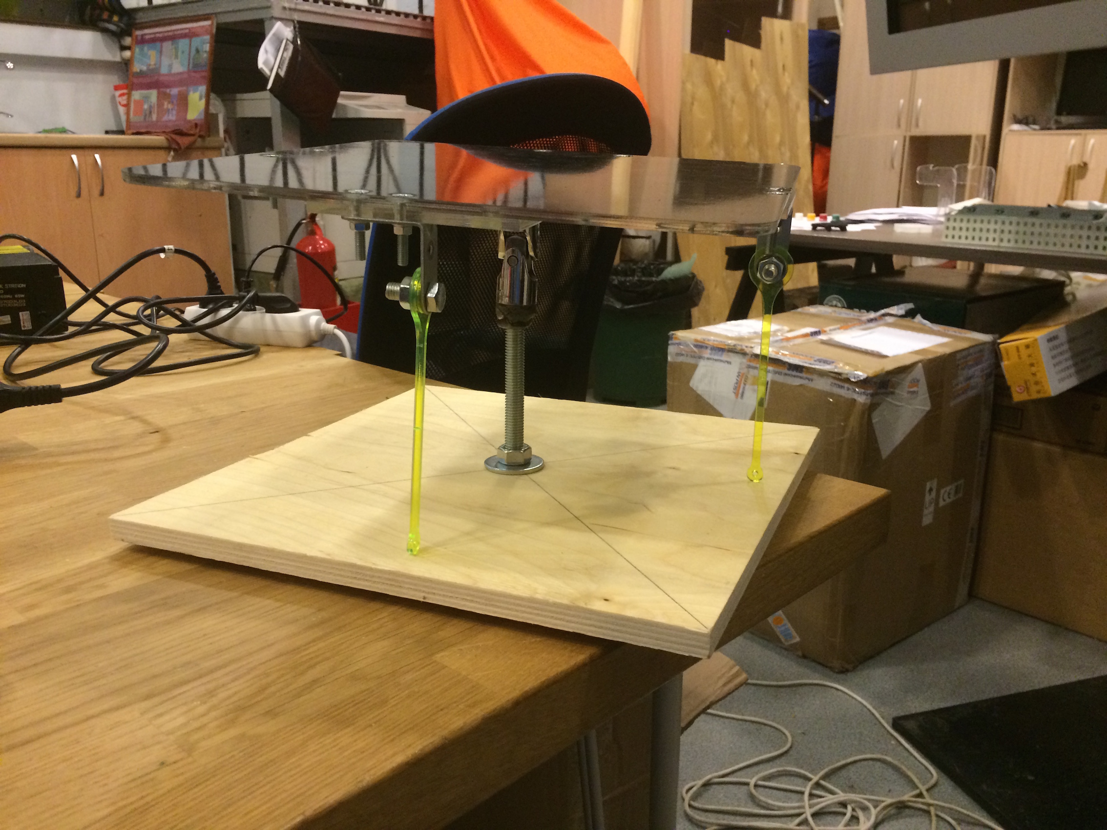
From plywood cut a square platform, which was all fastened. This is how the platform looked assembled:
Mounts for the camera decided to do later, in order to know exactly the height at which it should be raised.
The question arose: at what distance should servo drives be fixed from the center in order to achieve maximum deflection angles. The task was purely geometric, and after sitting with a pencil and paper for some time, it turned out to find this distance. Servos secured on plywood, pressing them to the plywood with a metal plate and bolts.
After complete assembly wrote a simple sketch for the Arduino, which tilted the platform at some angles.
Everything seemed to work, and it was hard to believe it.
Having played a little with the device, determined the angles when the platform is parallel to the floor, determined the maximum and minimum angles (± 13 degrees). It's time to write the code.
After long thinking about the structure of the program, I divided it into 4 modules:
1. Computer vision
2. Implementing a PID Regulator
3. Communication with Arduino on the serial port
4. Sketch for Arduino
I wrote everything in C ++. All code can be viewed in this repository .
Used OpenCV. Detection of the object decided to do in color. This article helped me a lot . The object detection algorithm can be decomposed into several steps:
1. Getting the frame from the camera
2. Conversion from RGB to HSV
3. Passing through a mask of a certain color (in my case, white)
4. The calculation of the moments of the image
5. Calculation of ball coordinates by moments
After reading on Wikipedia about PID regulators and looking at several ready-made implementations on github, I had no difficulty in implementing it in C ++. On Habré, I saw a lot of articles about PID-regulators, so I will not dwell on it.
I wrote all the code and ran it on OSX, so there were no problems with communication on the serial port. I sent the angles to the Arduino in the form of the line "[ANGLE_X]: [ANGLE_Y] $", where ANGLE_X and ANGLE_Y were respectively responsible for the tilt on its axis and varied from -100 to 100 (angles in percent). To send this line, I just wrote to a file like "/ dev/tty.usbmodem1421".
The wiring diagram looked like this:
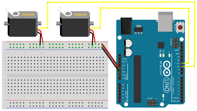
Arduino received a line on the serial port, parsed it and then put the right angles on the servos.
I spent about 2 months to create BalanceBall. The most difficult was the implementation of mechanics. PID set up experimentally. The plans include the creation of a mathematical model of the platform and the theoretical calculation of the coefficients of PID controllers.
Thank you all for your attention!
Project repository: github.com/karfly/balanceball
Folder with materials: goo.gl/bmkexm
PID controller
Discrete PID Controller
Color Detection & Object Tracking
Long chose the theme of the project. From ideas there was a game similar to Guitar Hero, but the controller was your hands tapping the drum bits on the table. I also thought about creating an LED matrix that is controlled via Bluetooth from a computer with its own simple scripting language for writing animations. The ideas were interesting, but I still seemed something wrong. Then I accidentally stumbled upon this video and immediately set about trying to implement something like that. This is what I ended up with:
')
Who is interested in the process of creating this platform from designing details to writing computer vision, please under cat.
Schematic diagram
For several days I thought about what components this device should consist of and how they should interact with each other. In the end, came to this scheme:
1. The webcam transmits the image to the laptop
2. The ball coordinates are determined from the image.
3. The coordinates are fed to the input of the PID regulators (2 independent regulators in X and Y), and the regulators count the angles that the servos must turn
4. Corners are transmitted to the Arduino and set on servo drives.
You can portray it like this:
Designing the mechanics of the platform
The first thing to decide is how the platform will look and move. On Youtube you can find a lot of videos with the implementation of this platform. After reviewing everything and reading a couple of publications on this topic, I decided that the platform would be fixed on the ball bearing, and would be tilted with the help of 2 servo drives mounted on a plate on which the whole structure would hold. At the very beginning of the video, the implementation of the platform mechanics is visible.
Servos decided to take stronger, to be sure that they can tilt the platform. Stopped on the TOWER PRO MG996R, with a moment of 9.4 kg / cm.
It was decided to cut out the platform, some fastenings from org glass on a laser cutter (good at our institute). Designed everything in SolidWorks. From the bottom, it was decided to attach a crosspiece to the platform, in order to attach both the ball bearing and corner brackets to it. Here are some photos of the creation process:
Began to look for ball bearings. Finding the right one was quite difficult, and, moreover, they were expensive. I suggested that instead of a ball, you can use a kardanchik, as on the keys. Bought kardanchik, a large bolt (it keeps everything) and nuts. By kardanchiku welded nut. Here's what happened:
Platform assembly
I fixed everything on the bolts. Firstly, because if something is suddenly wrong, you can quickly unscrew the nuts and correct the error. Secondly, the design eventually turned out to be rather cumbersome, but since it is bolted, it is very easy to disassemble and compactly fit, for example, in a closet.
From plywood cut a square platform, which was all fastened. This is how the platform looked assembled:
Mounts for the camera decided to do later, in order to know exactly the height at which it should be raised.
The question arose: at what distance should servo drives be fixed from the center in order to achieve maximum deflection angles. The task was purely geometric, and after sitting with a pencil and paper for some time, it turned out to find this distance. Servos secured on plywood, pressing them to the plywood with a metal plate and bolts.
First experience
After complete assembly wrote a simple sketch for the Arduino, which tilted the platform at some angles.
Everything seemed to work, and it was hard to believe it.
Having played a little with the device, determined the angles when the platform is parallel to the floor, determined the maximum and minimum angles (± 13 degrees). It's time to write the code.
Code writing
After long thinking about the structure of the program, I divided it into 4 modules:
1. Computer vision
2. Implementing a PID Regulator
3. Communication with Arduino on the serial port
4. Sketch for Arduino
I wrote everything in C ++. All code can be viewed in this repository .
Computer vision
Used OpenCV. Detection of the object decided to do in color. This article helped me a lot . The object detection algorithm can be decomposed into several steps:
1. Getting the frame from the camera
2. Conversion from RGB to HSV
3. Passing through a mask of a certain color (in my case, white)
4. The calculation of the moments of the image
5. Calculation of ball coordinates by moments
Implementation of the PID controller
After reading on Wikipedia about PID regulators and looking at several ready-made implementations on github, I had no difficulty in implementing it in C ++. On Habré, I saw a lot of articles about PID-regulators, so I will not dwell on it.
Communication with the Arduino on the serial port
I wrote all the code and ran it on OSX, so there were no problems with communication on the serial port. I sent the angles to the Arduino in the form of the line "[ANGLE_X]: [ANGLE_Y] $", where ANGLE_X and ANGLE_Y were respectively responsible for the tilt on its axis and varied from -100 to 100 (angles in percent). To send this line, I just wrote to a file like "/ dev/tty.usbmodem1421".
Sketch for Arduino
The wiring diagram looked like this:
Arduino received a line on the serial port, parsed it and then put the right angles on the servos.
Conclusion
I spent about 2 months to create BalanceBall. The most difficult was the implementation of mechanics. PID set up experimentally. The plans include the creation of a mathematical model of the platform and the theoretical calculation of the coefficients of PID controllers.
Thank you all for your attention!
Links
Project repository: github.com/karfly/balanceball
Folder with materials: goo.gl/bmkexm
PID controller
Discrete PID Controller
Color Detection & Object Tracking
Source: https://habr.com/ru/post/256815/
All Articles