Microcontroller Stapler
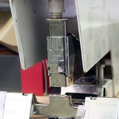
In the course of work as an “engineer of everything” in a printing house, one has to deal with the repair and upgrade of some tricky devices that are not commonly found in everyday life. One of my “favorites” is the brainchild of the gloomy Swedish genius, the electric Rapid 106 stapler. On the one hand, the oldest Rapid works for us from the beginning of the two thousandth, this is an indicator. On the other hand, there are enough problems with them. Some jokes are associated with specific electronics.
One day, the cup of patience was overflowing. At that time, I knew that Rapids were not good at network interference (and there are powerful frequency drives nearby), that one of them recently said: “WASTE!” And did not turn on anymore, and that the new device costs about 40 thousand rubles .
')
At first, I wanted to conduct reverse engineering of the native board. But in the process I decided that I absolutely did not like some of the technical solutions of the original. Yes, it is presumptuous, but the concept of “how to make it easier” was already taking shape in my head. Here are some features of the circuit design, it would seem, such a simple device as an electric stapler:
1. Four chips - two multivibrators, one counter, one set of triggers.
2. Under a hundred other items.
3. The power supply of microcircuits (for a minute, CMOS!) Is realized without galvanic isolation from the network.
4. There is a scheme of optical synchronization of the stapler with other equipment. You can use two staplers "in line". Never been used.
5. The electromagnet of the stapler is switched by the triac.
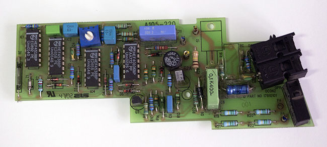
Native electronics stapler
Of these points, the willful decision of the first four is considered unnecessary. Formed a new principle of work:
1. To control the electromagnet uses a typical inclusion optocoupler MOC3052. Power triac and snubber (resistor and capacitor) migrate to the new circuit.
2. The control pulse on the optocoupler is given by the microcontroller.
Thus, we have ATTiny13A, which uses a comparator (to detect a mains voltage transition through zero), an ADC (a variable resistor on it sets the delay for outputting a shock pulse), one input (pedal-button) and one output (for issuing a pulse).
About cutting a sine wave
The triac, which controls the electromagnet, opens when the control voltage is applied, and closes when the mains voltage goes through zero (in the absence of the control voltage). You can open the triac either in zero or in some part of the half period. If we open in zero, then everything turns out very nicely and humanely, there is no interference from a sharp increase in voltage, but then we can operate only with a whole number of half-periods. The MOC306x optocoupler is equipped with a built-in zero detector, i.e., it turns on and off only at zero. In fact, combining it with a power triac, we get a solid-state AC relay.
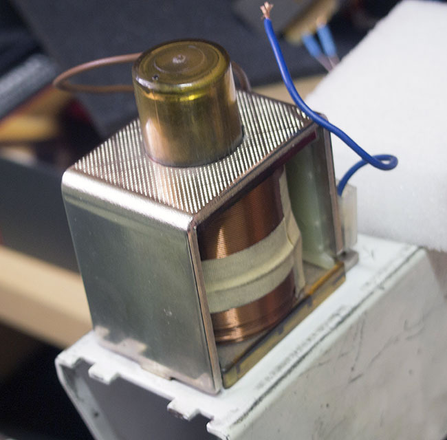
Actuator
But in our case, everything is worse. "Rapid" by the principle of control is not like a solid-state relay, but a dimmer. That is, at the command of the operator, our control unit must turn on the triac at a specific place in the half period. It will turn itself off when it reaches zero. The impact force depends in the end on how large the half cycle period is involved. So, we use the optocoupler MOC305x, in which there is no zero detection circuit.
Concrete
So, the operation algorithm is defined:
1. Pushing the pedal by the operator.
2. Determination of the triac inclusion. Depending on the position of the variable resistor (enabled by the divider between Vcc and GND, the average output at the ADC input), the delay (ms) is calculated, which lies in the specified range (selected by experience, 3-5 ms).
3. Detection of mains voltage zero (using a microcontroller comparator).
4. Testing the delay.
5. Issuance of a control pulse with a duration of 1 ms to the optocoupler.
Rakes were in point number 3. How to catch zero with a microcontroller? The simplest solution is to supply the mains voltage to one input of the comparator from the divider, to the second - a little more than zero (from the other divider). In this case, the galvanic isolation of the high- and low-voltage parts of the circuit is violated, and in real conditions we get disgusting noise immunity and accidental operation. On this inner Jedi said to me: "Solve the problem in the forehead." The solution is as follows: a small dirty transformer, issuing 9 VAC, is pulled out from somewhere. Two low-power diode bridges are placed on its exit. From one we take the measured pulsating voltage, on the other we put a capacitor and a stabilizer - this is the power supply of the microcontroller. And now, she, stability!
Implementation details
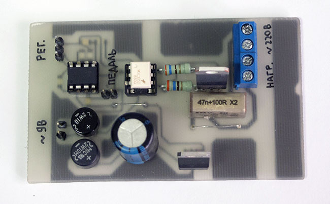
New board
Scheme - Eagle, layout - Sprint Layout. Firmware Development - Sublime Text (Sublime-AVR). Programming MK - ChipProg-40. ISP on the board is not divorced to simplify - debugging in the gland took a little time, with a maximum of a dozen distortions of the MK from the board to the programmer and back.
Firmware code
#include <avr/io.h> #include <util/delay.h> #define F_CPU 1200000UL // #define MINDELAY 3 #define MAXDELAY 5 // PB4. - . #define PEDAL PB4 // - PB3. - . #define FIRE PB3 void delaymsMod(unsigned char ms) // , _delay_ms . // . { for (unsigned char counter=0; counter<ms; counter++) { _delay_ms(1); } } unsigned char fireDelay(void) // . . . // , 0 // , , // , . . { // ACD - ACSR |= (1 << ACD); // 5 - ADLAR, . 8 ADCH // 0-1 - . 01 . ADC1 (PB2) ADMUX |= 0b00100001; // ADPS2-1-0 . 011 . 8 // 150 (1.2 / 8) ADCSRA |= (1 << ADPS1) | (1 << ADPS0); // ADCSRA |= (1 << ADEN); // ADCSRA |= (1 << ADSC); // , while (ADCSRA & (1 << ADSC)); // 8 unsigned char rawADC = ADCH; // ADCSRA &= ~(1 << ADEN); // return MINDELAY + rawADC * (MAXDELAY - MINDELAY) / 255; } void waitForZero(void) // . . . { ACSR &= ~(1 << ACD); _delay_ms(1); while ((ACSR & 0b00100000) == 0b00100000); ACSR |= (1 << ACD); } unsigned char pedal(void) // . . . { unsigned char pressed = 0; // // , unsigned char pressedTime = 100; if (PINB & (1 << PEDAL)) // , , 1 { pressed = 1; for (unsigned char counter=0; counter < pressedTime; counter++) { // , // , 0 - if ( !(PINB & (1 << PEDAL))) { pressed = 0; } _delay_ms(1); } } return pressed; } void fire(void) // 1 { PORTB |= (1 << FIRE); _delay_ms(1); PORTB &= ~(1 << FIRE); } void setup(void) { // DDRB=0b00001000; } int main(void) { setup(); while (1) { if (pedal()) { waitForZero(); delaymsMod(fireDelay()); fire(); while(pedal()); } } return -1; // } SMD resistors (1206) and capacitors (0805) in the low-voltage part of the circuit were used to acquire additional installation skills. Board manufacturing techniques:
1. A piece of some PCB. Cleaning with a hard dish cloth and Pemolux.
2. Film photoresist (Ordyl Alpha 350). Prikatka GMP laminator (120 degrees, min. Speed).
3. Photomask (transparent film, Oki 9655 printer).
4. Highlights a 20-watt UV savings (6 minutes).
5. Remover excess (potash).
6. Etching (ferric chloride, water bath, periodic exposure with a soft brush).
7. Drilling, tinning, sealing, testing.
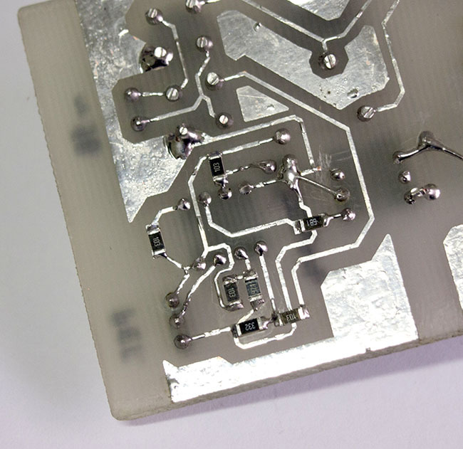
SMD-on-the-knee and wiring error correction
Total
Spent a lot of time. Two weeks passed from idea to implementation, was engaged in the project in “free time”. But now there is a simple, clear, cheap and easily repeatable control unit stapler. Received additional skill - the use of optocouplers and triacs for load control.
All developments - on githabe.
UPD. Added video. Filmed on a tea-bag with a bad camera, but it gives a general idea. The first two blows are “idle” because of the almost complete death of the stepping head, it was used to debug the general concept.
Source: https://habr.com/ru/post/256763/
All Articles