We are switching from STM32 to the Russian K1986BE92QI microcontroller. Practical application: Generate and reproduce sound. Part three: generate a sine wave. A simple look at DMA + first acquaintance with timers
Introduction
In the previous article, I talked about my first encounter with DMA. In it, we did a bunch of DMA + SysTick. The article turned out to be very specific and complex, in view of the inexperienced crooked approach. Having gained experience, in this article I will talk about a much simpler and more understandable way of working with DMA.Main aspects
From the previous article, we learned that in order to run DMA, you need:- Send a clock signal to the DMA module.
- Fill out the DMA operation control structure.
- Set up DMA.
- To configure the channel.
- Enable transfer.
- At the end of the transfer "restore" (overwrite) the structure.
Setting up the structure of the DMA, the DMA itself and the channel-bundle with a timer
As we remember, each channel has its own control structure (in our case, there are as many as two). We configure them as described in the previous article. The resulting settings will be saved in two variables. From these variables we will later restore our structures.Setting up structures.
As you can see, I allocated memory for 32 primary and 32 alternative structures, which in total will give a kilobyte of memory in RAM. I went to this step, so as not to suffer with offsets. In the future, it will be easy to make an offset and leave 2 structures. Next you need to fill these structures.//------------------------------------------------- // . //------------------------------------------------- #define dst_src (3<<30) // - 16 (). #define src_inc (1<<26) // 16 . #define src_size (1<<24) // 16 . #define dst_size (1<<28) // 16 . . #define n_minus_1 (49<<4) //50 (-1) DMA. #define cycle_ctrl (3<<0) //-. struct DAC_ST { uint32_t Destination_end_pointer; // . uint32_t Source_end_pointer; // uint32_t channel_cfg; // . uint32_t NULL; // . } __align(1024) DAC_ST; // 1024 . struct DAC_ST DAC_ST_ADC[32+32]; // . /// = 16 , / = 16 , , 50 , -. uint32_t DMA_DAC_InitST_PR = dst_src|src_inc|src_size|dst_size|n_minus_1|cycle_ctrl; uint32_t DMA_DAC_InitST_ALT = dst_src|src_inc|src_size|dst_size|n_minus_1|cycle_ctrl; Filling structures
As you can see, the difference between these two structures is only in the final addresses of the data source. In the primary we specify the center of the array (the transfer will be from the beginning to the middle), and the secondary end (the transfer from the middle to the end). // . DAC_ST_ADC[10-1].Destination_end_pointer = (uint32_t)C_4 + (sizeof(C_4))/2 - 1; // (C_4 - 100 ). DAC_ST_ADC[10-1].Source_end_pointer = (uint32_t)&(DAC->DAC2_DATA); // ( ) ( DAC). DAC_ST_ADC[10-1].channel_cfg = (uint32_t)(DMA_DAC_InitST_PR); // . DAC_ST_ADC[10-1].NULL = (uint32_t)0; // . // . DAC_ST_ADC[10-1+32].Destination_end_pointer = (uint32_t)C_4 + sizeof(C_4) - 1; // (C_4 - 100 ). DAC_ST_ADC[10-1+32].Source_end_pointer = (uint32_t)&(DAC->DAC2_DATA); // ( ) ( DAC). DAC_ST_ADC[10-1+32].channel_cfg = (uint32_t)(DMA_DAC_InitST_ALT); // . DAC_ST_ADC[10-1+32].NULL = (uint32_t)0; // . Now configure the DMA.
Well, it remains only to configure the channel. But which one? We can refer to the table in the previous article. But. After writing the previous article I was informed about my mistake. The fact is that the table is not quite correct. #define CFG_master_enable (1<<0)// . #define PCLK_EN_DMA (1<<5)// DMA. // DMA. RST_CLK->PER_CLOCK|=PCLK_EN_DMA; // DMA. DMA->CTRL_BASE_PTR = (uint32_t)&DAC_ST_ADC; // . DMA->CFG = CFG_master_enable; // DMA. A more accurate table looks like this.
The table was given to me at the official forum, but it is also in the official library. We will use timer 1. => our channel is the tenth. /** @defgroup DMA_valid_channels DMA valid channels * @{ */ #define DMA_Channel_UART1_TX ((uint8_t)(0)) #define DMA_Channel_UART1_RX ((uint8_t)(1)) #define DMA_Channel_UART2_TX ((uint8_t)(2)) #define DMA_Channel_UART2_RX ((uint8_t)(3)) #define DMA_Channel_SSP1_TX ((uint8_t)(4)) #define DMA_Channel_SSP1_RX ((uint8_t)(5)) #define DMA_Channel_SSP2_TX ((uint8_t)(6)) #define DMA_Channel_SSP2_RX ((uint8_t)(7)) #define DMA_Channel_ADC1 ((uint8_t)(8)) #define DMA_Channel_ADC2 ((uint8_t)(9)) #define DMA_Channel_TIM1 ((uint8_t)(10)) #define DMA_Channel_TIM2 ((uint8_t)(11)) #define DMA_Channel_TIM3 ((uint8_t)(12)) #define DMA_Channel_SW1 ((uint8_t)(13)) #define DMA_Channel_SW2 ((uint8_t)(14)) #define DMA_Channel_SW3 ((uint8_t)(15)) #define DMA_Channel_SW4 ((uint8_t)(16)) #define DMA_Channel_SW5 ((uint8_t)(17)) #define DMA_Channel_SW6 ((uint8_t)(18)) #define DMA_Channel_SW7 ((uint8_t)(19)) #define DMA_Channel_SW8 ((uint8_t)(20)) #define DMA_Channel_SW9 ((uint8_t)(21)) #define DMA_Channel_SW10 ((uint8_t)(22)) #define DMA_Channel_SW11 ((uint8_t)(23)) #define DMA_Channel_SW12 ((uint8_t)(24)) #define DMA_Channel_SW13 ((uint8_t)(25)) #define DMA_Channel_SW14 ((uint8_t)(26)) #define DMA_Channel_SW15 ((uint8_t)(27)) #define DMA_Channel_SW16 ((uint8_t)(28)) #define DMA_Channel_SW17 ((uint8_t)(29)) #define DMA_Channel_SW18 ((uint8_t)(30)) #define DMA_Channel_SW19 ((uint8_t)(31)) #define IS_DMA_CHANNEL(CHANNEL) (CHANNEL <= (DMA_Channels_Number - 1)) /** @} */ /* End of group DMA_valid_channels */ // . DMA->CHNL_ENABLE_SET = 1<<10; // 10 . We got the following function.
//------------------------------------------------- // DMA DAC. //------------------------------------------------- void DMA_to_DAC_and_TIM1 (void) { // . DAC_ST_ADC[10-1].Destination_end_pointer = (uint32_t)C_4 + (sizeof(C_4))/2 - 1; // (C_4 - 100 ). DAC_ST_ADC[10-1].Source_end_pointer = (uint32_t)&(DAC->DAC2_DATA); // ( ) ( DAC). DAC_ST_ADC[10-1].channel_cfg = (uint32_t)(DMA_DAC_InitST_PR); // . DAC_ST_ADC[10-1].NULL = (uint32_t)0; // . // . DAC_ST_ADC[10-1+32].Destination_end_pointer = (uint32_t)C_4 + sizeof(C_4) - 1; // (C_4 - 100 ). DAC_ST_ADC[10-1+32].Source_end_pointer = (uint32_t)&(DAC->DAC2_DATA); // ( ) ( DAC). DAC_ST_ADC[10-1+32].channel_cfg = (uint32_t)(DMA_DAC_InitST_ALT); // . DAC_ST_ADC[10-1+32].NULL = (uint32_t)0; // . // DMA. RST_CLK->PER_CLOCK|=PCLK_EN_DMA; // DMA. DMA->CTRL_BASE_PTR = (uint32_t)&DAC_ST_ADC; // . DMA->CFG = CFG_master_enable; // DMA. // . DMA->CHNL_ENABLE_SET = 1<<10; // 10 . } Introducing the timer
First of all, the timer must be turned on (zakattirovat).
And now actually, it is worth starting to understand. All three timers have the same features. At least at first glance. Each timer has a very rich functionality => many registers. But they are very easy to understand. I did not encounter any rake in the way of studying the work of timers. We remember that we set up DMA so that the timer can control it. For this purpose, it will be enough for us to just wait a certain amount of time and transmit the next portion of data. The timer has 4 channels of "comparison" and the main counter. It will be enough for us to use the main counter.
#define PER_CLOCK_TIMER1_ONCLK (1<<14) // 1. RST_CLK->PER_CLOCK |= PER_CLOCK_TIMER1_ONCLK; // . Take a look at the main timer register.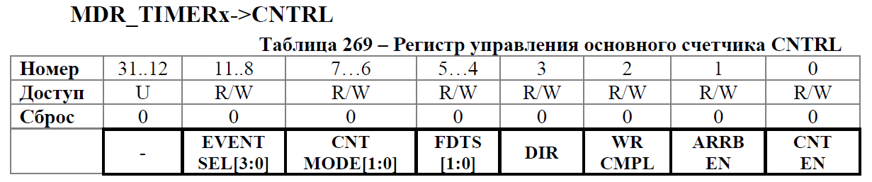

Here we should allow the timer to work.
As a test, we will consider up to 0xFFFF (later we will deal with time intervals). By default, the account goes from 0.
#define CNTRL_CNT_EN (1<<0) // . TIMER1->CNTRL |= CNTRL_CNT_EN; // , = . TIMER1->ARR = 0xFFFF; // ... Next you need to associate our timer with DMA. As the event for which the transmission will occur, we select CNT == ARR in timer 1. This is a simple comparison of the current value of the CNT timer with the number in the ARR register.For this there is a register DMA_RE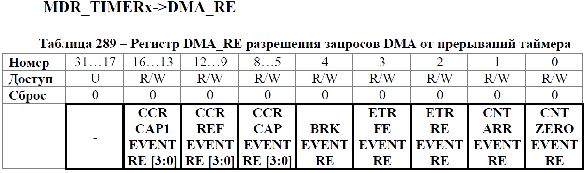 Here we need to choose a link to achieve the desired value by the counter.
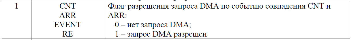
One could say that the setup is complete, BUT. Now our timer is clocked on the HCLK frequency, which without a divider = 8 MHz. Our value of 0xFFFF will be reached instantly. And we will not be able to trace our transmission. To solve this problem, we must include a pre-divider. Here we need to choose a link to achieve the desired value by the counter.
For these purposes, the register RST_CLK-> TIM_CLOCK in the clocking block is used.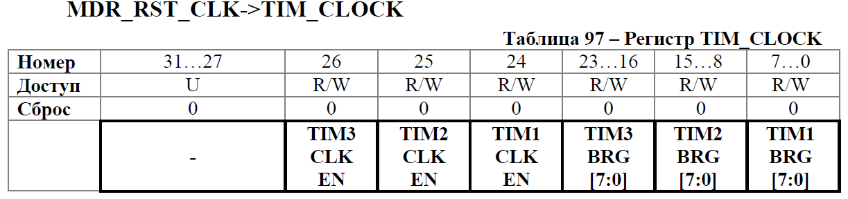
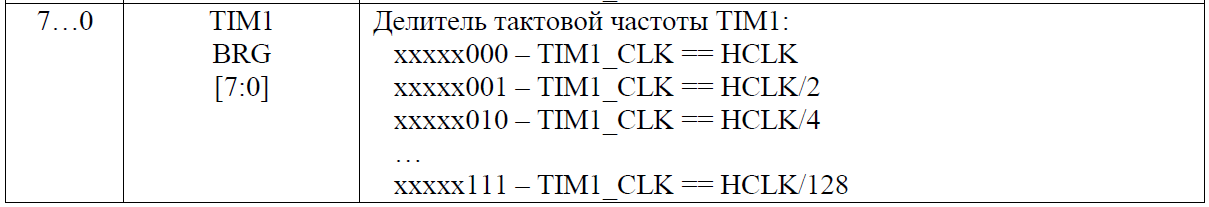 For the sample, I turned on the biggest divider. Also here it is necessary and to give a signal of clocking on the timer. So that the timer starts counting from the HCLK through the pre divider.

 For the sample, I turned on the biggest divider. Also here it is necessary and to give a signal of clocking on the timer. So that the timer starts counting from the HCLK through the pre divider.
As a result, we get such a function.
Now, if we turn on our example, we will observe how the change in the value of the voltage value register in DAC2 occurs with an interval of about a second. Well, the first stage is over. The truth is that the process will be interrupted in the middle of our array. The fact is that the timer can only re-enable the transmission. But as soon as we transferred half the array, we “used up” the first structure. Now it is necessary to restore it. For this we will use the second timer. Many will be asked, “Why not interrupt the transfer from DMA or transfer half of the array?”. The fact is that in our DMA can only generate an interrupt at the end of the transfer. There is no possibility to cause an interruption after the passage of the middle. But here it is not so simple. Recall that we pass not everything, but in parts. Our DMA does not understand this. An interrupt is generated while the DMA is idle. In other words, DMA does not understand that not the entire data packet is transmitted, but only one element of the array. This fact makes the use of DMA interrupts unsuitable for our task. #define PER_CLOCK_TIMER1_ONCLK (1<<14) // 1. #define TIM_CLOCK_TIM1_CLK_EN (1<<24) // 1. #define SHARE_HCLK_TIMER 7 // HCLK ... (0 = , 1 = /2, 2 = /4). #define TIM_CLOCK_TIM1_BRG (SHARE_HCLK_TIMER<<0) // 1 SHARE_HCLK_TIMER. #define CNTRL_CNT_EN (1<<0) // . #define DMA_RE_CNT_ARR_EVENT_RE (1<<1) // DMA CNT == ARR; void Init_TIMER1_to_DMA_and_DAC2 (void) { RST_CLK->PER_CLOCK |= PER_CLOCK_TIMER1_ONCLK; // . TIMER1->CNTRL |= CNTRL_CNT_EN; // , = . TIMER1->ARR = 0xFFFF; // ... TIMER1->DMA_RE |= DMA_RE_CNT_ARR_EVENT_RE; // "" DMA. RST_CLK->TIM_CLOCK |= TIM_CLOCK_TIM1_CLK_EN|TIM_CLOCK_TIM1_BRG; // . } We configure timers for generation of a sinusoid
As I said, in order to “restore” the structure, we must configure the next (second) timer to interrupt after passing half of the half of the array (1/4 of the entire array). Why exactly one fourth - I will explain further. But before that, reconfigure the first timer. We need to decide on the speed of the "kicks" DMA. We look. The controller clocks with a frequency of 8 MHz. Our array contains 100 elements. The frequency of the notes to the first octave, as we remember, is 261.63 Hz. The capacity of the account register is 0xFFFF (up to this value, the counter can read). We divide 8,000,000 Hz / 261.63 Hz / 100 notes = once in 305 cycles to "kick" the DMA. This is much less than the maximum value of the timer comparison register. Thus, we do not have to use a pre divider.Serving clocking on both timers.
After switching on the timer clocking (total block), it sometimes happens that the timer starts its work according to previously configured parameters. Because of this, even before their settings, there are various glitches. To prevent this, you need to disable the clocking signal of the counting block (so that the timer does not have time to count up to any value from which it will cause, for example, an interrupt). RST_CLK->PER_CLOCK |= PER_CLOCK_TIMER1_ONCLK|PER_CLOCK_TIMER2_ONCLK; // 1 2. Disable clocking counting unit.
RST_CLK->TIM_CLOCK = 0; // . Next, we specify the period of appeal to the DMA and allow it.
Now we set up timer 2. For simplicity, we will also clock it without a divider. We also decide how often to cause an interrupt. Due to the fact that we clock both timers from the same source, we cannot update the value of the structure at the very moment when the last element of the first structure was transmitted. Because when the DMA makes an attempt to transfer the element that follows the last of the first structure, it will come across its end and automatically switch to the alternative one. Thus, it is necessary to wait until the DMA decides that the primary structure is “exhausted” and begins to transmit from the alternative. To do this, just wait for the transfer of at least one packet from the alternative structure. Then you can fill the primary again. The same should be done with the alternative. When the transmissions end in it, you need to wait until the DMA transfers at least 1 packet from the primary one, after which you can overwrite the alternative one. We transfer 100 items. 50 in each structure. We could cause an interruption along with the fiftieth transmission, but for the reasons described above, we need to wait for at least the 51st transmission. In order not to suffer with offsets, let's make a check of both structure every 25 gears. // 8000000 /261.63/100 = 305. TIMER1->ARR = 305; // ... TIMER1->DMA_RE |= DMA_RE_CNT_ARR_EVENT_RE; // DMA. Thus, the period of our timer will be 305 * 25.
TIMER2->ARR = 305*25; // . Something about interruptions
In order for an interrupt to occur when the timer reaches the desired value, it is necessary.- Enable event interruption: the counter reaches the desired value in the TIMERx-> IE register
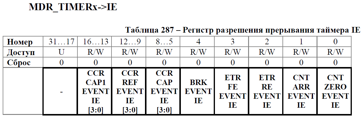
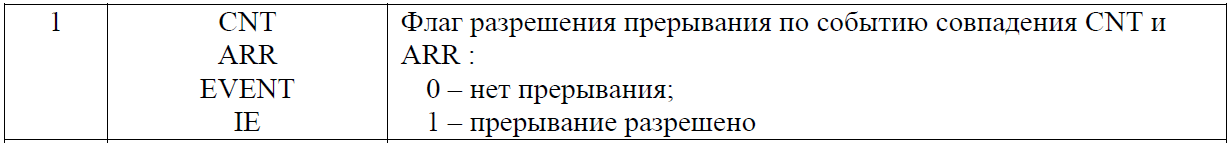
#define TIMERx_IE_CNT_ARR_EVENT_IE (1<<1) //: CNT ARR. TIMER2->IE = TIMERx_IE_CNT_ARR_EVENT_IE; // . - Clear flag of any interrupts TIMERy-> STATUSThe fact is that after the interrupt is enabled, its flag is automatically set. In order not to go to the interrupt immediately after setting it is necessary to reset it.
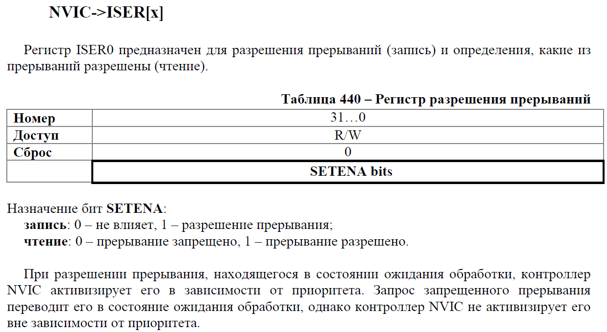
TIMER2->STATUS=0; // . - Enable timer interrupt on the NVIC interrupt controller.A separate article is worth highlighting on this controller, but in this article we will limit ourselves to the following information base: in order for the controller to “notice” that the timer requires an interrupt, you need to enable this interrupt itself. This is done in the register NVIC-> ISER [0].
 We need to find out which number has a timer interrupt. To do this, go to the startup file and look for the vector with the desired name.
DCD Timer2_IRQHandler ; IRQ15NVIC->ISER[0] = 1<<15; // 2. - You need to create an interrupt handler function and reset the interrupt flag in it (this is done manually).
void Timer2_IRQHandler (void) // . TIMER2->STATUS=0; }


 We need to find out which number has a timer interrupt. To do this, go to the startup file and look for the vector with the desired name.
We finish setting the timers.
After we have specified the parameters of the timers, we must allow them to work and send a clock signal to the counter.
#define CNTRL_CNT_EN (1<<0) // . #define TIM_CLOCK_TIM1_CLK_EN (1<<24) // 1. #define TIM_CLOCK_TIM2_CLK_EN (1<<25) // 2. TIMER1->CNTRL = CNTRL_CNT_EN; // . TIMER2->CNTRL = CNTRL_CNT_EN; RST_CLK->TIM_CLOCK = TIM_CLOCK_TIM1_CLK_EN|TIM_CLOCK_TIM2_CLK_EN; // . The result of the configuration was the function.
#define PER_CLOCK_TIMER1_ONCLK (1<<14) // 1. #define PER_CLOCK_TIMER2_ONCLK (1<<15) // 1. #define TIM_CLOCK_TIM1_CLK_EN (1<<24) // 1. #define SHARE_HCLK_TIMER1 7 // HCLK ... (0 = , 1 = /2, 2 = /4). #define TIM_CLOCK_TIM1_BRG (SHARE_HCLK_TIMER1<<0) // 1 SHARE_HCLK_TIMER. #define CNTRL_CNT_EN (1<<0) // . #define CNTRL_EVENT_SEL (1<<8) // : CNT == ARR; #define DMA_RE_CNT_ARR_EVENT_RE (1<<1) // DMA CNT == ARR; #define IE_CNT_ARR_EVENT_IE (1<<1) // CNT == ARR; #define TIM_CLOCK_TIM2_CLK_EN (1<<25) // 2. #define SHARE_HCLK_TIMER2 7 // HCLK ... (0 = , 1 = /2, 2 = /4). #define TIM_CLOCK_TIM2_BRG (SHARE_HCLK_TIMER2<<8)// 1 SHARE_HCLK_TIMER. #define CH1_CNTRL_CAP_nPWM_Z (1<<15) //: "". #define CH1_CNTRL_CHPSC_8 (3<<6) //: 8. #define CHy_CNTRL2_CCR1_EN (1<<2) //: 1. #define TIMERx_IE_CNT_ARR_EVENT_IE (1<<1) //: CNT ARR. void Init_TIMER1_to_DMA_and_DAC2 (void) { RST_CLK->PER_CLOCK |= PER_CLOCK_TIMER1_ONCLK|PER_CLOCK_TIMER2_ONCLK; // 1 2. RST_CLK->TIM_CLOCK = 0; // . // 8000000 /261.63/100 = 305. TIMER1->ARR = 305; // ... TIMER1->DMA_RE |= DMA_RE_CNT_ARR_EVENT_RE; // DMA. TIMER2->ARR = 305*25; // . TIMER2->IE = TIMERx_IE_CNT_ARR_EVENT_IE; // . TIMER2->STATUS=0; // . NVIC->ISER[0] = 1<<15; // 2. TIMER1->CNTRL = CNTRL_CNT_EN; // . TIMER2->CNTRL = CNTRL_CNT_EN; RST_CLK->TIM_CLOCK = TIM_CLOCK_TIM1_CLK_EN|TIM_CLOCK_TIM2_CLK_EN; // . } We write the function of changing structures.
We described the interrupt. It remains only to check in it: if the primary structure has ended and at least 1 block from the alternative structure has been transferred, overwrite the primary one. Same with the secondary. Do not forget also that after the transfer of the first structure - DMA blocks the channel. It is necessary to again allow his work so that the “kicks” from timer 1 continue to pass.Interrupt
The code of the main function from the last example is changed only by turning on a new function and turning off SysTick. #define ST_Play_P (DAC_ST_ADC[10-1].channel_cfg & (1023<<4)) // . #define ST_Play_ALT (DAC_ST_ADC[10-1+32].channel_cfg & (1023<<4)) // . void Timer2_IRQHandler (void) // . { if ((ST_Play_P == 0) && (ST_Play_ALT <= (48<<4))) // - 2-. DAC_ST_ADC[10-1].channel_cfg = (uint32_t)(DMA_DAC_InitST_PR); if ((ST_Play_ALT == 0) && (ST_Play_P <= (48<<4))) DAC_ST_ADC[10-1+32].channel_cfg = (uint32_t)(DMA_DAC_InitST_ALT); DMA->CHNL_ENABLE_SET = 1<<10; TIMER2->STATUS=0; } Here he is.
Running the program, we get the following picture at the output. int main (void) { HSE_Clock_ON(); // HSE . HSE_Clock_OffPLL(); // "" HSE . Buzzer_out_DAC_init(); // . DAC_Init(); // . DMA_to_DAC_and_TIM1(); // DMA DAC2 1. Init_TIMER1_to_DMA_and_DAC2(); // 1. while (1) { } }  Download the sound here . Download the example code here .
About errors
Long tormented with the selection of the moment for the change of structures. All the time, something like this came out.

Summarize
We managed to take another look at DMA, start enjoying its benefits. In the next article we will consolidate our skills and create a semblance of a music box, and after - the player.List of previous articles.
- 1. We turn from STM32F103 to K1986BE92QI. Or the first acquaintance with the Russian microcontroller.
- 2. We are switching from STM32 to the Russian K1986BE92QI microcontroller. Setup project in keil and flashing LED.
- 3. We are switching from STM32 to the Russian K1986BE92QI microcontroller. System Timer (SysTick).
- 4. We are switching from STM32 to the Russian K1986BE92QI microcontroller. Setting the clock frequency.
- 5. We are switching from STM32 to the Russian K1986BE92QI microcontroller. Practical application: Generate and reproduce sound. Part one: we generate a square and sinusoidal signal. Mastering the DAC (DAC).
- 6. We are switching from STM32 to the Russian K1986BE92QI microcontroller. Practical application: Generate and reproduce sound. Part two: generate a sinusoidal signal. Mastering DMA.
')
Source: https://habr.com/ru/post/256577/
All Articles