PCB assembly: quick start from scratch
If you remember my previous post , there was a desire to understand what and how you can add to the model I liked to make DIY forever. Many thanks to users of UseTi , Phmphx , lomalkin and especially n4k4m1sh1 , who shared interesting ideas on this topic in the comments. It is clear that for the goals we need two skills, one of which is the installation of a printed circuit board. So today we will solder from scratch.

From the shelf of the children's store was taken another set, specifically this one .
')
So, we are testing the “Young Electronics Engineer Set”. Will it be possible with his help to assemble working structures from scratch without having preliminary skills, as we did with the mechanical model before?
The set already has everything to quickly complete the assembly:
Those. there is something to solder, what to solder and, which is important - how to check the components and the already prepared circuit.
Also, the kit includes two brochures:
1. Methodical manual, which contains general information about the devices, parts and the process of soldering.
2. Instructions for collecting two members of a set of devices and the subsequent configuration of one of them.
The brochures are good, but if you remember, I liked the instructions for the robot, where there were no words - only the images + step by step the assembly was written. The instructions for this set of step-by-step instructions are not. In some ways, this is good, because if you are guided by these two brochures, you want to, you don't want, you have to read and understand everything first, and only then act - that is, they teach you to think systematically. But there is a little lack of dynamics, and, it seems to me, the children may also miss more than me. Therefore, if you collect something like that, I hope this post will save you a lot of time.
What is not in the set, but will be needed or may be needed:
1. Tweezers. We took a manicure.
2. Battery "Krona" on 9V
3. Phillips screwdriver - in one of the schemes there is a terminal. Tighten the wires in it will turn clockwise screwdriver.
4. A “third hand” soldering device - this is what you can do without, although it is constantly mentioned in the instructions and the brochure. Of course, it would be more convenient with her, but if you just collect all the parts on the board and then turn it over, then both the boards included in the kit will be relatively stable and will be soldered in principle conveniently and without additional devices.
5. Magnifier
6. Desoldering pump
7. Goggles and respirator
8. Soldering Iron Stand
9. Fan \ exhaust
Of the entire list, it will be very tight without the first two items. At this time, the robot from the previous post became a support for the soldering iron. The rest for mounting two small boards would really be superfluous.
But it would be useful to remind you that when soldering, tin pairs are released that are not very good for health. Actually the soldering of the two included circuits took me no more than 10 minutes and I did not poplohe. However, a small fan, driving away smoke to the side, or at least an open window is a standard and very good practice. In addition, after soldering, you need to wash your hands. You should also take care of your eyes - a leg of a part bit off with a nipper can fly off or a drop of hot tin can fly off during the soldering process (although we did not fly away). Therefore, wear safety glasses. Take care of yourself!
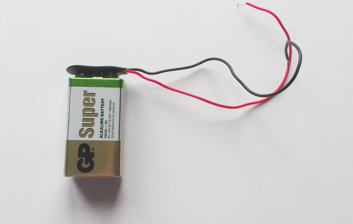
To begin with, all we need is a separately purchased “Krona” battery. The set has a connector for it, which, according to the instructions, must be soldered into the first circuit. My advice: do not do it, leave it like that and use it in both schemes - for testing the first one and for setting up the second one.
Devices that we collect, consume some kind of insane amount of mA \ hour.
If we are talking about an electrical circuit, then our resources and how we quickly spend them are measured in A \ h (Ampere per hour, mAh). Capacity typical "Krona" (according to the passport):
625 mA · h ≈ 0.5 A · h
The first device, the Chameleon, consumes up to 200 mAh. Therefore, our Krona this scheme is enough for:
625mAh / 200mA = 3.125 hours.
so it is recommended to use it only to check the operation of the circuit. A good output would be a 12 volt battery with a capacity of at least 0.5 Ah.
It would be cool to be able to solder one of these connectors onto the boards, and then plug in such a laboratory power supply into it . But under one of the available connectors on the board there are no suitable holes. Therefore, we can not connect the power supply yet.
There is such an anecdote: a man bought a plane and a magazine with the description “How to make a dead loop”. Following the instructions, I got on the plane, took off, started to make a dead loop - everything works out. Turns the page, and there: "... exit from the dead loop, read the next issue."
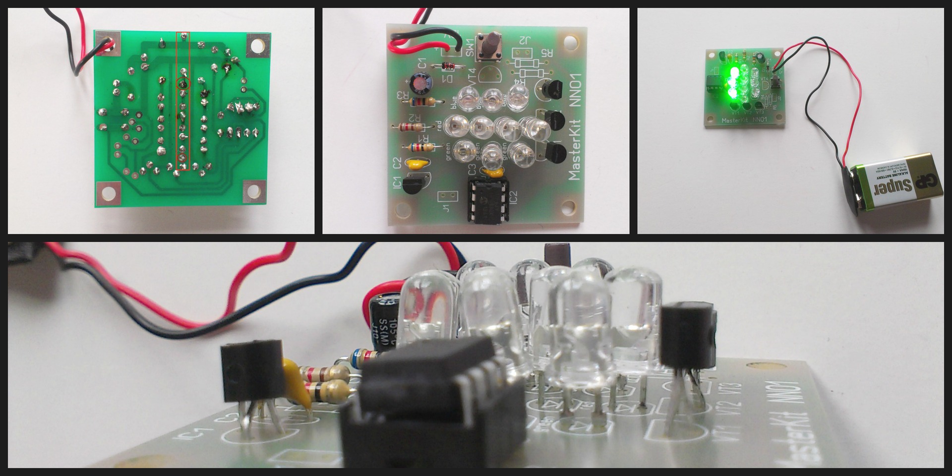
You can talk a lot about the culture of soldering and that this is a whole art. One thing will remain the same: if you do something for the first time and on the book, then at first it may not work. Here is our first board, a set of "Chameleon", or rather what came of it. What mistakes were made?
1. Soldering technology is broken, as a result - non-soldered contacts, which are better to be soldered and soldered again (without mixing up the polarity!)
2. Violation of the work technology: each part was soldered in turn. Below you will see how much more profitable in this plan is to listen to the instructions and first collect all the details and then fix them.
Result: the parts stand beautifully in the curve and in the cavity, and of the three diode chains, only one of them caught fire.
Possible solution: drop all the parts and solder again.
Positive moment: you can always find. In this case, we do not have “parasitic jumpers” anywhere. True, it is enough to remove them simply in any case: just hold the tip of the soldering iron and separate the contacts that have been soldered together.
So, the first scheme did not work out for us due to the violation of the soldering technology, therefore we will immediately discuss this simple and really pleasant moment.
The brochure clearly shows and tells how to solder, but, unfortunately, it did not help me much, because it says “how to”, but I would like to understand the technique itself.
Perhaps the best recommendation that was found was in this post . I will give it entirely:
In addition, I can recommend an illustrated comic , translated by the atarity user .
Also, from time to time a deposit is formed on the soldering iron tip and needs to be cleaned. To do this, the industry uses special cellulose sponges, which are necessarily moistened with water. In our case, the carbon can be removed simply by shaking it off mechanically - for example, by the blunt side of the knife.
After the first device was unjustly ruined by us, an understanding of how to build the process more effectively appeared. I hope this step-by-step instruction will help you just as quickly assemble your own set.
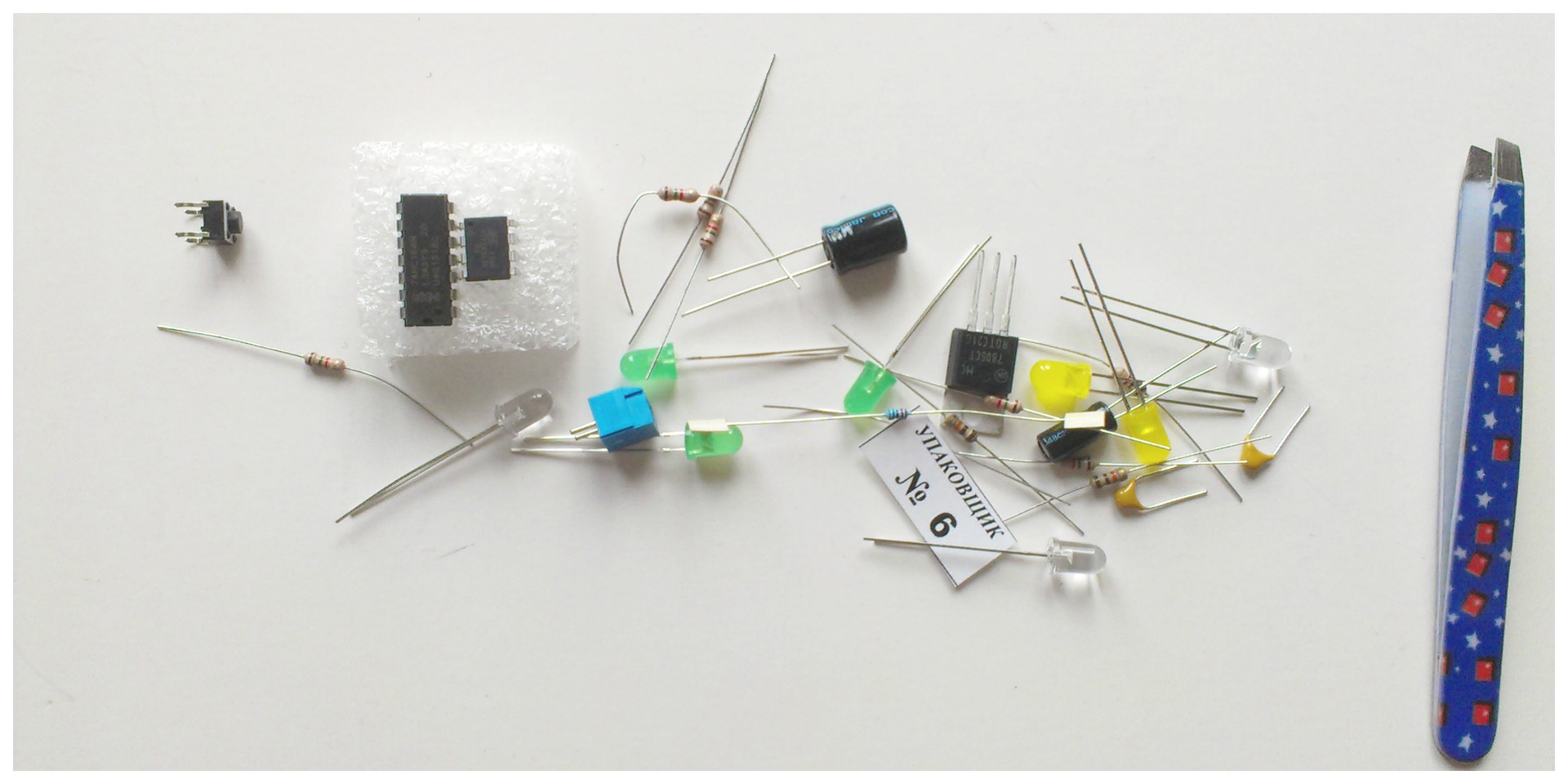
So, we have a handful of details and we have no idea what's what. We take cute manicure tweezers (which was at home) and select all resistors from this pile.
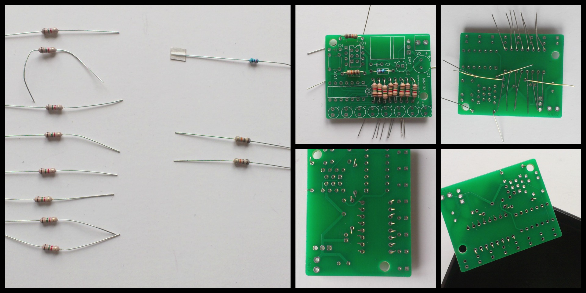
That's how they look. If you look closely, we will see that we have 8 identical, 2 more identical and 1 "in itself". Need to look closely to the striped markings on the body. On the board, the location for the resistor is denoted R (resistor). The first 8 identical ones stand in a row at the bottom, as is seen on the board, 2 more identical ones from the left above and one that “by itself” is actually mounted “by itself”.
At this stage, do not miss the opportunity to play with a multimeter. The brochure describes in detail how to measure the resistance of a resistor .
Good news: resistors do not have polarity. This means that it does not matter to us which side we will put them on the board. Therefore, without thinking for a long time, we give the necessary form to the contacts, we plant everyone on the board, we cut off the excess with a pliers. To make it convenient to solder, we put the board on the edge of a small cardboard box, since if we put it on the table, it would not allow us to solder the resistors a little above the board, as recommended.
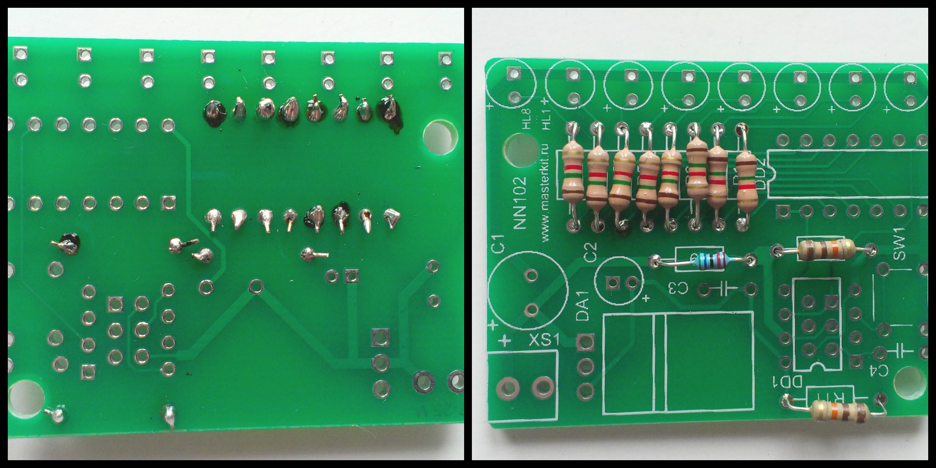
That's what we get. Still far from ideal, but much better than the first set! We continue.

Now select all capacitors. On the board, the places for them are indicated by C (capacitor). Capacitors are polar, and there are non-polar. This means that some capacitors, if they are not put on the board by the wrong side, will not work and the whole clutch will not work. Hint: yellow capacitors are non-polar, so just put them in the nests C3 and C4.
Cylindrical capacitors are polar. How to determine the polarity? Two ways:
1. Before trimming the legs, the one that is longer is a plus. It is enough to combine it with the marking “+” in the landing slot of a C1 or C2 capacitor.
2. The blue bar on the capacitor is the “key”. It is where the minus. It is enough to place it on the reverse side of the "plus" marking.
Hint: if you think lazy, just land the polar capacitors as in the image.
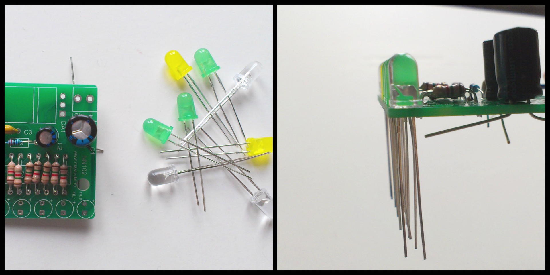
And diodes! The diodes are all polar. Ways to determine polarity:
1. Longer leg - plus.
2. Chamfer (bevel) on the side of the base of the diode itself. It is not convenient, since it is almost not visible from transparent diodes. All the chamfers of the diodes on this board should be on one side - external.
3. Put the multimeter in the ping mode (wi-fi icon, and in fact, a sound signal, on the multimeter), with a black wire (minus), touch the short leg, and the red (plus) one - long. In our case, the diode will light up. If you change the polarity - will not light up. This is because the diode passes current only in one direction.
If you confuse the polarity of at least one diode, then the whole chain will not burn. But! These three ways of determining the polarity of the diode did not let us down. The latter method can once again be used after mounting to ring the circuit and to make sure that the polarity of the diodes is not broken.
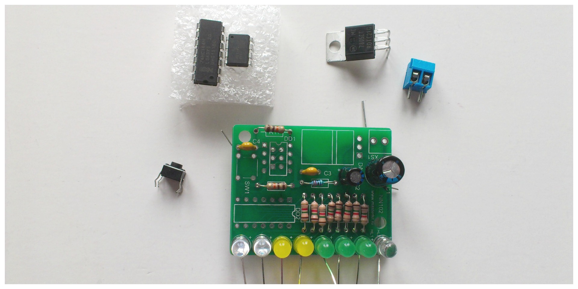
We only have a few more details. Clockwise on the photo:
Button. Not polar. Just put and press lightly - it will be fixed on the board.
Chips: they have "keys" on top of the case. For the one that is longer, this is a notch that must be combined with the designation on the board. In our case, the groove will look to the right, in the direction of the resistors. The smaller chip has a key in the form of a recess in the upper left corner. There he should be on the scheme. Also, this notch is schematically indicated on the board, also on top.
Pay attention to the good old "tube" (in the sense - cozy) DIP-chips . Now, apart from kits for creativity, there are few places where you can meet them, although for me personally it is a pleasure to solder them, as well as to assemble gear mechanisms. In industry, the traditional methods used by our parents and grandmothers and grandfathers of those to whom this set were intended to be replaced by surface mounting .
Chip voltage regulator . With it, everything is simple, nothing happens.
Terminal block Here we will connect the power supply. Therefore, it is important: at the terminal connector, the holes for the wire should look outside the board, otherwise they will close the capacitor close by itself, and it will be difficult to rivet the wires in the terminal (in fact, this is what happened with us). In case of improper placement of the terminal connector, it is most likely that it will not work out without a vacuum tin sucker (we did not succeed).
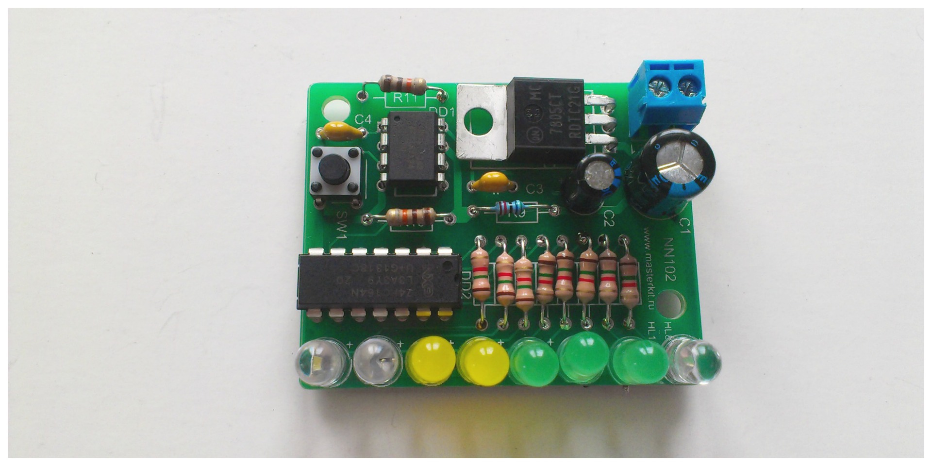
Done! We managed to make only one significant error during assembly - this is the location of the terminal connector. But this does not affect the polarity, but rather on the ease of use.
We got a mini-checking device that will always show how many more batteries are left. Now we will set it up to check the Krone battery, which we already have and in which the charge is 9V, until it has sat down.
Remember, we recommended you not to solder the wires with the terminals for the battery in the first circuit? If soldered - drop out, now we need them.
We connect a new, not yet dead battery. We observe the polarity (the positive terminal of the terminal is marked on the board). The first red LED lights up. The circuit works!
Briefly press the button. The device measures the voltage at 9V and remembers it. If we had near Krona sat down, we could check the difference in charge.
Hint: you can quickly discharge the Krona using the first scheme if you, of course, correctly assembled it. As we have said, it consumes up to 200 mA, so it will discharge the battery in about three hours.
Actually, the multimeter included in the kit handles the same functions of measuring voltage, but it does, of course, not so effectively. If you have a laboratory power supply, you can reprogram our device each time under a new voltage. The same can be done by connecting different batteries and pressing the "remember" button again.
Thanks to this two-day immersion in electronics, it became clear to me what else I want to know:
1. How to ring a mounted PCB to find where the defect is and repair it, rather than re-soldering the entire board (I still have hope to reassemble the first device!).
2. How to calculate the power consumption of the circuit and independently calculate how long this or that battery will last?
3. Three indicators that we measured during the assembly process using a multimeter - the number of volts in the battery, the resistance in Ohms resistor, the measurement of current in amperes. How are they interrelated and what can I do about it?
4. How to read the circuit diagram of the device and see it on the board? How to combine p. 3 and p. 4?
Therefore, I want to contact you, Habr. Please share the links to articles and books on this topic that you liked, which are easy to read, and can be quickly understood.
And also, tell me, please, what would you do with the power supply of devices, terminals and connectors, because so far I only have the option of "two sticking out wires and a Krone battery."
I hope this review will also help someone to “enter” the desired topic faster and easier. Good luck to you!
From the shelf of the children's store was taken another set, specifically this one .
')
So, we are testing the “Young Electronics Engineer Set”. Will it be possible with his help to assemble working structures from scratch without having preliminary skills, as we did with the mechanical model before?
The set already has everything to quickly complete the assembly:
- soldering iron, solder with a flux channel (very convenient!) and wire cutters
- multimeter
- two printed circuit boards with details
Those. there is something to solder, what to solder and, which is important - how to check the components and the already prepared circuit.
Also, the kit includes two brochures:
1. Methodical manual, which contains general information about the devices, parts and the process of soldering.
2. Instructions for collecting two members of a set of devices and the subsequent configuration of one of them.
The brochures are good, but if you remember, I liked the instructions for the robot, where there were no words - only the images + step by step the assembly was written. The instructions for this set of step-by-step instructions are not. In some ways, this is good, because if you are guided by these two brochures, you want to, you don't want, you have to read and understand everything first, and only then act - that is, they teach you to think systematically. But there is a little lack of dynamics, and, it seems to me, the children may also miss more than me. Therefore, if you collect something like that, I hope this post will save you a lot of time.
Additional tools
What is not in the set, but will be needed or may be needed:
1. Tweezers. We took a manicure.
2. Battery "Krona" on 9V
3. Phillips screwdriver - in one of the schemes there is a terminal. Tighten the wires in it will turn clockwise screwdriver.
4. A “third hand” soldering device - this is what you can do without, although it is constantly mentioned in the instructions and the brochure. Of course, it would be more convenient with her, but if you just collect all the parts on the board and then turn it over, then both the boards included in the kit will be relatively stable and will be soldered in principle conveniently and without additional devices.
5. Magnifier
6. Desoldering pump
7. Goggles and respirator
8. Soldering Iron Stand
9. Fan \ exhaust
Of the entire list, it will be very tight without the first two items. At this time, the robot from the previous post became a support for the soldering iron. The rest for mounting two small boards would really be superfluous.
But it would be useful to remind you that when soldering, tin pairs are released that are not very good for health. Actually the soldering of the two included circuits took me no more than 10 minutes and I did not poplohe. However, a small fan, driving away smoke to the side, or at least an open window is a standard and very good practice. In addition, after soldering, you need to wash your hands. You should also take care of your eyes - a leg of a part bit off with a nipper can fly off or a drop of hot tin can fly off during the soldering process (although we did not fly away). Therefore, wear safety glasses. Take care of yourself!
Nutrition
To begin with, all we need is a separately purchased “Krona” battery. The set has a connector for it, which, according to the instructions, must be soldered into the first circuit. My advice: do not do it, leave it like that and use it in both schemes - for testing the first one and for setting up the second one.
Devices that we collect, consume some kind of insane amount of mA \ hour.
If we are talking about an electrical circuit, then our resources and how we quickly spend them are measured in A \ h (Ampere per hour, mAh). Capacity typical "Krona" (according to the passport):
625 mA · h ≈ 0.5 A · h
The first device, the Chameleon, consumes up to 200 mAh. Therefore, our Krona this scheme is enough for:
625mAh / 200mA = 3.125 hours.
so it is recommended to use it only to check the operation of the circuit. A good output would be a 12 volt battery with a capacity of at least 0.5 Ah.
mAh - this is how quickly the battery will sit down! =)
It would be cool to be able to solder one of these connectors onto the boards, and then plug in such a laboratory power supply into it . But under one of the available connectors on the board there are no suitable holes. Therefore, we can not connect the power supply yet.
First damn lump or immediate troubleshooting
There is such an anecdote: a man bought a plane and a magazine with the description “How to make a dead loop”. Following the instructions, I got on the plane, took off, started to make a dead loop - everything works out. Turns the page, and there: "... exit from the dead loop, read the next issue."
You can talk a lot about the culture of soldering and that this is a whole art. One thing will remain the same: if you do something for the first time and on the book, then at first it may not work. Here is our first board, a set of "Chameleon", or rather what came of it. What mistakes were made?
1. Soldering technology is broken, as a result - non-soldered contacts, which are better to be soldered and soldered again (without mixing up the polarity!)
2. Violation of the work technology: each part was soldered in turn. Below you will see how much more profitable in this plan is to listen to the instructions and first collect all the details and then fix them.
Result: the parts stand beautifully in the curve and in the cavity, and of the three diode chains, only one of them caught fire.
Possible solution: drop all the parts and solder again.
Positive moment: you can always find. In this case, we do not have “parasitic jumpers” anywhere. True, it is enough to remove them simply in any case: just hold the tip of the soldering iron and separate the contacts that have been soldered together.
To solder!
So, the first scheme did not work out for us due to the violation of the soldering technology, therefore we will immediately discuss this simple and really pleasant moment.
The brochure clearly shows and tells how to solder, but, unfortunately, it did not help me much, because it says “how to”, but I would like to understand the technique itself.
Perhaps the best recommendation that was found was in this post . I will give it entirely:
It's all about the process. Do it like this:
- The part is inserted into the board and must be secured (you will not have a second hand to hold).
- In one hand, a soldering iron is taken, in the other - solder wire (conveniently, if it is in a special dispenser, as in the picture).
- Solder soldering iron is not necessary.
- Touch the soldering iron tip with the soldering point and warm it. Usually, it is 3-4 seconds. (actually 1-2 sec. - approx. A.Ch.)
- Then, without removing the soldering iron, with your second hand, touch the tip of the solder wire with the flux of the soldering point. In reality, in this place all three parts touch at once: the element of soldering and its hole on the board, the soldering iron and the solder. After a second, “pshshshshsh” occurs, the tip of the solder wire melts (and a little flux flows out of it) and the required amount of it passes to the soldering point. After a second, you can remove the soldering iron with solder and blow.
In addition, I can recommend an illustrated comic , translated by the atarity user .
Also, from time to time a deposit is formed on the soldering iron tip and needs to be cleaned. To do this, the industry uses special cellulose sponges, which are necessarily moistened with water. In our case, the carbon can be removed simply by shaking it off mechanically - for example, by the blunt side of the knife.
Step-by-step instruction
After the first device was unjustly ruined by us, an understanding of how to build the process more effectively appeared. I hope this step-by-step instruction will help you just as quickly assemble your own set.
So, we have a handful of details and we have no idea what's what. We take cute manicure tweezers (which was at home) and select all resistors from this pile.
That's how they look. If you look closely, we will see that we have 8 identical, 2 more identical and 1 "in itself". Need to look closely to the striped markings on the body. On the board, the location for the resistor is denoted R (resistor). The first 8 identical ones stand in a row at the bottom, as is seen on the board, 2 more identical ones from the left above and one that “by itself” is actually mounted “by itself”.
At this stage, do not miss the opportunity to play with a multimeter. The brochure describes in detail how to measure the resistance of a resistor .
Good news: resistors do not have polarity. This means that it does not matter to us which side we will put them on the board. Therefore, without thinking for a long time, we give the necessary form to the contacts, we plant everyone on the board, we cut off the excess with a pliers. To make it convenient to solder, we put the board on the edge of a small cardboard box, since if we put it on the table, it would not allow us to solder the resistors a little above the board, as recommended.
That's what we get. Still far from ideal, but much better than the first set! We continue.
Now select all capacitors. On the board, the places for them are indicated by C (capacitor). Capacitors are polar, and there are non-polar. This means that some capacitors, if they are not put on the board by the wrong side, will not work and the whole clutch will not work. Hint: yellow capacitors are non-polar, so just put them in the nests C3 and C4.
Cylindrical capacitors are polar. How to determine the polarity? Two ways:
1. Before trimming the legs, the one that is longer is a plus. It is enough to combine it with the marking “+” in the landing slot of a C1 or C2 capacitor.
2. The blue bar on the capacitor is the “key”. It is where the minus. It is enough to place it on the reverse side of the "plus" marking.
Hint: if you think lazy, just land the polar capacitors as in the image.
And diodes! The diodes are all polar. Ways to determine polarity:
1. Longer leg - plus.
2. Chamfer (bevel) on the side of the base of the diode itself. It is not convenient, since it is almost not visible from transparent diodes. All the chamfers of the diodes on this board should be on one side - external.
3. Put the multimeter in the ping mode (wi-fi icon, and in fact, a sound signal, on the multimeter), with a black wire (minus), touch the short leg, and the red (plus) one - long. In our case, the diode will light up. If you change the polarity - will not light up. This is because the diode passes current only in one direction.
If you confuse the polarity of at least one diode, then the whole chain will not burn. But! These three ways of determining the polarity of the diode did not let us down. The latter method can once again be used after mounting to ring the circuit and to make sure that the polarity of the diodes is not broken.
We only have a few more details. Clockwise on the photo:
Button. Not polar. Just put and press lightly - it will be fixed on the board.
Chips: they have "keys" on top of the case. For the one that is longer, this is a notch that must be combined with the designation on the board. In our case, the groove will look to the right, in the direction of the resistors. The smaller chip has a key in the form of a recess in the upper left corner. There he should be on the scheme. Also, this notch is schematically indicated on the board, also on top.
Pay attention to the good old "tube" (in the sense - cozy) DIP-chips . Now, apart from kits for creativity, there are few places where you can meet them, although for me personally it is a pleasure to solder them, as well as to assemble gear mechanisms. In industry, the traditional methods used by our parents and grandmothers and grandfathers of those to whom this set were intended to be replaced by surface mounting .
Chip voltage regulator . With it, everything is simple, nothing happens.
Terminal block Here we will connect the power supply. Therefore, it is important: at the terminal connector, the holes for the wire should look outside the board, otherwise they will close the capacitor close by itself, and it will be difficult to rivet the wires in the terminal (in fact, this is what happened with us). In case of improper placement of the terminal connector, it is most likely that it will not work out without a vacuum tin sucker (we did not succeed).
Done! We managed to make only one significant error during assembly - this is the location of the terminal connector. But this does not affect the polarity, but rather on the ease of use.
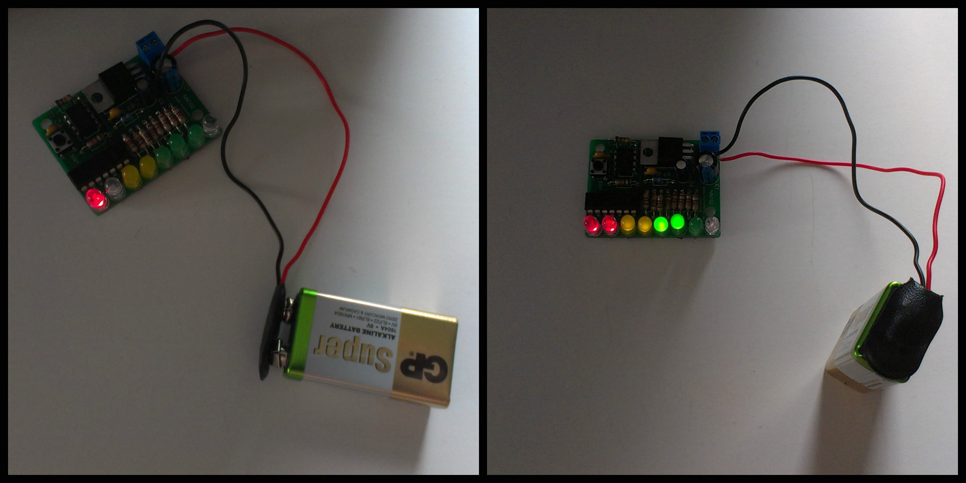
We got a mini-checking device that will always show how many more batteries are left. Now we will set it up to check the Krone battery, which we already have and in which the charge is 9V, until it has sat down.
Remember, we recommended you not to solder the wires with the terminals for the battery in the first circuit? If soldered - drop out, now we need them.
We connect a new, not yet dead battery. We observe the polarity (the positive terminal of the terminal is marked on the board). The first red LED lights up. The circuit works!
Briefly press the button. The device measures the voltage at 9V and remembers it. If we had near Krona sat down, we could check the difference in charge.
Hint: you can quickly discharge the Krona using the first scheme if you, of course, correctly assembled it. As we have said, it consumes up to 200 mA, so it will discharge the battery in about three hours.
Actually, the multimeter included in the kit handles the same functions of measuring voltage, but it does, of course, not so effectively. If you have a laboratory power supply, you can reprogram our device each time under a new voltage. The same can be done by connecting different batteries and pressing the "remember" button again.
In conclusion, I would like to say thanks to those who invented and created this set . Two days ago, I did not have the slightest idea about the process of installing printed circuit boards. Now I distinguish a resistor from a transistor and I can put them on the board using keys, a multimeter and other hints. In addition, one of the devices I was able to immediately assemble and launch into work! As always, it is very nice: to see and hold in your hands what you managed to assemble yourself.
Thanks to this two-day immersion in electronics, it became clear to me what else I want to know:
1. How to ring a mounted PCB to find where the defect is and repair it, rather than re-soldering the entire board (I still have hope to reassemble the first device!).
2. How to calculate the power consumption of the circuit and independently calculate how long this or that battery will last?
3. Three indicators that we measured during the assembly process using a multimeter - the number of volts in the battery, the resistance in Ohms resistor, the measurement of current in amperes. How are they interrelated and what can I do about it?
4. How to read the circuit diagram of the device and see it on the board? How to combine p. 3 and p. 4?
Therefore, I want to contact you, Habr. Please share the links to articles and books on this topic that you liked, which are easy to read, and can be quickly understood.
And also, tell me, please, what would you do with the power supply of devices, terminals and connectors, because so far I only have the option of "two sticking out wires and a Krone battery."
I hope this review will also help someone to “enter” the desired topic faster and easier. Good luck to you!
Source: https://habr.com/ru/post/256559/
All Articles