CAN-USB adapter from stm32vldiscovery
When developing devices with a CAN interface, it is desirable to have a handy tool for tracking messages on the network. For RS232 / 485 there are a lot of budget USB adapters and a lot of various software, but for CAN I did not manage to find an inexpensive ready-made solution.
At the same time on the sites of motorists there were home-made devices for connecting to the CAN bus of the car. One of the finished projects were USB <> CAN Bus Interface (CAN Hacker), implemented on the Atmega + SJA1000 and the project STM32-CAN-Busadapter, implemented on the STM32F105. They work with the program CAN Hacker, which looks comfortable enough to work. A cursory analysis of the protocol of commands via USB showed that these devices are represented by a COM port, and further communication takes place in the form of transmission of commands from ASCII characters.
')
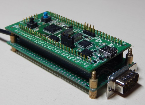
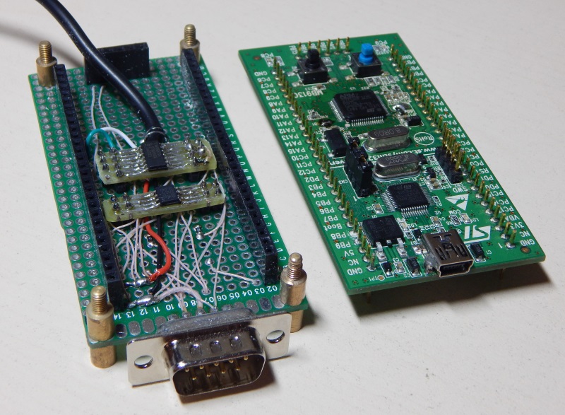
In the bins was found board STM32VLDiscovery, which became the object of the test. On it we will repeat the “STM32-CAN-Busadapter”.
The first step is to replace the STM32F100 microcontroller installed on STM32VLDiscovery. The fact is that simultaneous operation of CAN and USB in the F1 series is possible only in STM32F105 / 107 microcontrollers. It is good that the STM has pin-to-pin compatibility of microcontrollers of various series, but made in the same package.
The local store purchased:
1. STM32F105RBT6 297 rubles.
2. PCA82C250T 115 rub.
3. TJA1055T 138 rubles.
4. PBS-40, 2pcs. 114 rub.
The development board “with holes 2.54” has been waiting for its time for a long time.
Attempt to do everything quickly
We erase dust from STM32VLDiscovery, check that it still works by downloading the Demo project. We rewire the controller, check that the transfer was successful by downloading the same project.
From the site of the project STM32-CAN-Busadapter we download (registration is required) the binary firmware file and sew it into our controller using the “STM32 ST-LINK Utility”.
A simplified diagram looks like this. More detailed - on the site of the project STM32-CAN-Busadapter.
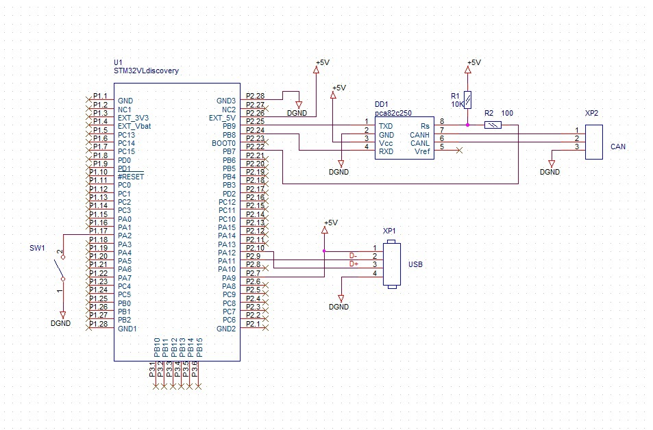
We solder USB D +, D-, Vbus in accordance with the scheme. Add a jumper / switch on PA2, the author has a name “Bootloader”.
Turn on and ...., nothing works , the device via USB is not detected at all. In all positions "Bootloader".
We recall that in order to determine the USB connection, it is necessary to pull the D + line to 5V through a 1.5KΩ resistor. After that, our device begins to be defined as an “unknown device” with vid / pid 0000.
Then there were several hours of trying to figure out what was happening, and it was decided to write a test firmware to check the USB connection.
We write a test firmware to check the USB
To write a test firmware, we use STM32CubeMX, which will allow us to quickly concoct a test firmware. According to ST and distributors, the use of CubeMX is “fashionable, stylish, youthful”, you must try to deal with this Cub.
From STMicroelectronic we download STM32CubeMX. The version is updated periodically, I have v4.7.0.
In the installed Cube, we enter “Help” -> “Install New Libraries” and install “Firmware Package for Family STM32F1” (I have V1.0.0).
In “Help” -> “Updater Settings” you can see “Repository Folder” - the place where our “Firmware Package” has downloaded, there are also examples with source codes for various debugging boards.
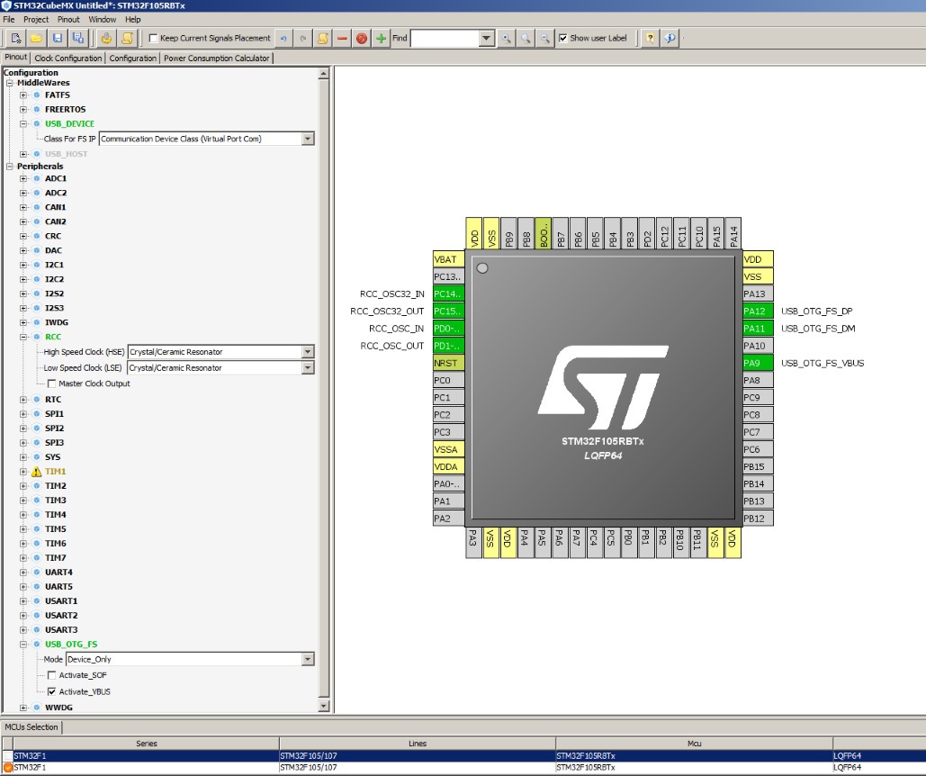
Create a new project in Cube
MCU - STM32F105RBTx.
In “Configuration” -> “Peripheals” -> “RCC” we select clocking from external quartz resonator, HSE is set in “Crystal / Ceramic Resonator”.
In “Configuration” -> “Peripheals” -> “USB_OTG_FS”, select the “Device_Only” mode, and set the “Activate_VBUS” checkbox to automatically determine when to connect to USB. After that, we automatically assign PA9, PA11 and PA12 legs to work with USB.
In “Configuration” -> “MiddleWares” -> “USB_DEVICE” -> “Class For FS IP” select “Communication Device Class (Virtual Port Com)”.
Next on the tab "Clock Configuration" configure the clock system for our microcontroller. You can see the finished values of the PLL and Prescaler coefficients in the examples by looking at the SystemClock_Config procedure. We should have this “picture”:
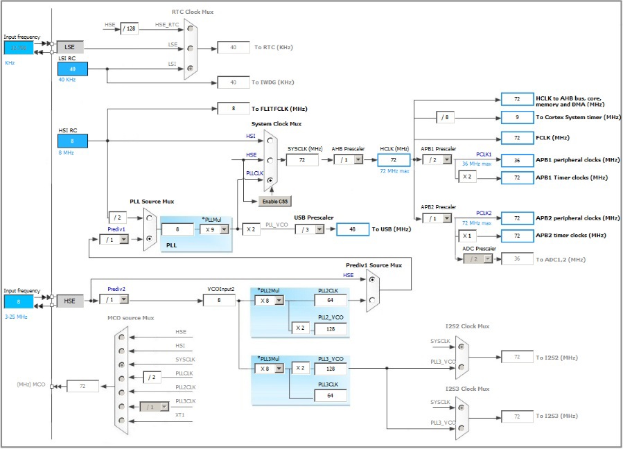
Now you can generate a project to compile.
Before the first generation, it will ask you to enter the name, storage location of the project and the IDE for which the project will be formed. I chose Keil 4 as more familiar. The options are Keil5, Keil4, IAR, TrueStudio, SW4STM32. After generation, click "Open Project" and our development environment opens. Without changing anything we compile and load.
And ... it works . The device was determined, the drivers were found on the ST site. Now in the "Device Manager" see "STMicroelectronics Virtual COM Port (COM4)".
Further, it took some time to understand why the iron works, but there is no foreign firmware. As a result, it was noticed that binary files look different.
I remember that at the beginning of the program there are interrupt vectors and in our firmware we see something similar, and in the downloaded firmware the data is not at all similar to the commands to go to addresses.

Moreover, Google suggested that the first 4 bytes of the firmware are the stack address, the next 4 bytes are the address of the first program command.
I wrote to the author STM32-CAN-Busadapter. Described that the firmware is "broken", does not work, that the first bytes are not the same as they should be. Andreas answered me. I wrote that the firmware is working, but it requires its proprietary loader. Attached to the letter was a .hex file “personally version only for you”.
OK, look how it works
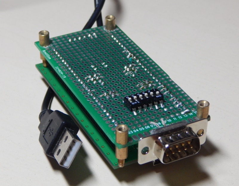
We solder the CAN transceiver chips, we get just such a “beauty”. Pull-up resistor to D + USB line can be removed, it is inside the microcontroller.
We are stitching, launching CAN Hacker, studying. Here we need to connect to some CAN network. I had this openmcu board with an STM32F107 controller, which issued CAN packages. Having played with the “CAN Hacker” program, I realized that the piece was suitable, there are monitor and tracer modes - the messages are displayed either in the table or in the list as they are received.
Here is a short video, not mine.
Now you can try to write your own firmware for the adapter. Moreover, we already have a firmware package.
We are writing our firmware ...
Open in our IDE project, generated by Cube and append the missing pieces of code.
The basic rule is to write between
/ * USER CODE BEGIN ... * /
and
/ * USER CODE END ... * /
Otherwise, everything that is written outside of such specially designated places will be mercilessly overwritten by Cub in the next generation of the project.
To begin, let's make an echo : everything that was sent to our virtual COM port we get back.
When receiving data via USB, the CDC_Receive_FS procedure (uint8_t * Buf, uint32_t * Len) is called in the file " usbd_cdc_if.c ".
Let's add sending back all that received.
Echo
static int8_t CDC_Receive_FS (uint8_t * Buf, uint32_t * Len)
{
/ * USER CODE BEGIN 6 * /
CDC_Transmit_FS (Buf, * Len); // send everything we received
USBD_CDC_SetRxBuffer (hUsbDevice_0, & UserRxBufferFS [0]);
USBD_CDC_ReceivePacket (hUsbDevice_0); // allow reception of the next packet
return (USBD_OK);
/ * USER CODE END 6 * /
}
{
/ * USER CODE BEGIN 6 * /
CDC_Transmit_FS (Buf, * Len); // send everything we received
USBD_CDC_SetRxBuffer (hUsbDevice_0, & UserRxBufferFS [0]);
USBD_CDC_ReceivePacket (hUsbDevice_0); // allow reception of the next packet
return (USBD_OK);
/ * USER CODE END 6 * /
}
Compile, load. We open our virtual COM port with any terminal program. Port parameters (speed, parity) can be any. Make sure that the echo works.
Adjusting to CAN Hacker
Now we will start the implementation of the protocol for working with the program “CAN Hacker”. The protocol itself can be viewed on the USB <> CAN Bus Interface (CAN Hacker) project page, in the “description” file, or searched on the Internet by the name of “Lawicel Protokol”.
The USBTrace program oversaw the adapter initialization process.
You must answer the command "version request", for all other requests simply answer "OK" (0x0D).
Change the procedure CDC_Receive_FS
static int8_t CDC_Receive_FS (uint8_t * Buf, uint32_t * Len)
{
/ * USER CODE BEGIN 6 * /
uint32_t num_bytes;
uint8_t res;
uint8_t tmp_byte;
HAL_GPIO_TogglePin (GPIOC, GPIO_PIN_9);
switch (Buf [0])
{
case 'v':
num_bytes = sprintf ((char *) UserTxBufferFS, "V0101 \ r");
break;
case 'v':
num_bytes = sprintf ((char *) UserTxBufferFS, "vSTM32 \ r");
break;
default:
num_bytes = sprintf ((char *) UserTxBufferFS, "\ r");
break;
}
USBD_CDC_SetTxBuffer (hUsbDevice_0, (uint8_t *) & UserTxBufferFS [0], num_bytes);
USBD_CDC_TransmitPacket (hUsbDevice_0);
// CDC_Transmit_FS (Buf, * Len);
USBD_CDC_SetRxBuffer (hUsbDevice_0, & UserRxBufferFS [0]);
USBD_CDC_ReceivePacket (hUsbDevice_0);
return (USBD_OK);
/ * USER CODE END 6 * /
}
{
/ * USER CODE BEGIN 6 * /
uint32_t num_bytes;
uint8_t res;
uint8_t tmp_byte;
HAL_GPIO_TogglePin (GPIOC, GPIO_PIN_9);
switch (Buf [0])
{
case 'v':
num_bytes = sprintf ((char *) UserTxBufferFS, "V0101 \ r");
break;
case 'v':
num_bytes = sprintf ((char *) UserTxBufferFS, "vSTM32 \ r");
break;
default:
num_bytes = sprintf ((char *) UserTxBufferFS, "\ r");
break;
}
USBD_CDC_SetTxBuffer (hUsbDevice_0, (uint8_t *) & UserTxBufferFS [0], num_bytes);
USBD_CDC_TransmitPacket (hUsbDevice_0);
// CDC_Transmit_FS (Buf, * Len);
USBD_CDC_SetRxBuffer (hUsbDevice_0, & UserRxBufferFS [0]);
USBD_CDC_ReceivePacket (hUsbDevice_0);
return (USBD_OK);
/ * USER CODE END 6 * /
}
After this, the program “CAN Hacker” will be able to “see” our adapter.
Add CAN interface to our project.
In Cube, set the “Configuration” -> “Peripheals” -> “CAN1” tick “Master mode”. On the “Configuration” tab “CAN1” we set the speed and enable the interrupt by reception:
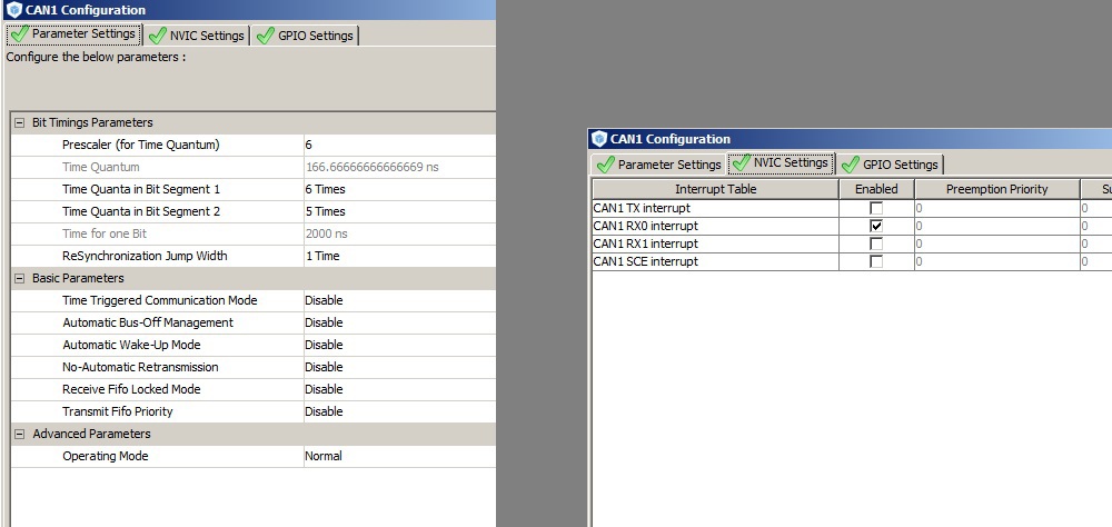
The exchange rate for CAN is obtained configured at 500 Kbps.
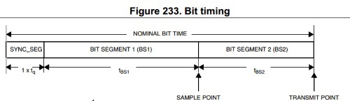
The clocking frequency of the CAN module from the APB1 bus is 36 MHz, we divide it by 6, we get the time of one quantum.
One byte is transmitted 1 + 6 + 5 quanta, and it turns out 36/6 / (1 + 6 + 5) = 0.5 MHz, or 500 Kbps.
By changing the “Prescaler (for Time Quantum)” divider, we can get standard speeds of 125,250,500,1000 Kbps.
One byte is transmitted 1 + 6 + 5 quanta, and it turns out 36/6 / (1 + 6 + 5) = 0.5 MHz, or 500 Kbps.
By changing the “Prescaler (for Time Quantum)” divider, we can get standard speeds of 125,250,500,1000 Kbps.
We generate the project in Cube, we open in IDE.
In “main.c”, you need to add buffers for CAN, configure an incoming message filter and add the procedure HAL_CAN_RxCpltCallback . This procedure will be called from the CAN interrupt. The name, of course, can only be so, because it is written in the “depths” of the project generated by Cub. All that was received by CAN will be sent to USB, in accordance with the protocol. For example, by CAN, from the address 0x123, we received 8 bytes of data 0x11 0x22 0x33 0x44 0x55 0x66 0x77 0x88, we pack this into the “t12381122334455667788” USB package and add the 0x0D symbol to the end and send it to our virtual COM port on the PC.
Add CAN reception parcels
receive / transmit buffers
/ * USER CODE BEGIN PV * /
static CanTxMsgTypeDef can1TxMessage;
static CanRxMsgTypeDef can1RxMessage;
/ * USER CODE END PV * /
procedure called upon receiving the parcel
/ * USER CODE BEGIN 0 * /
void HAL_CAN_RxCpltCallback (CAN_HandleTypeDef * CanHandle)
{
uint32_t num_bytes;
uint8_t buf [200];
num_bytes = sprintf ((char *) buf, "t% 3.3X% 1.1X% 2.2x% 2.2x% 2.2x% 2.2x% 2.2x% 2.2x% 2.2x% 2.2x% 4.4x \ r", \
CanHandle-> pRxMsg-> StdId, \
CanHandle-> pRxMsg-> DLC, \
CanHandle-> pRxMsg-> Data [0], \
CanHandle-> pRxMsg-> Data [1], \
CanHandle-> pRxMsg-> Data [2], \
CanHandle-> pRxMsg-> Data [3], \
CanHandle-> pRxMsg-> Data [4], \
CanHandle-> pRxMsg-> Data [5], \
CanHandle-> pRxMsg-> Data [6], \
CanHandle-> pRxMsg-> Data [7] \
);
CDC_Transmit_FS (buf, num_bytes); // send to USB what we received via CAN
HAL_CAN_Receive_IT (& hcan1, CAN_FIFO0); // waiting for the next package
}
/ * USER CODE END 0 * /
To use the external function CDC_Transmit_FS, we include the .h file
/ * USER CODE BEGIN Includes * /
#include "usbd_cdc_if.h"
/ * USER CODE END Includes * /
in the main main loop, add initialization of buffers and configure the receive filter
/ * USER CODE BEGIN 2 * /
hcan1.pTxMsg = & can1TxMessage;
hcan1.pRxMsg = & can1RxMessage;
/ * USER CODE END 2 * /
// set up the filter - receive all parcels
CAN_FilterConfTypeDef canFilterConfig;
canFilterConfig.FilterNumber = 0;
canFilterConfig.FilterMode = CAN_FILTERMODE_IDMASK;
canFilterConfig.FilterScale = CAN_FILTERSCALE_32BIT;
canFilterConfig.FilterIdHigh = 0x0000;
canFilterConfig.FilterIdLow = 0x0000;
canFilterConfig.FilterMaskIdHigh = 0x0000 << 5;
canFilterConfig.FilterMaskIdLow = 0x0000;
canFilterConfig.FilterFIFOAssignment = 0;
canFilterConfig.FilterActivation = ENABLE;
canFilterConfig. BankNumber = 1;
HAL_CAN_ConfigFilter (& hcan1, & canFilterConfig);
HAL_CAN_Receive_IT (& hcan1, CAN_FIFO0); // allow receiving parcels
/ * USER CODE END 2 * /
resize USB buffers additionally
#define APP_RX_DATA_SIZE 1000 // was 4
#define APP_TX_DATA_SIZE 1000 // was 4
It is also important not to forget that the CAN transceiver has an input for switching to Standby mode.
In Cube, assign PB7 to exit. The default output will be 0.
We compile, load, check. In principle, it works. In CAN Hacker we can see from CAN, but if the time between CAN packets is less than 1 ms, then messages are skipped, they come through one.
Picture for example. Every millisecond two parcels arrive, in CAN Hacker we see only one.
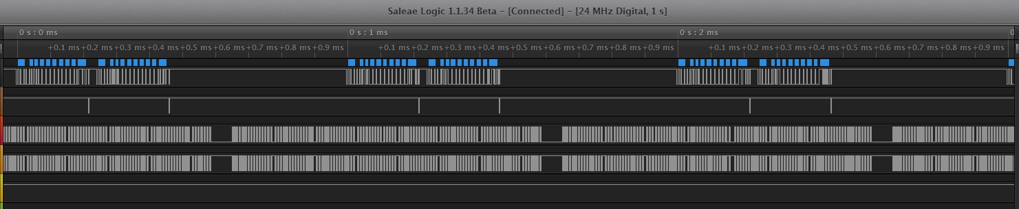
channel 1 - CAN RX, accept to controller
channel 2 - CAN TX, you can see confirmation from our controller
channel 3.4 -USB D +, D-
In addition, if there is an intensive exchange on the CAN bus, then our adapter is not detected via USB, an “unknown device” writes.
You have to first connect the USB, run CAN Hacker, then connect the CAN.
Add a ring buffer to receive CAN parcels
Obviously, while we are building and sending a parcel from CAN to USB, at this time the next parcel has time to slip into CAN, and it remains unprocessed. Therefore, when receiving a CAN parcel, we will quickly add everything to the buffer, and somewhere else in the other place we will scoop this buffer and send it to USB.
We will write to the buffer byte-by-byte, so it is easy to follow the “looping” - the transition from the end of the array in memory to the beginning.
Send from the buffer will be the USBD_CDC_SetTxBuffer and USBD_CDC_TransmitPacket procedures, indicating the beginning of the data to be sent and their number. If during sending you need to “make a ring”, then we send it in two stages, first the data until the end of the array in memory, then the remainder.

Ring Buffer Implementation
the buffer for sending USB is already defined
uint8_t UserTxBufferFS [APP_TX_DATA_SIZE];
in "usb_cdc_if.c" we define pointers to this buffer
uint32_t ptrWriteUserTxBufferFS = 0; // write to buffer when receiving from CAN
uint32_t ptrReadUserTxBufferFS = 0; // read from buffer, send to USB
/ * USER CODE END 1 * /
we describe the procedures for adding data to the buffer and sending from the buffer
Unfortunately, there was no normal place in “usb_cdc_if.c”, so I had to shove it into the “USBD_CDC_Private_Macros” section
/ * USER CODE BEGIN 2 * /
extern uint8_t UserRxBufferFS [APP_RX_DATA_SIZE];
extern uint8_t UserTxBufferFS [APP_TX_DATA_SIZE];
extern uint8_t interface_state;
extern USBD_HandleTypeDef * hUsbDevice_0;
// ------------------------------------------------ -------------------------------------------------- -------------------------------------------------- -------------
uint8_t CDC_add_buf_to_transmit (uint8_t * Buf, uint16_t Len) // add to transfer buffer
{
uint16_t _cnt = Len;
while (_cnt)
{
UserTxBufferFS [ptrWriteUserTxBufferFS] = * Buf;
ptrWriteUserTxBufferFS ++;
Buf ++;
ptrWriteUserTxBufferFS% = APP_TX_DATA_SIZE; // loopback
_cnt--;
}
return (0);
}
// ------------------------------------------------ -------------------------------------------------- -------------------------------------------------- -------------
uint8_t CDC_periodic_callback (void) // periodically check if there is data to transmit
{
uint32_t buffptr;
uint32_t buffsize;
if (ptrReadUserTxBufferFS! = ptrWriteUserTxBufferFS)
{
__disable_irq (); // with intensive exchange via CAN without this, everything “falls apart”
if (ptrReadUserTxBufferFS> ptrWriteUserTxBufferFS) // make a ring?
{
buffsize = APP_TX_DATA_SIZE - ptrReadUserTxBufferFS; // stage 1, byte to the end of the array
}
else
{
buffsize = ptrWriteUserTxBufferFS - ptrReadUserTxBufferFS; // all data at once
}
__enable_irq ();
buffptr = ptrReadUserTxBufferFS;
if (interface_state! = 1) return (1); // if the interface is not configured, we will not send
USBD_CDC_SetTxBuffer (hUsbDevice_0, (uint8_t *) & UserTxBufferFS [buffptr], buffsize);
if (USBD_CDC_TransmitPacket (hUsbDevice_0) == USBD_OK)
{
ptrReadUserTxBufferFS + = buffsize;
if (ptrReadUserTxBufferFS == APP_TX_DATA_SIZE)
{
ptrReadUserTxBufferFS = 0; // loopback
}
}
}
return (0);
}
/ * USER CODE END 2 * /
in the "main.c" add variable
uint8_t interface_state = 0;
until the command “O” comes from CAN Hacker - the transition to the operating mode from the setup mode, we will not send anything to USB, since we consider that the interface is not yet configured
replace in CAN interrupt direct send to USB to add to send buffer
CDC_Transmit_FS on CDC_add_buf_to_transmit
and add periodic polling buffer to send
while (1)
{
/ * USER CODE END WHILE * /
/ * USER CODE BEGIN 3 * /
CDC_periodic_callback ();
}
/ * USER CODE END 3 * /
Compile, load. We see that now in CAN Hacker all messages are displayed, without gaps.
Add Timestamp
The CAN Hacker protocol provides “time stamps” for each message. The range of values is 0..60000 ms.
Use for this TIM1.
In Cub, in “Configuration” -> “Peripheals” -> “TIM1” select “Clock source” = “Internal Clock”.
For setting the clocking frequency of the timer 1000 Hz (1ms). We'll have to lower the clocking frequency of the APB2.
We are convinced that nothing important in speed is clocked by APB2.
From the “reference manual” on “STM32F1”:
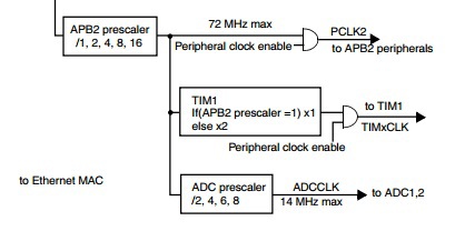
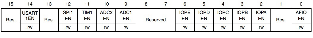
We see that timer1, I / O ports, ADC, SPI, USART are clocked from APB2, and we can safely lower the frequency of APB2.
In Cub, on the tab “Clock Configuration” set “APB2 Prescaler” equal to 8, we get the clock frequency of the timer 18 MHz.
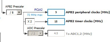
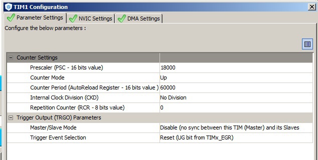
On the tab "Configuration" -> "TIM1" set
Prescaler (PSC - 16 bit value) = 18000
Counter period (AutoReload Register) = 60000
We generate the code, open it in the IDE.
We add in start of the timer
/ * USER CODE BEGIN 2 * /
HAL_TIM_Base_Start (& htim1);
HAL_TIM_Base_Start (& htim1);
add timestamp to CAN message to USB
void HAL_CAN_RxCpltCallback (CAN_HandleTypeDef * CanHandle)
{
uint32_t num_bytes;
uint8_t buf [200];
static uint32_t time;
time = __HAL_TIM_GetCounter (& htim1);
num_bytes = sprintf ((char *) buf, "t% 3.3X% 1.1X% 2.2x% 2.2x% 2.2x% 2.2x% 2.2x% 2.2x% 2.2x% 2.2x% 4.4x \ r", \
CanHandle-> pRxMsg-> StdId, \
CanHandle-> pRxMsg-> DLC, \
CanHandle-> pRxMsg-> Data [0], \
CanHandle-> pRxMsg-> Data [1], \
CanHandle-> pRxMsg-> Data [2], \
CanHandle-> pRxMsg-> Data [3], \
CanHandle-> pRxMsg-> Data [4], \
CanHandle-> pRxMsg-> Data [5], \
CanHandle-> pRxMsg-> Data [6], \
CanHandle-> pRxMsg-> Data [7], \
time
);
if (interface_state == 1) CDC_add_buf_to_transmit (buf, num_bytes);
HAL_CAN_Receive_IT (& hcan1, CAN_FIFO0);
}
Again, it seems to work, but with an intensive exchange in CAN, the USB exchange “shuts up”.
This time the sprintf procedure is to blame, which takes a long time to complete the interrupt CAN
Let's rewrite the formation of a parcel from CAN to USB without using sprintf.
Procedures for converting four bits to HEX ASCII character and vice versa
uint8_t halfbyte_to_hexascii (uint8_t _halfbyte)
{
_halfbyte & = 0x0F;
if (_halfbyte> = 10) return ('A' + _halfbyte - 10);
else return ('0' + _halfbyte);
}
uint8_t hexascii_to_halfbyte (uint8_t _ascii)
{
if ((_ ascii> = '0') && (_ascii <= '9')) return (_ascii - '0');
if ((_ ascii> = 'a') && (_ascii <= 'f')) return (_ascii - 'a');
if ((_ ascii> = 'A') && (_ascii <= 'F')) return (_ascii - 'A');
return (0xFF);
}
{
_halfbyte & = 0x0F;
if (_halfbyte> = 10) return ('A' + _halfbyte - 10);
else return ('0' + _halfbyte);
}
uint8_t hexascii_to_halfbyte (uint8_t _ascii)
{
if ((_ ascii> = '0') && (_ascii <= '9')) return (_ascii - '0');
if ((_ ascii> = 'a') && (_ascii <= 'f')) return (_ascii - 'a');
if ((_ ascii> = 'A') && (_ascii <= 'F')) return (_ascii - 'A');
return (0xFF);
}
change the procedure HAL_CAN_RxCpltCallback
void HAL_CAN_RxCpltCallback (CAN_HandleTypeDef * CanHandle)
{
uint32_t num_bytes;
uint8_t buf [200];
static uint32_t time;
time = __HAL_TIM_GetCounter (& htim1);
/ *
num_bytes = sprintf ((char *) buf, "t% 3.3X% 1.1X% 2.2x% 2.2x% 2.2x% 2.2x% 2.2x% 2.2x% 2.2x% 2.2x% 4.4x \ r", \
CanHandle-> pRxMsg-> StdId, \
CanHandle-> pRxMsg-> DLC, \
CanHandle-> pRxMsg-> Data [0], \
CanHandle-> pRxMsg-> Data [1], \
CanHandle-> pRxMsg-> Data [2], \
CanHandle-> pRxMsg-> Data [3], \
CanHandle-> pRxMsg-> Data [4], \
CanHandle-> pRxMsg-> Data [5], \
CanHandle-> pRxMsg-> Data [6], \
CanHandle-> pRxMsg-> Data [7], \
time
);
* /
num_bytes = 0;
buf [num_bytes ++] = 't';
buf [num_bytes ++] = halfbyte_to_hexascii ((CanHandle-> pRxMsg-> StdId) >> 8);
buf [num_bytes ++] = halfbyte_to_hexascii ((CanHandle-> pRxMsg-> StdId) >> 4);
buf [num_bytes ++] = halfbyte_to_hexascii ((CanHandle-> pRxMsg-> StdId));
buf [num_bytes ++] = halfbyte_to_hexascii ((CanHandle-> pRxMsg-> DLC));
buf [num_bytes ++] = halfbyte_to_hexascii ((CanHandle-> pRxMsg-> Data [0]) >> 4);
buf [num_bytes ++] = halfbyte_to_hexascii ((CanHandle-> pRxMsg-> Data [0]));
buf [num_bytes ++] = halfbyte_to_hexascii ((CanHandle-> pRxMsg-> Data [1]) >> 4);
buf [num_bytes ++] = halfbyte_to_hexascii ((CanHandle-> pRxMsg-> Data [1]));
buf [num_bytes ++] = halfbyte_to_hexascii ((CanHandle-> pRxMsg-> Data [2]) >> 4);
buf [num_bytes ++] = halfbyte_to_hexascii ((CanHandle-> pRxMsg-> Data [2]));
buf [num_bytes ++] = halfbyte_to_hexascii ((CanHandle-> pRxMsg-> Data [3]) >> 4);
buf [num_bytes ++] = halfbyte_to_hexascii ((CanHandle-> pRxMsg-> Data [3]));
buf [num_bytes ++] = halfbyte_to_hexascii ((CanHandle-> pRxMsg-> Data [4]) >> 4);
buf [num_bytes ++] = halfbyte_to_hexascii ((CanHandle-> pRxMsg-> Data [4]));
buf [num_bytes ++] = halfbyte_to_hexascii ((CanHandle-> pRxMsg-> Data [5]) >> 4);
buf [num_bytes ++] = halfbyte_to_hexascii ((CanHandle-> pRxMsg-> Data [5]));
buf [num_bytes ++] = halfbyte_to_hexascii ((CanHandle-> pRxMsg-> Data [6]) >> 4);
buf [num_bytes ++] = halfbyte_to_hexascii ((CanHandle-> pRxMsg-> Data [6]));
buf [num_bytes ++] = halfbyte_to_hexascii ((CanHandle-> pRxMsg-> Data [7]) >> 4);
buf [num_bytes ++] = halfbyte_to_hexascii ((CanHandle-> pRxMsg-> Data [7]));
buf [num_bytes ++] = halfbyte_to_hexascii ((time) >> 12);
buf [num_bytes ++] = halfbyte_to_hexascii ((time) >> 8);
buf [num_bytes ++] = halfbyte_to_hexascii ((time) >> 4);
buf [num_bytes ++] = halfbyte_to_hexascii ((time) >> 0);
buf [num_bytes ++] = '\ r';
if (interface_state == 1) CDC_add_buf_to_transmit (buf, num_bytes);
HAL_CAN_Receive_IT (& hcan1, CAN_FIFO0);
}
Some experiments on the speed of reception: in the CAN we form 1000000 parcels from the address 0x321 and in CAN Hacker we see how many of them we accept.
Speed 500 Kbps, sending without interruption, loss of 0.2%:
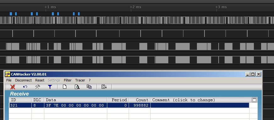
Speed 1 Mbit / s, sending without interruption, loss of 50%:

The speed is 1 Mbit / s, two parcels every 1 ms, the loss is 0%:
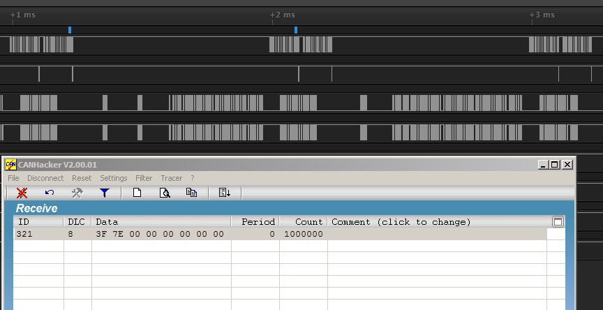
In my opinion a good result.
Add the ability to send messages to CAN
In the file “usbd_cdc_if.c”, in the USB procedure CDC_Receive_FS we add:
send to CAN
We compile, load, check, work.case 't':
i = 1;
hcan1.pTxMsg-> StdId = hexascii_to_halfbyte (Buf [i ++]);
hcan1.pTxMsg-> StdId = (hcan1.pTxMsg-> StdId << 4) + hexascii_to_halfbyte (Buf [i ++]);
hcan1.pTxMsg-> StdId = (hcan1.pTxMsg-> StdId << 4) + hexascii_to_halfbyte (Buf [i ++]);
hcan1.pTxMsg-> DLC = hexascii_to_halfbyte (Buf [i ++]);
tmp_byte = hexascii_to_halfbyte (Buf [i ++]); tmp_byte = (tmp_byte << 4) + hexascii_to_halfbyte (Buf [i ++]);
hcan1.pTxMsg-> Data [0] = tmp_byte;
tmp_byte = hexascii_to_halfbyte (Buf [i ++]); tmp_byte = (tmp_byte << 4) + hexascii_to_halfbyte (Buf [i ++]);
hcan1.pTxMsg-> Data [1] = tmp_byte;
tmp_byte = hexascii_to_halfbyte (Buf [i ++]); tmp_byte = (tmp_byte << 4) + hexascii_to_halfbyte (Buf [i ++]);
hcan1.pTxMsg-> Data [2] = tmp_byte;
tmp_byte = hexascii_to_halfbyte (Buf [i ++]); tmp_byte = (tmp_byte << 4) + hexascii_to_halfbyte (Buf [i ++]);
hcan1.pTxMsg-> Data [3] = tmp_byte;
tmp_byte = hexascii_to_halfbyte (Buf [i ++]); tmp_byte = (tmp_byte << 4) + hexascii_to_halfbyte (Buf [i ++]);
hcan1.pTxMsg-> Data [4] = tmp_byte;
tmp_byte = hexascii_to_halfbyte (Buf [i ++]); tmp_byte = (tmp_byte << 4) + hexascii_to_halfbyte (Buf [i ++]);
hcan1.pTxMsg-> Data [5] = tmp_byte;
tmp_byte = hexascii_to_halfbyte (Buf [i ++]); tmp_byte = (tmp_byte << 4) + hexascii_to_halfbyte (Buf [i ++]);
hcan1.pTxMsg-> Data [6] = tmp_byte;
tmp_byte = hexascii_to_halfbyte (Buf [i ++]); tmp_byte = (tmp_byte << 4) + hexascii_to_halfbyte (Buf [i ++]);
hcan1.pTxMsg-> Data [7] = tmp_byte;
HAL_CAN_Transmit (& hcan1, 10);
num_bytes = sprintf ((char *) UserTxBufferFS, "\ r");
break;
Conclusion
On this, perhaps, you can stop. The rubric for “do it yourself” is called. If anyone wants, he can independently add support for different CAN speeds, work with 29 bit extended identifiers, message filters, remote frames.
I want to say that I liked the principle of working through the ASCII command. In the future I plan to implement USB-SPI, USB-I2C functionality. For example, we configure our virtual COM port to 115200 baud - we work with CAN, we tune to 57600 - we work with I2C, we tune to 9600 - we work with SPI. Of course, when working with SPI or I2C, “CAN Hacker” can no longer be used and you have to invent some kind of protocol.
The finished draft for this article can be downloaded here .
Used materials
1. USB <> CAN Bus Interface (CAN Hacker)
2. STM32-CAN-Busadapter
3. Description and scheme of STM32VLDISCOVERY
4. STM32F105 Reference Manual
Source: https://habr.com/ru/post/256493/
All Articles