Blending Modes in Unity
Many have probably heard about the blend modes , which are present in most popular programs for working with images and video. There it is - an important tool for creating content, has long become an integral part of them.
And what about the games?
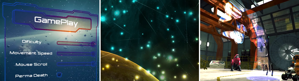
Let's say it became necessary to use Color Dodge mixing for a particle system, or the UI artist made beautiful graphics for the game interface, but some of its elements use some kind of Soft Light. Or maybe you needed to subject a three-dimensional object to a Divide-blending to get the effect straight from Lynch films?
')
In this article we will look at the principle of operation of the popular blending modes and try to recreate their effect as accurately as possible on the Unity game engine.
First, let's figure out what we need to do. Take for example two graphic elements and arrange them so that one overlaps the other:
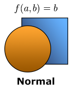
In the normal (Normal) blending mode, the color of each pixel of the lower layer ( a ) is completely replaced by the pixel color of the layer that “overlaps” it ( b ). Here everything is trivial: most of the graphic objects in games are “mixed” in this way.
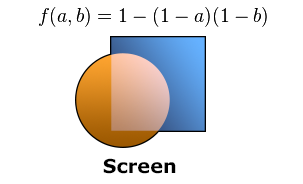
In Screen mode, the pixel colors of both layers are inverted, multiplied, and then inverted again. We implement this algorithm in Cg language :
Note that in the alpha component of the resulting color ( ra ), we transfer the alpha value of the upper layer ( ba ) in order to preserve the ability to independently control the level of transparency of the material.
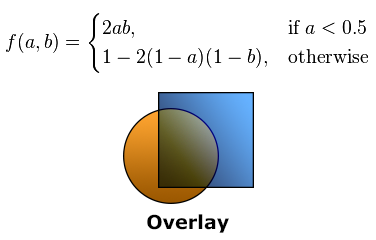
Overlay algorithm works conditionally: for the "dark" areas the colors are multiplied, and for the "light" ones the analogue of the Screen mode is used.

Blending mode Darken compares the values of each of the three color channels for the two layers and leaves the one that is “darker”.
Most of the other modes operate according to similar schemes. If you're interested, the implementation of another 18 mixing algorithms for Cg can be found here: gist.github.com/Elringus/d21c8b0f87616ede9014
So, our task in general form can be formulated as follows: for each pixel of the object's material ( b ), find the pixel that is “under it” ( a ) and, using the selected algorithm, “mix” them.
Having received all the necessary mixing algorithms, it may seem that things are small: you only need to get a - the color of the pixels that are located “under” our object. However, this stage turned out to be the most problematic in practical implementation.
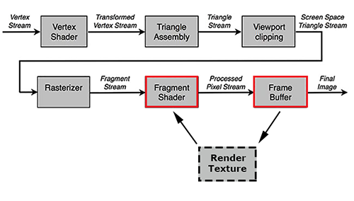
The fact is that it is impossible to access the contents of the frame buffer (frame buffer) in which that “back layer” is located during the execution of the fragment shader (fragment shader) due to the operating logic of the rendering pipeline (rendering pipeline):

The final image (final image) is formed after the execution of the fragment shader; accordingly, we cannot directly receive it during the execution of the Cg program. So you need to look for workarounds.
In fact, the need for data on the final image within the fragment shader arises quite often. The implementation of most post-processing effects, for example, is unthinkable without access to the “final picture”. For such cases, there is a so-called render to texture: the data from the frame buffer is copied into a special texture, from which it is then read the next time the fragment shader is executed:
In Unity, there are several ways to work with render textures. In our case, the most appropriate use of GabPass is a special type of “passage” (pass) that captures the contents of the screen into the texture where the object will be drawn. Just what we need!
Let's create a simple shader for UI-graphics, add GrabPass to it and return from the fragment function the result of color mixing using the Darken algorithm:
To evaluate the result, let's take the same textures that we used in the graphic editor during the demonstration of blending modes:
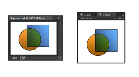
As you can see in the illustration, the results of the rendering of the UI graphics on Unity and the document in Photoshop are identical.
It would be possible to dwell on this if it were not for one “but”: rendering to texture is a rather laborious operation. Even on an average PC, the use of more than 100 such operations simultaneously leads to a noticeable reduction in frame rates. The situation is aggravated by the fact that the speed of GrabPass is inversely related to the display resolution. Imagine what would be the performance in the case of performing a similar procedure on any iPad with ultra-high resolution display? In my case, even a pair of UI objects with “unconventional” mixing in an empty scene led to a drop in FPS below 20.
One optimization suggests itself: why not use a single GrabPass? The original image within the frame remains unchanged, so you can “remove” it once and then use it for all subsequent blending operations.
Unity provides us with a convenient way to realize our plans. It is enough to pass to the GrabPass construction a string with the name of a variable in which we want to store the “common” render texture:
Now, any instance of a material using this shader will receive information from the general render texture and will not perform an expensive GrabPass if it has already been executed by one of the instances. Thus, we get the opportunity to use a large number of mixing operations at a time without serious performance problems.
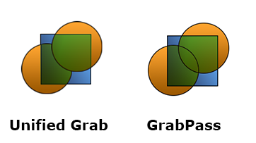
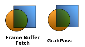
Unfortunately, this solution has one major drawback: since different objects use the same information about the image of the “back layer”, this layer becomes identical for them. That is, such objects "do not see" each other and do not take this information into account when mixing.
The problem becomes apparent if two objects are “superimposed” on each other that use blending:
In addition, even one GrabPass can be too “expensive” for most mobile devices, which means that you need to look for alternative approaches.
Once using GrabPass in any form is too expensive, try to do without it. One of the options: try to change the blend mode, which is performed after the fragment shader (within the Unity rendering pipeline):

This stage is mainly used for processing translucent objects and the possibilities of its modification are severely limited - you will not insert instructions on Cg there. It is possible only with the help of a set of key phrases to configure how the color obtained from the fragment shader should (and should it at all) interact with the color that is “behind” it.
The operation is defined by the following construction:
The logic is that the source color (obtained from the fragment shader) is multiplied by the value returned by the first operand ( SrcFactor ), the target color (the color of the “back” layer) is multiplied by the second operand ( DstFactor ) and the resulting values are added. The list of operands, in turn, is quite limited: you can operate with ones, zeros, source and target colors, as well as the results of their inversion.
The optional BlendOp command, which allows replacing the result of two operands with subtraction, taking the minimum or maximum, expands the possibilities somewhat.
Having shown a little imagination, I was able to implement the following mixing algorithms:
Modify our shader for mixing UI graphics in Darken mode to use BlendOp:
For the demonstration we will use all the same textures:
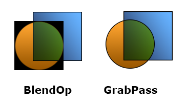
The problem is obvious: due to the fact that we use the blending stage “to fit our needs”, alpha blending is nowhere to go and the transparency of objects is simply ignored. On the other hand, opaque objects are mixed correctly and without loss in performance. So, if it is necessary to use one of the modes, which is possible to recreate using the Blend construction and the object does not have transparent areas, this is probably the best option.
Earlier, I mentioned that it is impossible to access the frame buffer from a fragment shader. In fact this is not true.
In 2013, the EXT_shader_framebuffer_fetch function was added to the OpenGL ES 2.0 specification , which allows access to the frame buffer data from a fragment shader. A few months ago, in the release of Unity 4.6.3, support for this feature from Cg was announced.
We modify our shader to use Framebuffer Fetch:
Perfect. It would seem, what else is needed? No unnecessary operations, maximum performance, you can implement any mixing logic ... Only the illustration above is a fragment of the screenshot taken from the iPad Air. But, for example, in the Unity editor our shader will simply refuse to work.
The problem is that the OpenGL ES specification support is fully implemented only in devices running iOS. On other platforms (even if their graphics subsystem uses the OpenGL ES API), this function may not work, so you cannot count on cross-platform functionality.
We looked at four implementations of blending modes on the Unity game engine:
The only universal and cross-platform solution could not be found, however, the combination of the presented options will allow to use the "mixing" in most cases.
In conclusion, I want to offer a video with a demonstration of some blending modes applied to particle effects, GUI elements, three-dimensional objects and sprites in Unity:
Also, I’m taking a chance (AppEngine - you stand up, I know!) To post a link to the WebGL assembly, where you can experiment online with different blending modes .
Thanks for attention!
And what about the games?
Let's say it became necessary to use Color Dodge mixing for a particle system, or the UI artist made beautiful graphics for the game interface, but some of its elements use some kind of Soft Light. Or maybe you needed to subject a three-dimensional object to a Divide-blending to get the effect straight from Lynch films?
')
In this article we will look at the principle of operation of the popular blending modes and try to recreate their effect as accurately as possible on the Unity game engine.
Mixing algorithms
First, let's figure out what we need to do. Take for example two graphic elements and arrange them so that one overlaps the other:
In the normal (Normal) blending mode, the color of each pixel of the lower layer ( a ) is completely replaced by the pixel color of the layer that “overlaps” it ( b ). Here everything is trivial: most of the graphic objects in games are “mixed” in this way.
In Screen mode, the pixel colors of both layers are inverted, multiplied, and then inverted again. We implement this algorithm in Cg language :
fixed4 Screen (fixed4 a, fixed4 b) { fixed4 r = 1.0 - (1.0 - a) * (1.0 - b); ra = ba; return r; } Note that in the alpha component of the resulting color ( ra ), we transfer the alpha value of the upper layer ( ba ) in order to preserve the ability to independently control the level of transparency of the material.
Overlay algorithm works conditionally: for the "dark" areas the colors are multiplied, and for the "light" ones the analogue of the Screen mode is used.
fixed4 Overlay (fixed4 a, fixed4 b) { fixed4 r = a < .5 ? 2.0 * a * b : 1.0 - 2.0 * (1.0 - a) * (1.0 - b); ra = ba; return r; } 
Blending mode Darken compares the values of each of the three color channels for the two layers and leaves the one that is “darker”.
fixed4 Darken (fixed4 a, fixed4 b) { fixed4 r = min(a, b); ra = ba; return r; } Most of the other modes operate according to similar schemes. If you're interested, the implementation of another 18 mixing algorithms for Cg can be found here: gist.github.com/Elringus/d21c8b0f87616ede9014
So, our task in general form can be formulated as follows: for each pixel of the object's material ( b ), find the pixel that is “under it” ( a ) and, using the selected algorithm, “mix” them.
Implementing with GrabPass
Having received all the necessary mixing algorithms, it may seem that things are small: you only need to get a - the color of the pixels that are located “under” our object. However, this stage turned out to be the most problematic in practical implementation.
The fact is that it is impossible to access the contents of the frame buffer (frame buffer) in which that “back layer” is located during the execution of the fragment shader (fragment shader) due to the operating logic of the rendering pipeline (rendering pipeline):

The final image (final image) is formed after the execution of the fragment shader; accordingly, we cannot directly receive it during the execution of the Cg program. So you need to look for workarounds.
In fact, the need for data on the final image within the fragment shader arises quite often. The implementation of most post-processing effects, for example, is unthinkable without access to the “final picture”. For such cases, there is a so-called render to texture: the data from the frame buffer is copied into a special texture, from which it is then read the next time the fragment shader is executed:

In Unity, there are several ways to work with render textures. In our case, the most appropriate use of GabPass is a special type of “passage” (pass) that captures the contents of the screen into the texture where the object will be drawn. Just what we need!
Let's create a simple shader for UI-graphics, add GrabPass to it and return from the fragment function the result of color mixing using the Darken algorithm:
GrabDarken.shader
Shader "Custom/GrabDarken" { Properties { _MainTex ("Sprite Texture", 2D) = "white" {} _Color ("Tint", Color) = (1,1,1,1) } SubShader { Tags { "Queue" = "Transparent" "RenderType" = "Transparent" } Blend SrcAlpha OneMinusSrcAlpha GrabPass { } Pass { CGPROGRAM #include "UnityCG.cginc" #pragma vertex ComputeVertex #pragma fragment ComputeFragment sampler2D _MainTex; sampler2D _GrabTexture; fixed4 _Color; struct VertexInput { float4 vertex : POSITION; float4 color : COLOR; float2 texcoord : TEXCOORD0; }; struct VertexOutput { float4 vertex : SV_POSITION; fixed4 color : COLOR; half2 texcoord : TEXCOORD0; float4 screenPos : TEXCOORD1; }; VertexOutput ComputeVertex (VertexInput vertexInput) { VertexOutput vertexOutput; vertexOutput.vertex = mul(UNITY_MATRIX_MVP, vertexInput.vertex); vertexOutput.screenPos = vertexOutput.vertex; vertexOutput.texcoord = vertexInput.texcoord; vertexOutput.color = vertexInput.color * _Color; return vertexOutput; } fixed4 Darken (fixed4 a, fixed4 b) { fixed4 r = min(a, b); ra = ba; return r; } fixed4 ComputeFragment (VertexOutput vertexOutput) : SV_Target { half4 color = tex2D(_MainTex, vertexOutput.texcoord) * vertexOutput.color; // , // "" float2 grabTexcoord = vertexOutput.screenPos.xy / vertexOutput.screenPos.w; grabTexcoord.x = (grabTexcoord.x + 1.0) * .5; grabTexcoord.y = (grabTexcoord.y + 1.0) * .5; // , // V . #if UNITY_UV_STARTS_AT_TOP grabTexcoord.y = 1.0 - grabTexcoord.y; #endif fixed4 grabColor = tex2D(_GrabTexture, grabTexcoord); return Darken(grabColor, color); } ENDCG } } Fallback "UI/Default" } To evaluate the result, let's take the same textures that we used in the graphic editor during the demonstration of blending modes:

As you can see in the illustration, the results of the rendering of the UI graphics on Unity and the document in Photoshop are identical.
It would be possible to dwell on this if it were not for one “but”: rendering to texture is a rather laborious operation. Even on an average PC, the use of more than 100 such operations simultaneously leads to a noticeable reduction in frame rates. The situation is aggravated by the fact that the speed of GrabPass is inversely related to the display resolution. Imagine what would be the performance in the case of performing a similar procedure on any iPad with ultra-high resolution display? In my case, even a pair of UI objects with “unconventional” mixing in an empty scene led to a drop in FPS below 20.
Implementing with Unified Grab
One optimization suggests itself: why not use a single GrabPass? The original image within the frame remains unchanged, so you can “remove” it once and then use it for all subsequent blending operations.
Unity provides us with a convenient way to realize our plans. It is enough to pass to the GrabPass construction a string with the name of a variable in which we want to store the “common” render texture:
GrabPass { "_SharedGrabTexture" } Now, any instance of a material using this shader will receive information from the general render texture and will not perform an expensive GrabPass if it has already been executed by one of the instances. Thus, we get the opportunity to use a large number of mixing operations at a time without serious performance problems.
Unfortunately, this solution has one major drawback: since different objects use the same information about the image of the “back layer”, this layer becomes identical for them. That is, such objects "do not see" each other and do not take this information into account when mixing.
The problem becomes apparent if two objects are “superimposed” on each other that use blending:

In addition, even one GrabPass can be too “expensive” for most mobile devices, which means that you need to look for alternative approaches.
Implementing with BlendOp
Once using GrabPass in any form is too expensive, try to do without it. One of the options: try to change the blend mode, which is performed after the fragment shader (within the Unity rendering pipeline):

This stage is mainly used for processing translucent objects and the possibilities of its modification are severely limited - you will not insert instructions on Cg there. It is possible only with the help of a set of key phrases to configure how the color obtained from the fragment shader should (and should it at all) interact with the color that is “behind” it.
The operation is defined by the following construction:
Blend SrcFactor DstFactor The logic is that the source color (obtained from the fragment shader) is multiplied by the value returned by the first operand ( SrcFactor ), the target color (the color of the “back” layer) is multiplied by the second operand ( DstFactor ) and the resulting values are added. The list of operands, in turn, is quite limited: you can operate with ones, zeros, source and target colors, as well as the results of their inversion.
The optional BlendOp command, which allows replacing the result of two operands with subtraction, taking the minimum or maximum, expands the possibilities somewhat.
Having shown a little imagination, I was able to implement the following mixing algorithms:
- Darken:
BlendOp Min Blend One One - Lighten:
BlendOp Max Blend One One - Linear Burn:
BlendOp RevSub Blend One One - Linear Dodge:
Blend One One - Multiply:
Blend DstColor OneMinusSrcAlpha
Modify our shader for mixing UI graphics in Darken mode to use BlendOp:
BlendOpDarken.shader
Shader "Custom/BlendOpDarken" { Properties { _MainTex ("Sprite Texture", 2D) = "white" {} _Color ("Tint", Color) = (1,1,1,1) } SubShader { Tags { "Queue" = "Transparent" "RenderType" = "Transparent" } BlendOp Min Blend One One Pass { CGPROGRAM #include "UnityCG.cginc" #pragma vertex ComputeVertex #pragma fragment ComputeFragment sampler2D _MainTex; fixed4 _Color; struct VertexInput { float4 vertex : POSITION; float4 color : COLOR; float2 texcoord : TEXCOORD0; }; struct VertexOutput { float4 vertex : SV_POSITION; fixed4 color : COLOR; half2 texcoord : TEXCOORD0; }; VertexOutput ComputeVertex (VertexInput vertexInput) { VertexOutput vertexOutput; vertexOutput.vertex = mul(UNITY_MATRIX_MVP, vertexInput.vertex); vertexOutput.texcoord = vertexInput.texcoord; vertexOutput.color = vertexInput.color * _Color; return vertexOutput; } fixed4 ComputeFragment (VertexOutput vertexOutput) : SV_Target { return tex2D(_MainTex, vertexOutput.texcoord) * vertexOutput.color; } ENDCG } } Fallback "UI/Default" } For the demonstration we will use all the same textures:

The problem is obvious: due to the fact that we use the blending stage “to fit our needs”, alpha blending is nowhere to go and the transparency of objects is simply ignored. On the other hand, opaque objects are mixed correctly and without loss in performance. So, if it is necessary to use one of the modes, which is possible to recreate using the Blend construction and the object does not have transparent areas, this is probably the best option.
Implementing with Framebuffer Fetch
Earlier, I mentioned that it is impossible to access the frame buffer from a fragment shader. In fact this is not true.
In 2013, the EXT_shader_framebuffer_fetch function was added to the OpenGL ES 2.0 specification , which allows access to the frame buffer data from a fragment shader. A few months ago, in the release of Unity 4.6.3, support for this feature from Cg was announced.
We modify our shader to use Framebuffer Fetch:
FrameBufferFetchDarken.shader
Shader "Custom/FrameBufferFetchDarken" { Properties { _MainTex ("Sprite Texture", 2D) = "white" {} _Color ("Tint", Color) = (1,1,1,1) } SubShader { Tags { "Queue" = "Transparent" "RenderType" = "Transparent" } Blend SrcAlpha OneMinusSrcAlpha Pass { CGPROGRAM #include "UnityCG.cginc" #pragma vertex ComputeVertex #pragma fragment ComputeFragment sampler2D _MainTex; fixed4 _Color; struct VertexInput { float4 vertex : POSITION; float4 color : COLOR; float2 texcoord : TEXCOORD0; }; struct VertexOutput { float4 vertex : SV_POSITION; fixed4 color : COLOR; half2 texcoord : TEXCOORD0; }; VertexOutput ComputeVertex (VertexInput vertexInput) { VertexOutput vertexOutput; vertexOutput.vertex = mul(UNITY_MATRIX_MVP, vertexInput.vertex); vertexOutput.texcoord = vertexInput.texcoord; vertexOutput.color = vertexInput.color * _Color; return vertexOutput; } fixed4 Darken (fixed4 a, fixed4 b) { fixed4 r = min(a, b); ra = ba; return r; } fixed4 ComputeFragment (VertexOutput vertexOutput #ifdef UNITY_FRAMEBUFFER_FETCH_AVAILABLE , inout fixed4 fetchColor : COLOR0 #endif ) : SV_Target { half4 color = tex2D(_MainTex, vertexOutput.texcoord) * vertexOutput.color; #ifdef UNITY_FRAMEBUFFER_FETCH_AVAILABLE fixed4 grabColor = fetchColor; #else fixed4 grabColor = fixed4(1, 1, 1, 1); #endif return Darken(grabColor, color); } ENDCG } } Fallback "UI/Default" } 
Perfect. It would seem, what else is needed? No unnecessary operations, maximum performance, you can implement any mixing logic ... Only the illustration above is a fragment of the screenshot taken from the iPad Air. But, for example, in the Unity editor our shader will simply refuse to work.
The problem is that the OpenGL ES specification support is fully implemented only in devices running iOS. On other platforms (even if their graphics subsystem uses the OpenGL ES API), this function may not work, so you cannot count on cross-platform functionality.
Conclusion
We looked at four implementations of blending modes on the Unity game engine:
- GrabPass is the most resource-intensive, but reproduces all blending modes as accurately as possible;
- Unified Grab is a GrabPass optimization, seriously gains in performance while simultaneously performing several blending operations, but eliminates the possibility of mixing objects with each other;
- BlendOp works as fast as possible, however, it allows you to implement only a limited number of modes and does not support translucent materials;
- Frame Buffer Fetch works just as quickly, correctly reproduces all modes, but its use is possible only on devices running iOS.
The only universal and cross-platform solution could not be found, however, the combination of the presented options will allow to use the "mixing" in most cases.
In conclusion, I want to offer a video with a demonstration of some blending modes applied to particle effects, GUI elements, three-dimensional objects and sprites in Unity:
Also, I’m taking a chance (AppEngine - you stand up, I know!) To post a link to the WebGL assembly, where you can experiment online with different blending modes .
Thanks for attention!
Source: https://habr.com/ru/post/256439/
All Articles