New graphics mode: CGA in 1024 colors
It's about the " 8088 MPH " demo, which won the Revision 2015 's Oldskool Demo competition. Together with Trixter , reenigne and Scali we did it. And I got the opportunity not only to work with a group of programming wizards, but also to break world records in making demos for the good old IBM PC, mom and dad of the modern x86 platform.
If for some reason you didn’t have an IBM PC XT x86 with a CGA adapter, you can watch the demo on YouTube:
')
Technical details are contained in the post reenigne , and I decided to tell this story in a more visual form.
The trick with the support of a large palette was invented by me some time ago, when I looked at the reenigne code that performed the composite CGI emulation for DOSBox . Having brought to a decent mind the concept of this hack, I told the reenigne about it so that it could look at my solution and test it on real hardware. As a result, we have a recipe:
- take two friends, though undocumented, hack. Mix together to get the desired effect.
- add another hack
- check, correct, repeat
The beginning of the tutorial is written specifically for those who are not very familiar with CGA.
Old trick number 1: 16-color graphics on RGBI
Short course basics CGA: the first graphic standard for the PC. 16 KB memory buffer, works with MC6845 CRTC. Video output: NTSC through the RCA plug, or the DE9 connector, which outputs the RGBI signal (red, green, blue, intensity). The last option is exactly what people represent when they hear about the CGA - digital TTL signal, each component can be turned on or off, a total of 16 colors.
The standard modes supported by the BIOS are high resolution (640x200) in 2 colors and medium (320x200) in 4 colors. Do not turn around: in high resolution, only the fill color can be changed, and the background color is always black. On average, you can change the background color, while the other three are predetermined by fixed palettes .
IBM casually mentioned another mode, in 16 colors and low resolution, which is “not supported in ROM” - and did not provide any information on how to work with it. But this casket opened with a crowbar.
Low resolution mode
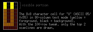
This is not a graphic mode, but a slightly modified text mode of 80 columns. You adjust the CRTC registers and get 100 lines instead of 25. It turns out that the character occupies a rectangle of 8x2 pixels - a quarter of the usual 8x8. Filling the screen with the magical ASCII character 0xDE divides each character into left and right "pixels" that correspond to the background and fill. These two colors can individually assign any of the 16 values of the CGA-mode, as in any text mode of the CGA - the main thing is not to forget to turn off the flicker.

In the picture there is an 8x8 square for the 0xDE symbol (yellow is a fill, black is a background). In the low resolution mode, only two upper rows of pixels (raster lines) are displayed on the screen, and two rectangles of 4x2 pixels are next to each other.
Here you have the mode: 160x100 @ 16c. It has been used since at least 1983 , but has not gained popularity. To make it look tidy, it is necessary to spend precious resources of the CPU, otherwise it is impossible to avoid the “snow” on the screen.
Macrocom method
You ask - since this is a text mode, why not use the entire set of ASCII characters? Really. In the mid-80s, this technique was tested by brave men from Macrocom , who combined a trick of 100 lines with ASCII-art, and received what is called “hellish ANSI”.
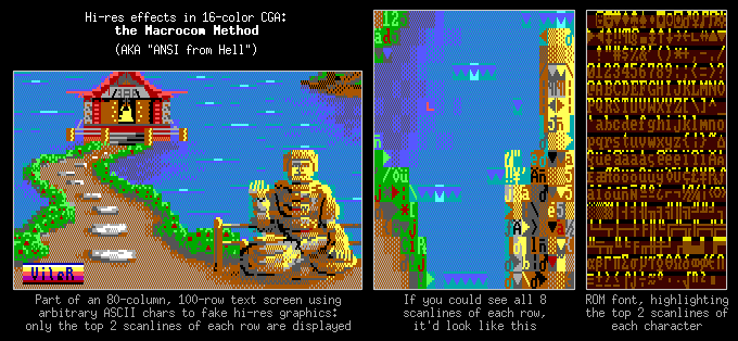
In the picture: a part of the 80x100 text screen that uses random ASCII characters to emulate high resolution graphics. Only the top two rows of raster lines in each character string are displayed.
In the middle - what the screen would look like if you saw the whole characters.
On the right is a ROM font, the top two raster lines of each character are highlighted.
In a sly way using the character set, you can make the viewer think that he sees the 640x200 mode, although each 8x2 character can contain only 2 colors. And to draw in this mode from scratch is an occupation for special gourmets ...
This trick relates to our demo only indirectly: we counted on composite displays. Even if the CGA composite output were not so buggy in the 80 column mode, it would still not be possible to output it to NTSC in such detail.
Old trick number 2: 16 colors through composite output
Digital RGB monitors were rarely seen in the CGA era, but the CGA also provided composite output with a picture that was almost compatible with NTSC. Here we will sacrifice permission, but we will win back with flowers.
Straight colors
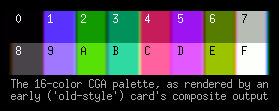
At the composite output, a palette of 16 colors is represented by a series of color signals, in which the hue is determined by the phase relative to the reference signal (the NTSC color burst). The NTSC color frequency (3.579545 MHz) just corresponds to 160 color cycles per active line of the CGA raster.
Colors are directly created by iron as color signals, so we call them “straight colors”. IBM had two versions of CGA that produced composite video in different ways: the new maps contained additional contours that made it possible to bring the palette in the most conformity with RGBI. For the demo, we used old flashcards, since we tested everything on them.
But 16 colors would not be enough for us, would it? They are also ugly to the same. But there is a way to do better.
Parasitic colors
Due to bandwidth limitations, NTSC does not fully separate color and brightness. Any high-resolution detail (whose frequency is greater than the NTSC frequency) is blurred during decoding. Symbols appear at the edges of parasitic colors.
Remember how we got 160 color cycles per active CGA raster line? The CGA standard gives either 320 or 640 active pixels per line. We can turn on and off pixels 2 or 4 times faster than the color rendition frequency. Since these high-frequency details are not completely separated with color information, it turns out that the pixel hue or transition between pixels depends on its position within the period of the color cycle.
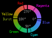
Sometimes the NTSC color cycle is represented as a circle - one full period is equal to a 360 ° rotation, and we have 160 full turns per raster line.
Suppose we have a 640x200 mode, where 4 pixels fit in one digital cycle — by moving one pixel to the left or right, we move the color wheel 90 ° and, accordingly, change the hue by 90 °. In the 320x200 mode, we turn the wheel 180 °. That is, to manipulate the details in high resolution mode means to create colors that are parasitic phenomena imperfect transmission method NTSC.
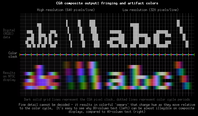
In the picture: the result of the impossibility of full color decoding in the form of color strokes. The text in the mode of 80 columns (left) is almost not readable, unlike the text in 40 columns (right).
To reduce the parasitic effects on the receiving side, different filters are often used. But since this is technology, not magic; complete separation of details and color cannot be done, and other artifacts (such as echoes) are obtained as side effects.
Solid parasitic colors
But all these parasitic colors are just side effects of the non-ideal coding scheme. But, like any disadvantage, it can be turned into an advantage. If you look at these effects, it becomes clear: every periodic composite signal with the same frequency as the color rendition frequency (160 per line) will be decoded as a solid color.
Our 16 straight colors refer to this type of periodic composite signal. But wait - if we play with pixels in high resolution, we can get our own periodic waveforms! Any pattern of dots will fit as long as it repeats at the desired frequency. So we get solid colors that are not included in the straight line palette.

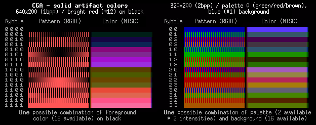
The classic way is to switch to BIOS mode No. 6, 640x200 with 2 colors, white on black, and turn on the color-burst bit. In this resolution, 4 pixels will fit into the color refresh period, and for 1 bit per pixel, 16 patterns will be obtained — that is, 16 colors.
Practically, Steve Wozniak made a color rendition on Apple] [. In general, on the old CGA-card, 16 colors exactly match the 16 colors of the low-resolution mode of Apple. In short, the pixels themselves are white, the color is transmitted only by their mutual arrangement.
But that is not all! CGA, in spite of everything, has an advantage over Apple. Our pixels defining the patterns are not required to be white. In 620x200 mode, we can specify the fill of any of 16 colors (the background is always black). By assigning a different color to the same pixel patterns, we get a palette for it with a new set of colors. Of course, you can only use one set of 16 colors at a time, but at least you can choose which one.
We also have a 320x200 mode with a palette of 4 straight colors. And only one of them, №0 (background), can be changed freely. For the rest, you can change the intensity, but we can only get green / red / yellow or cyan / magenta / white. To get the undocumented palette blue / red / white, you need to turn off the digital synchronization bit, which is why the composite image will be black and white.
Since pixels are twice as thick in this mode, you can only squeeze them into the color update cycle - but for 2 bits per pixel, the total number of parasitic colors will still be 16. Possible combinations of palettes and a selectable background color give us several sets of 16 - color palettes.
Here something needs to be clarified. Since we have 160 color cycles per line, many believe that the CGA graphics modes available on the composite signal are 160x200 modes - but this is not quite so. The effective color resolution is, in fact, 160x200, and it is impossible to get a smaller resolution using parasitic colors. But, as we have seen, in NTSC, the grid of pixels and the grid of colors are not the same. Therefore, the horizontal resolution is an open question, it depends on the sampling and filtering of the signal, and varies depending on what forms of the color signal you use.
IBM has not documented these artifact tricks, but the concept has been used even in the oldest games - for example, Microsoft Decathlon and Flight Simulator from 1982. And the limit of 16 colors always remained.
However, if you are still reading the text, you can guess that this limitation can be overcome, and you can even guess how.
256 colors
Our selection of 16 parasitic colors depends on the palette and color register settings. So, it is necessary to change the registers of specific raster rows and get more than 16 colors on the screen. Is not it?
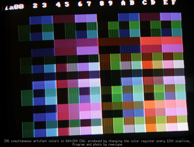
At CGA, this has already been done, and this technique can be brought to 256 colors - but we did not use this approach in the demo. I stumbled upon our technique by pure chance, driven by curiosity.
Recall how a pattern of colors and dots of the desired length (four pixels at 640x200 or two at 320x200) gives a solid color to the composite display. When I tested the composite emulation on DOSBox, I remembered that. And at the same time, I experimented with the hellish ANSI graphical hack.
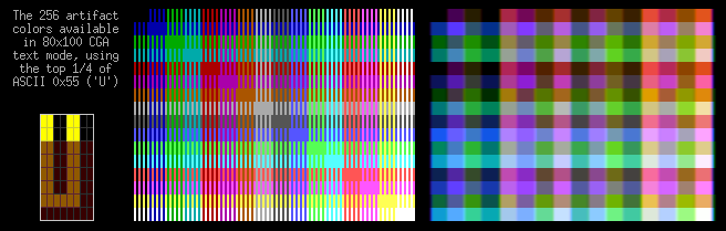
Let's return to one of the parts of the ROM font in the mode of 80 columns, which has 2 upper raster lines highlighted:
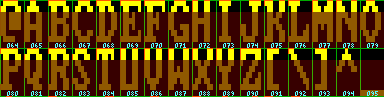
Look, for example, at this symbol:
In 80x100 mode, only the two upper raster lines are displayed. See those 25% symbol images? Two fill color dots and two background points horizontally duplicated. We are in high resolution mode and 80 columns are displayed, so for each character there are two color cycles - which correspond to these two similar halves. And the two upper raster lines are identical.
It is this repeating pattern that gives us a solid spurious color in NTSC. This is the same waveform that is available in 320x200 mode. Only now it is available in text mode, where we can freely assign and fill color, and background color, their available 16 colors.
That is, we already have 256 options - i.e. the ability to display more than 16 colors in CGA without blinking, blurring and other effects.
Possible combinations:
512 flowers
But that is not all! Moving in this direction, I began to study the font from ROM in search of other useful templates. Some symbols give us the same waveforms as U — H, V, Y, and ¥. But only one with another suitable sequence of bits exactly where necessary - 0x13, or.
The upper two lines of the raster U give the bit mask 11001100 for the fill and the background. '' gives 01100110 - shift to the right, or a phase shift of 90 °. This complements U and creates a nice full palette, because we get all the colors that the waveform "... 1100 ..." can offer: moving from 'U' to ', we shift the phase by 90 ° (0110); 180 ° and 270 ° are obtained when we swap the fill and background colors of 'U' and '' respectively - the same as for '0011' and '1001'.

And we got even more - 512 flowers! Of course, there are actually fewer of them, there are doubles and very little different shades. But it seems to be the limit - there are no other suitable characters in the font. There is an alternative 8x8 “thin” font in CGA, but firstly, there is a need to poke around in the card, and secondly, there are no useful bit patterns.
With pride in sharing my technique of increasing the number of colors by 32 times with reenigne, I did not expect that he would have a truly devilish plan to double the available number of colors ...
1024 colors
And then comes the black magic, all the laurels of which should be attributed to reenigne
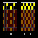
Pay attention to these two symbols, which have an interesting first raster line. Unfortunately, the second line is different from the first, and this will spoil our solid color effect. These are ASCII codes 0xB0 and 0xB1. It would be great to be able to cut off the second, inappropriate line of the raster ... And there is such an opportunity.
Details can be read in the post reenigne, but in short, the idea is as follows: starting each new CRTC frame with the start of a new raster line and playing with the starting address, it is possible to arrange our characters so that the first raster line of each character is repeated twice.
And now we can use these two symbols, which give us two more palettes of 256 colors:
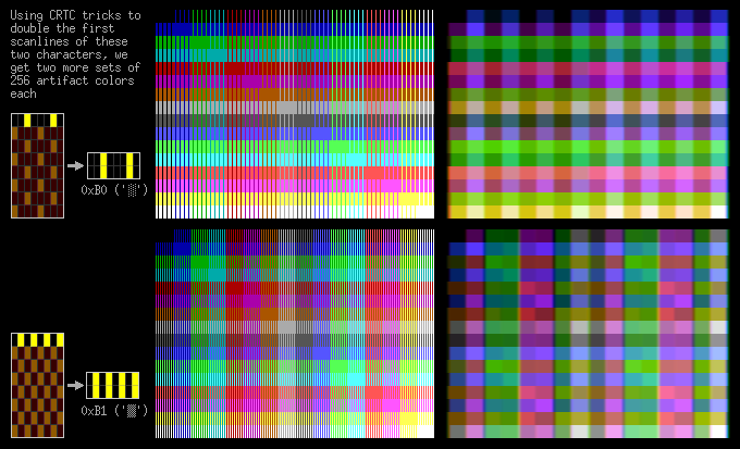
Of course, such a fuss gives a big load to the unfortunate 4.77MHz 8088 percent, so besides static pictures there is little that can be done. The variant with 512 colors and using ASCII 0x55 and 0x13 is much faster - installed, and forgot.
There is another problem with composite displays - a hardware bug that leads to incorrect vertical synchronization and skipping of color sync. There are ways of compensation - but there is no 100% reliable for any monitor. It took a lot of time for testing and calibration.
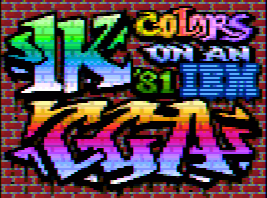
Well, in the end we got 1K colors for the 1981 IBM CGA in the effective resolution of 80x100 “puffy pixels”. Plump they are in memory and visually. Of course, 80x100 is too small a field for drawing. But restrictions are part of an interesting task that is always present in demos. Keep your monitors with a resolution of 4K - 0.008 megapixels should be enough for everyone!
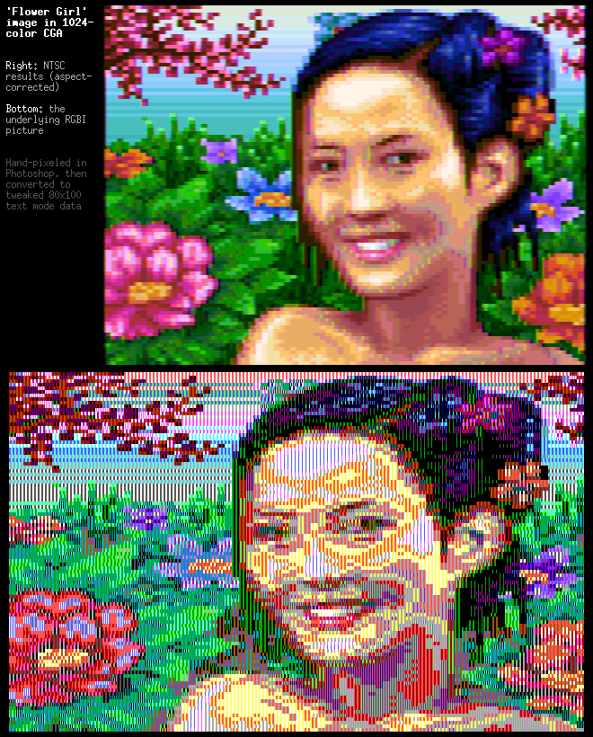
In the picture: above - the result on a calibrated NTSC-display. Below is an option with output to RGBI. Drawn in Photoshop manually and converted to 80x100 format.
Source: https://habr.com/ru/post/256409/
All Articles